1
-J05004
REV. 2013-06-27
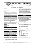
LED HEADLAMP KIT
GENERAL
Kit Number
73390-10A, 67700040A, 67700173
Models
To prevent accidental vehicle start-up, which could cause
death or serious injury, remove main fuse before proceeding. (00251b)
For model fitment information, see the P&A Retail Catalog or
the Parts and Accessories section of www.harley-davidson.com
(English only).
1.
Follow the instructions in the service manual to disconnect
the battery cables, negative (1) cable first or remove the
main fuse.
Additional Parts Required
2.
See the service manual and follow the instructions to
replace the headlamp, removing any trim rings and hardware. Save the hardware and trim ring for installation. On
black version, use the included black retainer ring.
The rider's safety depends upon the correct installation
of this kit. Use the appropriate service manual procedures.
If the procedure is not within your capabilities or you do
not have the correct tools, have a Harley-Davidson dealer
perform the installation. Improper installation of this kit
could result in death or serious injury. (00333a)
3.
Disconnect the harness and remove the headlamp:
NOTE
4.
This instruction sheet references service manual information.
A service manual for your model motorcycle is required for this
installation and is available from a Harley-Davidson dealer.
a.
2006-2010 FLHTCUSE Models: Unplug cigar lighter
and garage door opener to remove existing jumper
harness.
b.
All other Models: Remove existing jumper harness.
Remove the mounting ring and mounting ring hardware.
Discard the mounting ring and headlamp.
INSTALLATION
Separate purchase and installation of additional parts or
accessories may be required for proper installation of this kit
on your model motorcycle. See the P&A Retail Catalog or the
Parts and Accessories section of www.harley-davidson.com
(English only) for a list of required parts or accessories for your
model.
Connect positive (+) battery cable first. If positive (+) cable
should contact ground with negative (-) cable connected,
the resulting sparks can cause a battery explosion, which
could result in death or serious injury. (00068a)
Kit Contents
1.
2014 and later Touring Models: See the P&A Retail
Catalog or the Parts and Accessories section of
www.harley-davidson.com (English only) for a list of
required parts or accessories for your model.
2.
See the service manual and install the new mounting ring.
3.
Connect the harness to headlamp:
See Figure 5 and Table 1.
REMOVAL
To prevent accidental vehicle start-up, which could cause
death or serious injury, disconnect battery cables (negative
(-) cable first) before proceeding. (00307a)
Disconnect negative (-) battery cable first. If positive (+)
cable should contact ground with negative (-) cable connected, the resulting sparks can cause a battery explosion,
which could result in death or serious injury. (00049a)
-J05004
4.
a.
Domestic Models: See Figure 5. The position lamp
connector (6) is not used.
b.
HDI Models: Connect the position lamp connector to
the harness connector.
c.
2006-2010 FLHTCUSE Models: Use harness jumper
71628-04 to reconnect the cigar lighter, garage door
opener and headlamp.
See the service manual and follow the instructions to install
the headlamp.
Many Harley-Davidson® Parts & Accessories are made of plastics and metals which can be recycled.
Please dispose of materials responsibly.
1 of 3
is06580
After installing seat, pull upward on seat to be sure it is
locked in position. While riding, a loose seat can shift
causing loss of control, which could result in death or
serious injury. (00070b)
5.
5
2
Install seat (if removed) according to the instructions in
the service manual.
HEADLAMP ALIGNMENT PROCEDURE
4
1
3
is06581a
1.
2.
3.
4.
5.
2
3
Perpendicular line
Vertical line
25 feet (7.6 meters)
Low beam lens centerline
Horizontal line - align top of left side of low beam
(for vertical alignment)
Figure 2. Checking Headlamp Alignment
Alignment of High Beam (Left-to-Right Alignment)
1
1. Projector beam optic (typical)
2. Reflector optic (typical)
3. Centerline of low beam
Figure 1. Headlamp Configuration
1.
Verify that the headlamp lens is perpendicular to the front
forks for proper left-to-right alignment.
2.
See Figure 3. With vehicle laden and upright, point the
front wheel straight forward at wall.
3.
Turn on the high beam and align the center of the high
beam hot spot with the intersection of the horizontal and
vertical lines (3).
NOTE
Because of the differences between an LED headlamp and a
halogen headlamp, the alignment procedure is performed on
both the low beam and the high beam. Read these instructions
thoroughly to properly align the LED headlamp.
1.
Verify that front and rear tire inflation pressures are correct
and that the suspension is adjusted to the weight of the
principal rider. Refer to the owner's manual.
2.
Fill fuel tank or add an equal amount of ballast.
3.
See Figure 2. Position motorcycle so that front axle is 25
feet (7.6 meters) (3) from wall.
is06616
1
2
3
NOTE
As the weight of the rider will compress the suspension slightly,
have a person whose weight is approximately the same as that
of the principle rider sit on the motorcycle.
4.
See Figure 1. With vehicle laden and upright, point the
front wheel straight forward at wall and measure the distance from the floor to the center of the low beam lens
(3). Record this measurement.
5.
See Figure 2. Draw a horizontal line on the wall at (5) on
the wall that is the same measurement as the measurement recorded in Step 4.
6.
7.
1. Outline of high beam light pattern
2. Horizontal line
3. Intersection of horizontal and vertical lines
Draw a vertical line (2) off of the perpendicular line (1) so
that it crosses through the horizontal line drawn in the
previous step.
If equipped with additional lighting such as passing lamps,
verify those lights are OFF during the alignment procedure.
-J05004
Figure 3. Alignment of Headlamp High Beam
Alignment of Low Beam (Vertical Alignment)
1.
See Figure 4. Align the left side of the horizontal line of
the low beam light pattern (3) with horizontal line (2) drawn
on the wall. If necessary, adjust the headlamp position by
following the adjustment procedure in the service manual.
2 of 3
is06613a
1
SERVICE PARTS
5
is06623b
1
4
3
5
4
2
5
3
6
1
2
1.
2.
3.
4.
5.
Outline of low beam light pattern
Horizontal line
Left side of low beam light pattern
Vertical line
Projector beam optic only
Figure 4. Alignment of Headlamp Low Beam
-J05004
Figure 5. Service Parts: LED Headlamp Kit
Table 1. Service Parts: LED Headlamp Kit
Item
Description (Quantity)
Part Number
1
LED headlamp (chrome) (includes 73391-10A
Item 4)
1
LED headlamp (black) (includes
Item 4)
2
LED headlamp (chrome) (includes 67700188
Item 4)
3
Retainer ring (black)
Not Sold Separately
4
Washer (8) (FLHR only)
6717
5
Mounting ring assembly
68124-04B
6
Position lamp connector (HDI)
9897
67700042A
3 of 3