1
-J05515
REV. 2011-12-02
HEADLAMP MODULATION KIT, FLD/FLH/FLT MODELS
GENERAL
Table 1. Kit Contents
Kit Number
Description (Quantity)
67700139
Models
Part Number
Modulator assembly
Not sold separately
Mounting tape
Not sold separately
For model fitment information, see the P&A retail catalog or
the Parts and Accessories section of www.harley-davidson.com
(English only).
Cable straps (3)
10065
For use with a 1 watt - 60 watt bulb load at 12VDC.
PREPARATION
This kit is not compatible with LED headlamps.
NOTE
Installation Requirements
For vehicles equipped with security siren:
Electrical Contact Lube (H-D Part No. 99861-02) or equivalent
is required after battery cable disconnection. This item is
available from a Harley-Davidson dealer.
•
2007 and later: Verify that the Hands-Free Fob is present.
Turn the ignition key switch to IGNITION.
•
2006 and earlier: Disarm the siren with the key fob.
For Vehicles With Main Fuse:
The rider's safety depends upon the correct installation
of this kit. Use the appropriate service manual procedures.
If the procedure is not within your capabilities or you do
not have the correct tools, have a Harley-Davidson dealer
perform the installation. Improper installation of this kit
could result in death or serious injury. (00333a)
To prevent accidental vehicle start-up, which could cause
death or serious injury, remove main fuse before proceeding. (00251b)
1.
NOTE
This instruction sheet refers to service manual information. A
service manual for this year/model motorcycle is required for
this installation and is available from a Harley-Davidson dealer.
Kit Contents
is07150
See the service manual and remove the main fuse.
For Vehicles With Main Circuit Breaker:
To prevent accidental vehicle start-up, which could cause
death or serious injury, disconnect negative (-) battery
cable before proceeding. (00048a)
1.
See the service manual to remove the seat and disconnect
the negative (black) battery cable from the negative (-)
battery terminal. Retain all seat mounting hardware.
2.
For ALL models: Turn the ignition key switch OFF if not
already done.
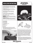
Figure 1. FLD/FLH/FLT Headlamp Modulation Kit
-J05515
Many Harley-Davidson® Parts & Accessories are made of plastics and metals which can be recycled.
Please dispose of materials responsibly.
1 of 3
Position the modulator switch/sensor assembly to the
clamp, and align the holes. Fasten the switch to the
bracket with the screw, and tighten to 72-108 in-lbs (8.012.0 Nm)
INSTALLATION
NOTE
The switch/sensor wiring must be mounted to the handlebar
externally.
FLD (Dyna ® Switchback) and FLHR models: See the service manual to disconnect and remove the headlamp from the
nacelle.
FLHT and FLTR models: See the service manual to remove
the outer fairing and windshield.
FLD Models
1.
Remove the clutch hand lever bracket upper clamp screw.
2.
Get the modulator assembly from the kit. Position the
modulator switch/sensor assembly to the clamp, and align
the holes.
3.
Fasten the switch to the bracket with the screw, and tighten
to 72-108 in-lbs (8.0-12.0 Nm)
4.
5.
Route the modulator wire conduit down the handlebar and
into the rear opening of the nacelle. Plug the modulator
input pin connector into headlamp connector [38B] on the
vehicle harness inside the nacelle.
Fasten the wire conduit to the handlebar with cable straps
from the kit.
3.
NOTE
The module should be mounted to the underside of the clutchlever side fairing support bracket.
4.
Clean the module mounting area on the fairing support
bracket with a 50-50 mixture of isopropyl alcohol and distilled water. Allow to dry thoroughly.
5.
Remove the liner from the adhesive tape on the module.
Carefully position the module to the fairing support bracket,
and press firmly into place. Hold the module in position
with steady pressure for a few seconds.
6.
Plug the modulator input pin connector into headlamp
connector [38B] on the vehicle harness.
7.
Retain the wires inside the fairing with cable straps from
the kit.
FLTR Models
NOTES
•
Ambient temperature should be at least 60 °F (16 °C) for
proper adhesion of the modulator to the vehicle.
Get the modulator assembly from the kit.
•
From inside the nacelle, feed the modulator switch/sensor
and wires through the clutch-lever side opening below the
handlebar.
Allow AT LEAST 24 hours after applying the modulator
before exposing to extreme weather.
•
The adhesive bond will increase to maximum strength
after about 72 hours at normal room temperature.
Remove the clutch hand lever bracket upper clamp screw.
1.
Get the modulator assembly from the kit.
FLHR Models
1.
2.
Position the modulator switch/sensor assembly to the
clamp, and align the holes. Fasten the switch to the
bracket with the screw, and tighten to 72-108 in-lbs (8.012.0 Nm)
3.
Fasten the wire conduit to the handlebar with cable straps
from the kit.
4.
Plug the modulator input pin connector into the headlamp
connector [38B] on the vehicle harness inside the nacelle.
5.
Secure the module and wires inside the nacelle with a
cable strap from the kit.
From inside the fairing, feed the modulator switch/sensor
and wires through the center of the radio carrier bracket
and upward to the clutch-lever side handlebar controls.
2.
NOTES
•
Ambient temperature should be at least 60 °F (16 °C) for
proper adhesion of the modulator to the vehicle.
•
Allow AT LEAST 24 hours after applying the modulator
before exposing to extreme weather.
•
The adhesive bond will increase to maximum strength
after about 72 hours at normal room temperature.
1.
Get the modulator assembly from the kit. Move the clutchlever side rubber handlebar grommet aside.
From inside the fairing, feed the modulator switch/sensor
and wires through the opening between the inner fairing
and fairing cap.
Remove the clutch hand lever bracket upper clamp screw.
-J05515
Remove the clutch hand lever bracket upper clamp screw.
Position the modulator switch/sensor assembly to the
clamp, and align the holes. Fasten the switch to the
bracket with the screw, and tighten to 72-108 in-lbs (8.012.0 Nm)
3.
FLHT Models
2.
Fasten the wire conduit to the handlebar with a cable strap
from the kit.
Fasten the wire conduit to the handlebar with a cable strap
from the kit. Fasten the conduit to one of the harnesses
above the steering head with a second cable strap.
NOTE
The module should be mounted to the brake-lever side wall of
the radio carrier bracket.
4.
Clean the module mounting area on the radio carrier
bracket with a 50-50 mixture of isopropyl alcohol and distilled water. Allow to dry thoroughly.
5.
Remove the liner from the adhesive tape on the module.
Carefully position the module to the radio carrier bracket,
and press firmly into place. Hold the module in position
with steady pressure for a few seconds.
NOTE
The modulator will support only one headlamp bulb. For highest
visibility to oncoming traffic, apply modulation to the LEFTSIDE headlamp.
2 of 3
6.
Plug the modulator input pin connector into left-side
headlamp connector [38B] on the vehicle harness.
7.
Retain the wires inside the fairing with a cable strap from
the kit.
8.
Plug the modulator output pin connector into the back of
the left-side headlamp.
and a substantially lower level, approximately four times
per second. The headlamp will not go completely dark
during the modulation cycle.
The high beam headlamp does not modulate.
3.
FLD and FLHR models: See the service manual to install
the headlamp into the nacelle.
FLHT and FLTR models: See the service manual to install
the outer fairing and windshield.
ALL Models Except FLT
Plug the modulator output pin connector into the back of the
headlamp.
RETURN TO SERVICE
NOTE
Verify that the ignition key switch is in the OFF position before
installing the main fuse or attaching the negative battery cable.
1.
Models with main fuse: See the service manual and
install the main fuse.
Models with main circuit breaker: See the service
manual and attach the negative battery cable. Apply a
light coat of Harley-Davidson electrical contact lubricant
(Part No. 99861-02), petroleum jelly or corrosion retardant
material to the negative battery terminal.
NOTE
The modulator switch light sensor requires daylight or very
bright indoor lighting to enable headlamp modulation. Aiming
a flashlight directly into the sensor may also provide sufficient
illumination to allow modulation.
2.
Test the headlamp modulation system for proper operation.
Turn the ignition key switch ON. Proper operation is:
•
With the modulation toggle OFF, the headlamp will be
illuminated as normal.
•
With the modulation toggle ON and daylight sensed, the
low beam headlamp will pulsate between full brightness
-J05515
After installing seat, pull upward on seat to be sure it is
locked in position. While riding, a loose seat can shift
causing loss of control, which could result in death or
serious injury. (00070b)
4.
For ALL models: See the service manual and install the
seat.
IN USE
A light sensor mounted in the modulator switch assembly
senses the presence of daylight. Government regulations only
allow headlamp modulation in daylight.
The switch can be used to turn the modulation on or off at any
time, provided it is enabled by the daylight sensor and the low
beam is selected. The high beam headlamp does not modulate.
If equipped, the transmitter in the Remote Control Garage Door
Opener Kit (Part No. 91558-01A) will not work while the low
beam is modulating, Turn the modulator off to operate the
garage door opener.
3 of 3