1
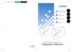
II Bagger/III Bagger Adjustable FLH/FLT
Arms
Installation Instructions
Thank you for a choosing a Supreme Legends USA product.
Supreme Legends Adjustable Extended Bagger Arms are designed to give your FLH/FLT more foot room on
your floorboards, while offering adjustable positions on both the brake and shift sides. The lower & extended
brake arms offer easier braking, with less pressure required for actuation. We hope that you will be pleased with
your purchase. Should you have any questions, please contact our customer service department at (714) 504-0715 or visit us
on the web at www.supremelegendsusa.com.
IMPORTANT WARNING!
IT IS CRITICAL THAT ALL SUPREME LEGENDS USA PRODUCTS AND ACCESSORIES BE PROPERLY AND SECURELY
ATTACHED TO YOUR VEHICLE. IMPROPER ATTACHMENT COULD RESULT IN A MOTORCYCLE ACCIDENT, AND
COULD CAUSE SERIOUS BODILY INJURY OR DEATH TO YOU OR OTHERS. YOU ARE RESPONSIBLE FOR SECURING
THE PRODUCTS AND/OR ACCESSORIES TO YOUR MOTORCYCLE, CHECKING THE PRODUCTS AND/OR
ACCESSORIES PRIOR TO USE AND PERIODICALLY INSPECTING THE PRODUCTS AND/OR ACCESSORIES FOR
ADJUSTMENT, WEAR AND DAMAGE. THEREFORE, YOU MUST READ AND UNDERSTAND ALL OF THE
INSTRUCTIONS, NOTES AND WARNINGS SUPPLIED WITH YOUR SUPREME LEGENDS USA PRODUCTS AND/OR
ACCESSORIES PRIOR TO INSTALLATION OR USE. IF YOU DO NOT UNDERSTAND ALL OF THE INSTRUCTIONS,
NOTES AND WARNINGS, OR IF YOU HAVE NO MECHANICAL EXPERIENCE AND ARE NOT THOROUGHLY
FAMILIAR WITH THE INSTALLATION PROCEDURES, YOU SHOULD HAVE THE PRODUCT AND/OR ACCESSORIES
INSTALLED BY A PROFESSIONAL MECHANIC.
SUPREME LIMITED WARRANTY
Supreme Legends USA offers a limited 18 month, non-transferrable warranty from the date of purchase, to the original
purchaser, on all parts included with this kit to be free of manufacturing defects in materials and workmanship,
excluding normal wear and tear. If the condition of an item requires warranty service, please contact Supreme Legends
USA immediately.
The limited warranty is applicable only if the instructions are followed and the products are used properly. Supreme
Legends USA will determine if it is necessary to return an item for evaluation and validity of warranty claim. If an
article is found to be defective upon inspection by Supreme Legends USA, we will repair or replace the defective
article at our discretion without charge. The customer will pay freight to Supreme Legends USA and we will pay any
applicable return freight. A Return Merchandise Authorization (RMA) form, provided by a customer service
representative, must be included will all returned product, along with a copy of the original receipt. All items must be
packaged in such a fashion as to eliminate any further damage. Unauthorized returns will not be accepted.
SUPREME LIMITED WARRANTY (continued)
Normal wear and tear of Supreme Legends USA products or damage resulting from misuse, accidents, improper
installation, alterations or abuse (including tampering or damage in transit) are not covered by this Limited Warranty.
The purchaser acknowledges that Supreme Legends USA has no control over the attachment of its products to
motorcycles and/or motor vehicles or the attachment of items to Supreme Legends USA products. Accordingly, Supreme
Legends USA cannot assume responsibility for any damage to property arising out of improper attachment or use of its
products. In addition, this Limited Warranty applies only to Supreme Legends USA products and not to other products
used in conjunction with Supreme Legends USA products. This Limited Warranty is in lieu of all other warranties, expressed
or implied, and does not cover consequential damages of any kind that may arise from the use or misuse of any Supreme
Legends USA product.
FOREVER SUPREME
We know how hard people try to keep their motorcycles looking new, but all parts will wear over time. We developed this
program to show our customers that we care. And if you were our customer once you are entitled to be our customer for
life. If you have an old registered Supreme Legends USA part you can trade it in and receive the following discounts on a
new part of equal or lesser value.
Second Year-15% off
Third Year & Beyond- 10% off
DISCLAIMER
THE INSTALLATION OF SUPREME LEGENDS USA PRODUCTS MAY ADVERSERLY AFFECT OR VOID YOUR
MOTORCYCLES FACTORY WARRANTY. WE ARE NOT RESPONSIBLE FOR ANY ISSUES RELATED TO YOUR
MOTORCYCLES FACTORY WARRANTY. OUR PRODUCTS ARE DESIGNED TO BE INSTALLED AT THE SOLE
DISCRETION OF THE MOTORCYCLES OWNER. SUPREME LEGENDS USA HOLDS NO RESPONSIBILITY FOR
MODIFICATIONS TO YOUR MOTORCYCLE AND/OR ITS PERFORMANCE OR WARRANTY DUE TO THE
INSTALLATION OF OUR PRODUCTS.
YOU UNDERSTAND AND AGREE THAT WE MAKE NO REPRESENTATIONS OR WARRANTIES OF ANY KIND,
EXPRESSED OR IMPLIED AS TO ANY MATTER WHATSOEVER, INCLUDING THE CONDITION OF THE PRODUCT OR
ANY COMPONENT PARTS THEREOF, ITS MERCHANTABILITY OR ITS FITNESS FOR ANY PARTICULAR PURPOSE.
EXCEPT AS OTHERWISE PROVIDED HEREIN, WE SHALL NOT BE LIABLE FOR DAMAGES, INCLUDING SPECIAL,
INCIDENTAL OR CONSEQUENTIAL DAMAGES WHETHER IN CONTACT OR IN TORT ARISING OUT OF OR IN
CONNECTION WITH THE PERFROMANCE OF ANY PRODUCT OR ANY COMPONENT PART THEREOF IN ITS USE BY
YOU, AND SHALL NOT BE LIABLE FOR ANY SPECIAL, INCIDENTAL OR CONSEQUENTIAL DAMAGES ARISING OUT
OF OR IN CONNECTION WITH YOUR USE OF THE PRODUCT.
INDEMNITY & RELEASE
a.
You understand and agree that many factors beyond our control affect the operational safety of the
product including, but not limited to the installation of the product according to the instructions
provided with the product;
b.
You also understand and agree that the installation of the product may involve the use of tools,
equipment and construction methods which may present safety hazards which are beyond our control.
c.
Except as otherwise proved herein, you will protect, indemnify, save harmless and release us, our
authorized agents, employees, officers, directors and shareholders from and against all liabilities,
obligations, claims, damages, penalties, causes of action, costs and expenses, imposed upon or
incurred by or asserted against us and our authorized agents, employees, officers, directors and
shareholders or any of our assignees, by you or any third party by reason of any assembly, use,
maintenance, possession or operation of the product, any loss, damage or destruction of the product
as of and after delivery and any other act or event relating to or caused by the product, including but
not limited to, consequential or special damages or any kind, or any failure on your part to perform or
comply with any of the terms and conditions hereof, or any and all liability for property loss or damage,
or any and all damages resulting from death or personal injuries, including loss of services, which any
person may sustain on account of, arising out of, or in connection with any use, maintenance,
possession or operation of the product. In the event that any action, suit or proceeding is brought
against us or any of our authorized agents, employees, officers, directors or shareholders by reason of
any such occurrence, you will, upon request and at your expense, resist and defend such action, suit or
proceeding or cause the same to be resisted and defended by counsel designated and approved by
us.
2
INSTALLATION KIT INCLUDES:
1.
2.
3.
4.
5.
6.
7.
2
(1) .025 thick “wavy” spring washer
(1) Serrated Belleville washer
(1) 1/2” ID .005 thick shim
(2) 5/8” ID Buna O-rings
(1) Stainless Brake Arm Cap Nut
(1) 1” OD x .06 thick shim
(1) 5/8” ID x .02 thick shim
3
1
5
4
*All parts shown in hardware kit will be used in
installation process. Other hardware included with
kit will be installed onto components during
assembly at Supreme Legends USA.
6
7
INSTALLATION
Important Installation Notes:
♦
Please read entire instruction booklet prior to installation. This will familiarize you with the tools required to
install this product and how the included items fit and operate
♦
Before attempting installation of this kit, make sure to check package to be sure you have received all
the necessary items included with this product and that the kit is the correct unit for your motorcycle
♦
We recommend that you obtain your bike’s factory service manual for detailed instructions on the removal of stock parts necessary for the installation of this kit
Preparation
Position motorcycle on a quality motorcycle lift with a weight rating greater than the weight of your motorcycle. Make sure motorcycle is securely positioned and locked down before attempting any work. Raise motorcycle to a comfortable position for installation procedure.
You understand and agree that the product is designed to be installed and used as described in the assembly instructions. You agree not to make any modifications to the product and agree not to use any parts,
components, or accessories in connection with the installation and the use of the product that are not
authorized and approved by us.
3
Installation Steps
Installing the Shift Arm(s)
***PLEASE NOTE-These instructions are for both the II & III
Bagger Series and will vary only slightly.
Step 1: Remove your existing control components, including
any arms, and any end caps or spacers. Remove rear shift
linkage from shift rod. There is no need to adjust the shift rod
from it’s existing position as all adjustments can be made on
the outside arms during the last steps of installation.
Step 2
Step 2: Once all existing components are removed from the
shift shaft, place the 5/8 ID shim at the back side of the shift
shaft. We recommend putting a light coat of silicone grease
on the shim face once it is in place. (If installing a III Bagger
series, you will replace your stock shift shaft with the new one
prior to doing this).
Step 3: Remove bolt completely from rear new rear shift
linkage. Slide over splines and completely against the shim.
Using thread locker (blue is acceptable), replace bolt into
hole, line up into shaft’s retaining groove, and thread down
into bottom half. Tighten securely. There is no need to overtorque this bolt.
Step 3
Step 4: Reconnect shift rod to rear shift linkage, being sure to
use thread locker if necessary.
Step 5: Once step 4 is complete, place the wavy spring
washer into the shift spacer recess (shown below), and place
that end onto the outboard side of the shift shaft, pushing it up
to the primary casing. This washer is meant to retain the
spacer in place while still allowing free movement of shift arms.
On the outboard side of the installed spacer, place the 1/2” ID
shim. We recommending greasing this shim and the face of
the spacer with a light silicone grease for easy shifting.
Step 6: Remove bolt from bottom of shift arm(s) and apply
thread locker to threads. Reinstall bolt, but do not tighten yet.
Place shift arm into approximate desired position on splined
shaft. Being sure to hold the rear shift link at the same time,
squeeze the arms towards each other, and tighten the bolt on
the shift arm snugly. If you are installing a II Bagger control, this
shifter will be used for all shifting, and should be adjusted to
enable comfortable up and down shifting. If you are installing
a III Bagger series, adjust each arm for heel and toe shifting as
necessary, before tightening
anything down. On heel/toe
shifters, the toe shifter will sit
slightly in front of the board,
while the heel shift will sit just
above the rear of your board
to ensure consistent shifting.
Once all adjustments are
made, tighten completely.
Shift Spacer with spring washer
4
Step 4
Step 6
Installing the Brake Arm
Step 1: Begin by removing your brake side floorboard. This will
allow easy access to parts during removal and installation.
Step 2: Remove the nut from your stock brake arm. Remove
any shims and o-rings as well.
Step 3: Locate the pin which holds your existing brake arm to
the master cylinder plunger. You will need to remove the cotter
pin which retains it from the backside. This may take a moment
or two. If you have additional cotter pins, it is sometimes easier
to simply snip the bottom legs of the pin and remove the head,
rather than fight a losing battle with a stubborn pin. Once the
cotter pin is out, remove the main pin, and then the brake arm
(the plunger will move enough to allow you to push it up out of
the way).
Remove any remaining o-rings from the brake shaft. You may
leave any shims on which may be at the back of the shaft as
they should not affect final fitment.
Step 4: Before installing the brake arm, you will need to select
your desired position of adjustment.
To select your mounting position, you will loosen the two bolts
within the slots to allow the brake link to rotate to your position.
Please note, these two bolts, and your positioning bolt, have a
serrated Belleville washer installed to insure non-slippage in their
final position. We still recommend also applying a thread locker
to the bolts before final installation.
Step 3
Pos. 1
Please take note: Brake arms are located at position 2 when
shipped from Supreme. They are NOT tightened, but are left
snug so that you may make any final adjustments.
Due to the contours and extension of these arms, position 1
may only be used on modified exhausts and will likely not fit
with your stock exhaust. We recommend beginning at position
2, which is approximately 10 degrees down from the stock
position, and likely most comfortable for most riders.
Position 3 is 20 degrees down from stock and recommended for
riders with longer inseams.
Pos. 2
Positioning your arm: Place your positioning bolt into the
appropriate location as needed. This bolt will only fully install
into one position, and will match up to it’s hole only when
rotated properly. Once your desired position is attained, apply
any thread locker, and tighten all 3 bolts securely, beginning
with positioning bolt, and then bolts in slots.
Position 1, in the top left hole
Position 2, in the lower left hole location (RECOMMENDED),
Position 3 in the top right hole position.
Pos. 3
5
Step 5: Once you have located your preferred position for
your brake arm, place a new o-ring over the bushing on
both the back and front side of the assembly. At this point,
we recommend putting a light layer of grease on your
brake shaft, prior to step 6.
Step 6: Slide your new brake arm into position over the
brake shaft, being sure to push outer o-ring back into place
should it be pushed out. While you are placing the arm into
position, be certain to slip it into position at the master
cylinder plunger/pushrod. Once this position is located, slide
your stock pin into position to secure the installation. You
may place cotter pin into the retaining pin at this point, but
we do not recommend bending legs out yet (this should be
done after all adjustments and comfort checks have been
performed)
Step 5
Step 7: Insert Belleville washer into brake arm nut as shown.
This will act as a secondary lock to your thread locker.
Place 1” diameter shim over shaft, against o-ring on brake
arm, then place brake arm nut onto shaft. Snug this nut
down...do not tighten completely.
At this point, we recommend bringing your bike down off
the lift. Sit on the bike to make sure that you are at a
comfortable position for braking. Please note, this is a
modified adjustment, and a longer arm, so you will
require time to acclimate to the new position.
Step 7
Step 8: If you are content with your final position,
remove brake arm nut, apply thread locker (we
recommend red here) and tighten nut back up
completely, being sure to still allow free movement of
brake arm.
At this point, you should bend the legs of the cotter pin
in the retaining pin.
Step 9: Reinstall floorboards, being sure to use thread
locking compound where necessary.
Step 10: Enjoy your new Supreme II/III Baggers!
Step 8
Step 14
6