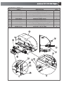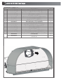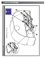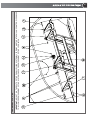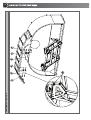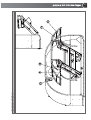
1
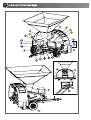
REVIEW: 2014/001
32000 bu/hr
USER’S MANUAL
OPERATION, MAINTENANCE AND SPARE PARTS
GTX 3230
GRAIN BAGGER
User’s Manual
Operation, Maintenance
and Spare Parts
Code: 130047
Edition: April 2014
Review: 2014/001
Due to the continuing improvements in the design and
manufacture of AKRON® products, MICRÓN FRESAR
S.R.L. reserves the right to modify components and/or specifications without prior notice.
GTX 3230 Grain Bagger
1. INTRODUCTION
This user’s manual describes the functions and
components of the AKRON® model GTX 3230
grain bagger. The machine’s operation and
maintenance instructions are detailed here, as
well as the necessary safety recommendations.
The information provided in this manual is
fundamental for the efficient and safe operation
of the machine. This documentation is included
in order to guarantee its optimal operation. This
is why this manual should be available at all
times either together with the machine or at least
within the operators’ and supervisors’ reach.
1-a. The Purpose of the Machine
The AKRON® GTX 3230 grain bagger is a
state-of-the-art machine for storing grain in
plastic grain bags according to cutting-edge
trends in this type of operations. This design
enables the machine to be completely
dismantled in order to minimize its volume for
transport between countries.
The machine’s simple design concept reduces
its maintenance requirements to a minimum and
guarantees its optimum operation under a
variety of conditions. However, it must be noted
that this grain bagger has been designed
exclusively for routine farm duties and that the
guarantee will be valid only as long as the
machine is used respecting the operation
procedures described in the present manual.
For operating this machine and for any
maintenance tasks or repairs, the instructions
given in the present manual and in any other
documentation supplied by the manufacturer
must be followed. Special attention must be paid
to safety precautions and recommendations, as
well as all the pertinent local Occupational
Health & Safety laws in force.
Any arbitrary modification carried out on the
machine or its components will release the
manufacturer from any responsibility arising
from damage or injury that may occur as a result
of such modification.
5
GTX 3230 Grain Bagger
7
2. INDEX
1. Introduction . . . . . . . . . . . . . . . . . . . . . . . . . . . . . . . . . . . . . . . . . . . . . . . . . . . . . . . . . . . . . . . . . ...5
1-a The Purpose of the Machine. . . . . . . . . . . . . . . . . . . . . . . . . . . . . . . . . . . . . . . . . . . . . . . . . . ...5
2. Index . . . . . . . . . . . . . . . . . . . . . . . . . . . . . . . . . . . . . . . . . . . . . . . . . . . . . . . . . . . . . . . . . . . . . . . ...7
3. Safety . . . . . . . . . . . . . . . . . . . . . . . . . . . . . . . . . . . . . . . . . . . . . . . . . . . . . . . . . . . . . . . . . . . . . . ...9
3-a Attitude Toward Safety . . . . . . . . . . . . . . . . . . . . . . . . . . . . . . . . . . . . . . . . . . . . . . . . . . . . . . . ...9
3-b"ATTENTION" Symbol and Signal Words . . . . . . . . . . . . . . . . . . . . . . . . . . . . . . . . . . . . . . . . ...9
3-c Personal Protective Equipment . . . . . . . . . . . . . . . . . . . . . . . . . . . . . . . . . . . . . . . . . . . . . . . . ...9
3-d Safety Warnings . . . . . . . . . . . . . . . . . . . . . . . . . . . . . . . . . . . . . . . . . . . . . . . . . . . . . . . . . . . ...9
3-e Risk Analysis . . . . . . . . . . . . . . . . . . . . . . . . . . . . . . . . . . . . . . . . . . . . . . . . . . . . . . . . . . . . . . ...9
4. Receiving the Machine . . . . . . . . . . . . . . . . . . . . . . . . . . . . . . . . . . . . . . . . . . . . . . . . . . . . . . . . .13
4-a Identification of your grain bagger . . . . . . . . . . . . . . . . . . . . . . . . . . . . . . . . . . . . . . . . . . . . . . .13
4-b Contact Information . . . . . . . . . . . . . . . . . . . . . . . . . . . . . . . . . . . . . . . . . . . . . . . . . . . . . . . . . .14
4-c General Comments on Grain Storage in grain bags . . . . . . . . . . . . . . . . . . . . . . . . . . . . . . . . .14
4-d Operation Principles . . . . . . . . . . . . . . . . . . . . . . . . . . . . . . . . . . . . . . . . . . . . . . . . . . . . . . . . .14
5. Preparation and Setup . . . . . . . . . . . . . . . . . . . . . . . . . . . . . . . . . . . . . . . . . . . . . . . . . . . . . . . .15
5.a Recommendations to Ease Subsequent Extraction . . . . . . . . . . . . . . . . . . . . . . . . . . . . . . . . .15
5.b Prior Checks in the Field . . . . . . . . . . . . . . . . . . . . . . . . . . . . . . . . . . . . . . . . . . . . . . . . . . . . . .15
5.c Prior Checks on the Machine . . . . . . . . . . . . . . . . . . . . . . . . . . . . . . . . . . . . . . . . . . . . . . . . . .16
5.d Machine Parking . . . . . . . . . . . . . . . . . . . . . . . . . . . . . . . . . . . . . . . . . . . . . . . . . . . . . . . . . . . .16
5.e Machine Positioning . . . . . . . . . . . . . . . . . . . . . . . . . . . . . . . . . . . . . . . . . . . . . . . . . . . . . . . . .17
5.f Adjusting the brake system . . . . . . . . . . . . . . . . . . . . . . . . . . . . . . . . . . . . . . . . . . . . . . . . . . . .17
5.g Grain bag Preparation and Mounting . . . . . . . . . . . . . . . . . . . . . . . . . . . . . . . . . . . . . . . . . . . .17
5.h Final Adjustments Before Starting the Bagging . . . . . . . . . . . . . . . . . . . . . . . . . . . . . . . . . . . . .20
6. Bagging Procedure . . . . . . . . . . . . . . . . . . . . . . . . . . . . . . . . . . . . . . . . . . . . . . . . . . . . . . . . . . . .21
6-a Operation Start-up . . . . . . . . . . . . . . . . . . . . . . . . . . . . . . . . . . . . . . . . . . . . . . . . . . . . . . . . . . .21
6-b Operation Parameters . . . . . . . . . . . . . . . . . . . . . . . . . . . . . . . . . . . . . . . . . . . . . . . . . . . . . . . .22
6-c Protection against Overloads . . . . . . . . . . . . . . . . . . . . . . . . . . . . . . . . . . . . . . . . . . . . . . . . . .22
6-d Interruptions During Bagging . . . . . . . . . . . . . . . . . . . . . . . . . . . . . . . . . . . . . . . . . . . . . . . . . . .22
6-e Operation at the End of the Grain Bag . . . . . . . . . . . . . . . . . . . . . . . . . . . . . . . . . . . . . . . . . . .23
6-f Closing the Grain Bag . . . . . . . . . . . . . . . . . . . . . . . . . . . . . . . . . . . . . . . . . . . . . . . . . . . . . . . .23
7. Maintenance . . . . . . . . . . . . . . . . . . . . . . . . . . . . . . . . . . . . . . . . . . . . . . . . . . . . . . . . . . . . . . . . .25
7-a Maintenance Schedule . . . . . . . . . . . . . . . . . . . . . . . . . . . . . . . . . . . . . . . . . . . . . . . . . . . . . . .25
7-b Maintenance after Receiving the Machine . . . . . . . . . . . . . . . . . . . . . . . . . . . . . . . . . . . . . . . .26
7-c Lubrication . . . . . . . . . . . . . . . . . . . . . . . . . . . . . . . . . . . . . . . . . . . . . . . . . . . . . . . . . . . . . . . . .26
7-d Replacement of Parts Subject to Wear . . . . . . . . . . . . . . . . . . . . . . . . . . . . . . . . . . . . . . . . . . .26
7-e Brake Fluid . . . . . . . . . . . . . . . . . . . . . . . . . . . . . . . . . . . . . . . . . . . . . . . . . . . . . . . . . . . . . . . .26
7-f Wear Prevention on Flexible Pipes . . . . . . . . . . . . . . . . . . . . . . . . . . . . . . . . . . . . . . . . . . . . . .26
7-g Tire Change . . . . . . . . . . . . . . . . . . . . . . . . . . . . . . . . . . . . . . . . . . . . . . . . . . . . . . . . . . . . . . . .26
8
GTX 3230 Grain Bagger
8. Machine Transportation and Storage . . . . . . . . . . . . . . . . . . . . . . . . . . . . . . . . . . . . . . . . . . . . .29
8-a Preparation of the Machine for Transport . . . . . . . . . . . . . . . . . . . . . . . . . . . . . . . . . . . . . . . .29
8-b Transportation . . . . . . . . . . . . . . . . . . . . . . . . . . . . . . . . . . . . . . . . . . . . . . . . . . . . . . . . . . . . . .29
8-c Machine Storage . . . . . . . . . . . . . . . . . . . . . . . . . . . . . . . . . . . . . . . . . . . . . . . . . . . . . . . . . . . .30
9. Specifications . . . . . . . . . . . . . . . . . . . . . . . . . . . . . . . . . . . . . . . . . . . . . . . . . . . . . . . . . . . . . . . .31
10. Product Dismantling and Disposal . . . . . . . . . . . . . . . . . . . . . . . . . . . . . . . . . . . . . . . . . . . . . .33
11. Guarantee Terms . . . . . . . . . . . . . . . . . . . . . . . . . . . . . . . . . . . . . . . . . . . . . . . . . . . . . . . . . . . . .35
12. Alphabetical Index . . . . . . . . . . . . . . . . . . . . . . . . . . . . . . . . . . . . . . . . . . . . . . . . . . . . . . . . . .37
13. Spare Parts List . . . . . . . . . . . . . . . . . . . . . . . . . . . . . . . . . . . . . . . . . . . . . . . . . . . . . . . . . . . . . .39
13-a Information for Obtaining Spare Parts . . . . . . . . . . . . . . . . . . . . . . . . . . . . . . . . . . . . . . .39
14. Parts subject to normal wear and tear . . . . . . . . . . . . . . . . . . . . . . . . . . . . . . . . . . . . . . . . . .81
15. User’s Notes . . . . . . . . . . . . . . . . . . . . . . . . . . . . . . . . . . . . . . . . . . . . . . . . . . . . . . . . . . . . . . . .83
GTX 3230 Grain Bagger
3. SAFETY
Even though the machine’s operation is simple
and safe, it is essential that all grain baggers
operators and supervisors read this user’s
manual and have an in-depth knowledge of its
contents. In this way, situations of danger will be
avoided for the operator, third parties and any
goods in the surrounding area.
There must be a written record of when the
operators are trained in every detail of the
machine’s operation.
3-a. Attitude Toward Safety
Just as with the operation of any other machine,
what is most important for preventing accidents
of any kind is the positive attitude of operators
and supervisors toward safety. As well as
observing the manufacturer’s recommendations
, the habit must be developed of foreseeing and
analyzing every possible contingency that could
arise during the operation of the machine. Even
though it is impossible to foresee all possible
situations, this habit helps to prevent the large
majority of hazardous situations.
3-b. "ATTENTION" Symbol and Signal
Words
Throughout the present manual, the
“Attention” symbol is used to indicate
risk situations for the operator, the
machine, other equipment or other
people.
This symbol will appear together with certain
signal words depending on the relative
seriousness of each risk situation.
DANGER: This identifies an imminent
hazardous situation whose consequences
may cause death or serious injuries if not
avoided.
WARNING: This identifies a potential
hazardous situation whose consequences
may cause death or slight to moderate injuries
if not avoided.
IMPORTANT: This describes a particular
situation where the machine could be
damaged or its normal operation could be
affected.
9
3-c. Personal Protective Equipment
Micrón Fresar S.R.L. recommends the use of
the following Personal Protective Equipment in
order to avoid any possible injury:
Personal Protective Equipment
Situation
Tractor
Driver
Operator
3-d. Safety Warnings
On different parts of the machine and on its
accessories you will find decals with accident
prevention symbols which must be considered
as part and extension of the instructions detailed
in this manual. Special care must be taken to
ensure these decals are present and legible
during the entire working life of the machine.
If for any reason any of these gets lost or
becomes illegible through wear, it is important to
replace
it
immediately,
indicating
its
corresponding code. To ask for a replacement
decal, please contact either the manufacturer
using the information given in 4-b “Contact
information”,or
your
local
Technical
Representative.
3-e. Risk Analysis
The risk situations that typically arise during the
operation of this machine are detailed below.
Recommendations are made that are of vital
importance for the safety of the machine
operators, of other workers nearby, and the
machine itself.
The pictograms used are taken from IRAM
standard 8075 “Tractors, agricultural and
forestry and green space maintenance
machinery - Safety signs and hazard pictograms
- General principles and features”. For more
details, their location on the machine is shown in
the following picture.
10
GTX 3230 Grain Bagger
DECALS
#
1
2
3
4
5
6
7
IMAGE
CODE NAME
Risk situations:
• During machine transport
114138 Particular recommendations:
• When transporting the bagging machine, stay below its speed limit for
safety reasons.
Risk situations:
• During machine transport
114200 • During bagging operation
Particular recommendations:
• Never stand or travel on the machine’s structure.
Risk situations:
• During bagging operation
114181
Particular recommendations:
• Keep a safe distance from the machine.
Risk situations:
• When operating the machine
016135 Particular recommendations:
• Observe the warnings indicated in the pictogram in order to avoid accidents
Risk situations:
• When operating the machine or performing maintenance tasks
114112 Particular recommendations:
• Carefully read the operator’s manual so as to become acquainted with its
features and operation.
Risk situations:
• During grain bag preparation
• When performing maintenance tasks
114122
Particular recommendations:
• Stop the motor and remove the key before performing setup or
maintenance tasks.
QTY
1
1
1
1
1
1
114150 Safety decals
1
065822 Cardan coupling position
1
9
Risk situations:
• During bagging operation
114152
Particular recommendations:
• Do not open or take away the safety protections while the motor is running.
1
10
114290 Identification plate
1
11
114128 Maximum 540 RPM
1
8
12
13
Risk situations:
• While uncoupling the machine from the tractor, the towbar lifts abruptly.
114187 Particular recommendations:
• Observe the pictogram’s indications by installing the support leg before
uncoupling the machine.
Risk situations:
• During bagging operation
114162 Particular recommendations:
• Do not stand within reach of the auger or introduce your hand while the
motor is running.
1
1
11
GTX 3230 Grain Bagger
#
IMAGE
CODE
NAME
QTY
14
Risk situations:
• During machine positioning
• During bagging operation
114132 Particular recommendations:
• Never use the driveshaft without its protector.
• Never cross over the driveshaft while it is coupled.
• Use, maintain or repair the coupling according to the manual’s indications.
1
15
Risk situations:
• When parking the machine on a slope
126750
Particular recommendations:
• Apply the brake to prevent the machine from moving.
1
114158 Maintenance
1
17
180109 Hydraulic Brakes
1
18
126226 Cradle latch
1
19
026315 Support leg
1
20
182120 Lifting jack
2
21
026227 Patent pending
1
22
026220 Left crank
1
23
026221 Right crank
1
24
025118 Hydraulic Pump
1
25
126223 Brake adjustment
1
26
126224 Risk of injury or accident.
1
27
126225 Cable clamp
1
28
128000 Important
1
16
12
GTX 3230 Grain Bagger
26
GTX 3230 Grain Bagger
4. RECEIVING
THE
13
MACHINE
The AKRON® GTX 3230 grain bagger is
delivered almost ready for operation. Only a
number of checks about issues related to
transport must be made upon receiving the
machine:
1) If the machine is delivered on a truck or
similar vehicle, check that all the slings and
elements used to fix the machine to the
transport are removed.
2) Check that the tire pressure is at the values
recommended in section 7 “Maintenance”.
3) Check that all the main machine components
are present and in good condition. The spare
parts list included at the end of this manual
makes a good checklist.
Figure 4.1
Identification plate
location.
4) All the safety guards and protections should
be present and in good condition (e.g., the
transmission cover on the tractor side, the
driveshaft cover, etc.).
4-a. Identification of your Grain Bagger
When ordering replacement parts or requesting
technical assistance or information, always
provide the following details for product
identification purposes:
• Model
Please fill in your machine’s data here for your
records:
MODEL:
• Mass (kg)
• Serial #
This information is engraved on the identification
plate located on the wheel chassis.
Please fill in your machine’s data here for your
records:
MASS (KG):
SERIAL #:
NOTE: The data, specifications and illustrations
in this manual are based on the information
available at the time it was written.
Due to the continuing improvements in the
design and manufacture of AKRON® products,
MICRÓN FRESAR S.R.L. reserves the right to
modify components and/or specifications
without prior notice.
Figures are only for illustration purposes, no
measures should be taken on the drawings.
14
GTX 3230 Grain Bagger
4-b. Contact Information
Should you need any further explanation
regarding the contents of this manual, please
contact us:
Micrón Fresar S.R.L.
Rosario de Santa Fe 2256
X2400EFN - San Francisco (Córdoba)
ARGENTINA
TEL.: ++54 3564 498502
E-mail: [email protected]
www.akron.com.ar
4-c. General Comments on Grain Storage
in Grain Bags
The storage of dry grain in grain bags is a
common practice among farmers, who see it as
a flexible and economical system for keeping
their grains, eliminating significant product
commercialization costs associated with third
party storage.
However, the effectiveness of this storage
system largely depends not only on monitoring
the condition of the grain inside the grain bag but
also on the procedure used when bagging the
product. This is why this manual includes
various guidelines for working based on
experience gathered from many farmers. Safety
precautions are also included, based on
analyses carried out according to current safety
laws for agricultural machinery of this type.
It is most important then to respect both the
order and the details of all the operations
explained, since the success of the bagging
operation in itself depends on this, as well as the
maintenance of adequate safety conditions for
the operators and all the equipment associated
with the bagging operation.
It is the responsibility of the user to study this
operations and maintenance manual, paying
special attention to all the warnings included in
each section and to the contents of section 3
“Safety”.
4-d. Operation Principles
The dry grain to be bagged, which is usually
provided by a self-unloading grain cart, enters
the grain bagger via its upper hopper; and an
auger conveys it to the inside of the grain bag.
The auger is driven by the PTO of a towing
tractor which moves forward coupled to the
bagging machine.
The grain exerts pressure on an inclined plane
located inside the bagging machine, and the
resulting force moves the machine and the
tractor coupled to it. The operating speed,
closely linked with the resulting tension in the
grain bag material, is adjusted by means of a
braking system built in to the bagging machine
which exempts the tractor from towing or
braking.
The following chart shows the main functions of
the machine and the components used to
perform each of them.
Function
Related component
or system
Grain intake
Receiving hopper
Internal grain
movement
Auger driven by
tractor PTO
Movement of the
bagging machine +
tractor together
Automatic movement resulting
from grain pressure on the
machine’s inclined plane.
Movement speed
adjustment
Built-in braking system
GTX 3230 Grain Bagger
15
5. PREPARATION AND SETUP
5-b. Prior Checks in the Field
5-a. Recommendations to Ease
Subsequent Extraction
The soil must be firm, completely clean and free
from remains of seeds, loose earth, weeds, etc.,
since otherwise the machine’s braking
conditions could be affected or the grain bag
integrity could be at risk. This would logically
have a negative effect on the correct conditions
for the product’s conservation. In the table
shown on next page, some precautions are
detailed regarding soil condition and its
influence on bagging quality.
The AKRON® model EXG 300 grain bag
unloaders AKRON® are ideal complements to
the AKRON® model GTX 3230 grain bagger,
and they require certain conditions in the
situation and preparation of the grain bags.
If the initial tie on the grain bag is made using
nailed boards or a plastic seal, less cereal will
remain after extraction to be removed manually
compared with using a rope tie (see paragraph
6-f “Closing the grain bag”).
Figure 1 shows that, if a grain bag is laid parallel
to a wire fence, a minimum of 4- meter space
must be kept between them, taking into account
that the extractor loads a vehicle moving on its
right-hand side from the point of view of the
tractor driver.
Preliminary ground preparation and cleaning are
extremely important, since they involve little time
and low cost but guarantee the integrity of the
grain bag and thus greater reliability of the
storage system.
5-c. Prior Checks on the Machine
It is essential for the machine to be in good state
of maintenance as per the recommendations
given in section 7 “Maintenance”. Nevertheless,
the following are some simple checks that
should be made prior to starting each grain bag.
• Tire pressure is a very important parameter,
since it determines the performance of the
machine, which works with permanent braking.
The pressure should be between 2.4 and 2.7 bar
(36 a 40 lb/pulg2) for adequate operation.
Figure 1- Minimum space between a grain bag and a wire fence
If grain bags have to be laid parallel to each
other as shown in Figure 2, at least 1 (one)
meter (3.25’) should be left between them in
order to work without difficulties during
extraction. In any case, as indicated before, the
most important precaution is to anticipate that
the first grain bag can be easily accessed from
the side on which the grain receiving vehicle
must move.
Figure 2 - Space between grain bags
• It is fundamental to visually check that all
accessories, locks, means of fixing, etc. are in
place and there are no loose, damaged or lost
parts. In any of these cases, the necessary
adjustments or corrections should be made
before operating the machine.
• All protections and safety covers should be
checked to be in their place and free from any
signs of wear that could hinder their functioning.
• It is advisable to clean all the machine
surfaces as thoroughly as possible to make the
work safer, since dirty surfaces become more
slippery.
16
GTX 3230 Grain Bagger
Precautions regarding
ground conditions
The selected place should be away
from trees and forest walls.
Importance and related risks
It is a good measure to reduce the risk of accidental breakage.
The ground must be free of weeds,
stubble, etc.
Imperfections on the ground could damage the bottom part of the grain bag
during bagging, which would make it more prone to attacks from rodents.
There should be no loose soil, leftover
grain, etc.
The braking capacity of the machine’s wheels would be affected and the grain
bag would therefore be filled at a tension lower than adequate.
There must be no steep level differences (holes).
If a wheel falls into a hole, the tray could touch the ground, pressing the grain
bag against the silo tunnel with the risk of tearing the silo bag.
The ground must be transversally level.
If the machine tilts to one side while operating, grain would accumulate on
one side of the grain bag and dangerous tensions would arise on the other
side.
The ground must be longitudinally level
(in the bagging direction).
The grain bag will “copy” any ground irregularity or imperfection, which can
give rise to air spaces that may locally affect product conservation conditions.
On sloping ground, the operating
direction must be against the slope.
Bagging must be carried out uphill for the grain bag to be filled in a more
controlled and even way.
5-d. Grain bagger Parking
a- Against the slope (Figure 4):
The machine, while not operating (unhooked
from the tractor), is designed to remain stable on
firm ground with a minimum slope of 8.5º. In
order for the machine to remain in a stable
position, before uncoupling it from the tractor, it
will be necessary to install the support leg as
shown in figure 3.
After following this procedure, apply the
hydraulic brake.
8,5º
Figure 4 – Bagging machine parked against a slope
b- Pointing down a slope (Figure 5):
Figure 3 – Support leg location
WARNING: When parking pointing down a
slope or against it, the brake must always
be applied (50 to 80 kg/cm2), or otherwise
the machine will move.
8,5º
Figure 5 - Bagging machine parked pointing down a slope
GTX 3230 Grain Bagger
5-e. Machine Positioning
The machine must be coupled to the driving
tractor by the towbar, as shown in Figure 6. For
safety reasons, the PTO should be connected
only after the grain bag has been mounted on
the machine.
17
re is reached. Adjust pressure by turning the
wheel clockwise or counter clockwise as
necessary.
Close the safety valve once the bags
manufacturer strech recommendation is
obtained.
WHEEL
WHEEL
Figure 6 - Bagging machine coupled to the tractor
For mounting the grain bag, the machine must
be coupled to the tractor, and the tractor’s hand
brake should be applied. The machine’s brakes
should also be applied. The handle operating
the hydraulic brake pump can be seen in Figure
7. The pressure applied to the brakes' hydraulic
system must be aproximately 90 bar.
Figure 8 - Functions of the kit valves
5-g. Grain bag Preparation and Mounting
Figure 7 - Hydraulic brake system
5-f Adjusting the brake system.
Follow next steps to properly adjust brake
pressure
PROCEDURE
1)Open the safety valve
2) Turn the wheel clockwise until desire pressu-
The following are basic instructions for grain bag
preparation, but it is essential to observe the
particular recommendations of the grain bag
manufacturer, since different or additional
precautions may be required.
The grain bag must be carefully removed from
its package and unfolded on the area where the
bagging will be started, which should be clean
and level as explained in paragraph 5-b “Prior
Checks in the Field".
Then the grain bag can be mounted on the
cradle as explained below.
18
GTX 3230 Grain Bagger
WARNING: When the tray is released and
lowered, care should be taken not to trap
the operator’s feet.
1) Connect the hydraulic hoses to lower the
hydraulic tray into its working position. The
hydraulic
tray
accepts
two
possible
configurations: Extended cylinder: it allows the
user to put the bag in position for working.
Retracted cylinder: working and transport
position.
Figure 11 – Cradle fastened by locking lever.
ATTENTION: Never stay on the cradle
trajectory while being lifted or lowered.
Failure to follow this instruction can cause
serious injuries to operator.
Figure 9 – Extended tray
3) Use the bag manufacturer middle-of-the-bag
mark to center the bag with the cradle. The
stretch marks stamped on the bag should
always be as shown in fig 13 (15 cm/ 6 inches
from the end of the cradle).
Figure 10 – Retracted tray
2) Remove the latch shown in figure 11 Then,
activate the electrical winch to lower the cradle
until reaching such a height to comfortably place
the grain bag on the lift (70 cm aprox).
Figure 12 – Cradle down in horizontal position
cradle
grain
bag
Figure 13- Positioning of the grain bag on the cradle
4) Activate the winch to lift the grain bag. Once
the bag is in contact with the machine tunnel, an
operator is required to put it into the tray and
slide it into the machine sides (figure 14). At the
same time the grain bag embraces the tunnel,
its bottom part should be supported by the tray.
Make sure the grain bag reaches the bottom of
the tunnel and all the folds are duly contained in
the tray.
GTX 3230 Grain Bagger
19
Figure 17 Elastic rope hole
Figure 14 Cradle in its highest position.
5) Once the grain bag has been lifted onto the
bagger tunnel, follow the instructions below:
Lift the rubber flap, as shown in figure 15.
1) Put the rope over the bag across the tunnel and
repeat the previous step.
2) Raise the tray into its operating position.
3) Take one of the fixed ropes and follow the
instructions below:
- Tie one of its ends to one of the rings in the tunnel
front.
- Tie it to the elastic rope.
Then, take it back towards the ring, and tie it to the
ring making sure the fixed rope is tightened enough.
-Repeat these steps with the three remaining fixed
ropes as shown in figure 18.
Figure 15 Rubber flap
Raise the tray until reaching half of its way.
Pull the bag from the folds until necessary (6
folds from the tunnel bottom).
Figure 18 Fixed ropes detail
Figure 16 Hydraulic tray
Put one of the braided elastic ropes through the hole
in the tray from top to bottom and tie it to the link in
its bottom part.
Figure 19 Ropes layout.
IMPORTANT: It is not necessary to
remove the cradle to start working.
20
GTX 3230 Grain Bagger
6) Before starting bagging, lower the rubber flap
as shown in figure 20 in order to prevent grain
from flowing back to the tray, that is, outside the
grain bag.
9) Close the end of the grain bag. Although the
grain bag manufacturer
usually gives
instructions, paragraph 6-f “Closing the grain
bag” offers general instructions on some of the
possible closing methods. Both the closing at
the front and at the end of the grain bag are very
similar, but the front end must always be rolled
downwards and held appropriately while the
grain bag starts to fill in order to prevent the end
from opening. This is necessary mainly due to
the air blowing effect caused by the auger and
the grain itself.
5-h. Final Adjustments Before Starting
the Bagging
Figure 20 - Rubber flap down
7) Level the machine by using the adjustable
towbar as shown in figure 21.
As indicated before, the machine driveshaft
should be coupled to the tractor PTO only after
the grain bag has been closed. Otherwise, the
operator would be working on preparing the
grain bag while the grain conveying auger is
accessible and coupled to the PTO, which would
involve a risk of being trapped in the case of its
accidental operation from the tractor. Keeping in
mind that the towbar is already linked to the
tractor, proceed as follows:
1) Release the end of the driveshaft from its
support on the bagging machine towbar as
shown in Figure 23.
Figure 21 – Bagger levelled with towbar.
WARNING: Before approaching the grain
conveying auger, check to see that the
driveshaft is disconnected from the
machine, in order to avoid accidental injuries
while the auger is being inspected.
8) Before continuing with the preparation of the
grain bag, check that the auger is completely
free from obstructions along the tube, i.e. that it
rotates freely. Figure 22 shows the front of the
auger.
Figue 23- Released driveshaft
2) Extend the driveshaft and couple the splined
end to the tractor PTO outlet shaft.
3) Fit the static plastic covers using the chains
and locks provided for this purpose. The
driveshaft should not be operated without these
plastic protectors being properly fixed in place.
All the safety warnings indicated on the
driveshaft must also be observed.
Figure 22 – Auger front
WARNING:
Always
uncouple
the
driveshaft if any maintenance tasks must
be performed on the machine.
GTX 3230 Grain Bagger
6. BAGGING PROCEDURE
6-a. Operation Start-up
With the machine and grain bag prepared as
explained in the previous section, the bagging
operation can be started following these steps:
1) Prepare the vehicle that will supply the grain
to be bagged (usually a self-unloading grain
cart). This vehicle’s discharge tube should be
arranged as shown in Figure 1. The grain
entering the bagging machine should fall as
directly as possible into the centre of the
receiving hopper. Otherwise, grain might hit the
opposite side of the hopper and spill out.
21
IMPORTANT: Always start up the PTO
before beginning to introduce grain into
the hopper in order to avoid over-loading
the auger.
WARNING: When grain enters the
receiving hopper and the grain bag end
starts to become stressed, the bagging
machine and the tractor will suddenly start
to move. The operators must be ready for
this moment.
6) Start feeding grain gradually, checking that
the end of the grain bag is adequately filled and
is lying evenly on the ground as shown in Figure
2. Remember that the front end of the grain bag
must be turned over.
DISCHARGE TUBE
Figure 2 - Filling of the grain bag front end
Stop feeding grain as often as necessary in
order to rearrange the end of the grain bag; it will
be impossible to correct its position once it is
fully loaded.
Figure 1 - Discharge tube position
2) Use a straight line as a reference along the
route of the grain bag in order to avoid bends in
its entire length. Otherwise, there is a risk of the
material being overstretched in some areas,
which might make it break later. Some
possibilities
are:
use
a
distant,
clearly-identifiable tree as a reference; lay a
string tensed along the route; keep a constant
distance from a wire fence.
3) Remember that both tires should be inflated
to a pressure within the range recommended in
paragraph 7. “Maintenance”.
4) Check that the initial pressure of the
hydraulic brake system is around 98.06 bar
(9806.6 kPa).
5) Gradually operate the tractor PTO until it
reaches its running speed, 540 RPM.
This initial control is very important so that the
stress in the grain bag material is even once
storage has been completed. The pressure on
the end of the grain bag must not be excessive.
Grain must keep its natural slope inside the
grain bag end so as not to exert excessive force
on the closure.
As the grain enters through the hopper, the
auger will convey it to the end of the grain bag
until the machine starts moving forward, pushing
the tractor. This is a very important moment: the
safety of the operators is the priority and care
must be taken that, when the machine starts
moving, it does not cause any injuries. The
movement of the grain feeding vehicle must be
coordinated so that grain continues easily
entering the receiving hopper of the bagging
machine.
22
GTX 3230 Grain Bagger
6-b. Operation Parameters
1) The machine’s braking force is directly related
to the resulting stress in the grain bag: the
pressure on the brakes should be adjusted so as
to make the best use of the grain bag’s storage
capacity, i.e. to apply the greatest possible
stress to the grain bag material according to the
manufacturer’s provisions. As shown in Figure
3, most grain bags have some kind of ruler or
indication printed on their surface that can be
matched with a measurement template supplied
by the manufacturer in order to determine the
degree of stress on the plastic material.
machine’s integrity and its correct operation. In
order to reestablish transmission, replace the
broken screw using the indications given in the
following table:
Walterscheid driveshaft
Size
Type
Surface
Quantity
protection
10.9
Zinc- or
Hexagonal
M8X1.25X60 DIN -ISO
cadmiumhead
931-960
plated
1
Bondioli & Pavesi driveshaft
Size
grain bag
Grade
Grade
Type
Surface
Quantity
protection
10.9
Zinc- or
Hexagonal
cadmiumM10x1.5x50 DIN -ISO
head
931-960
plated
1
If these screws break repeatedly, the causes
provoking this should be investigated.
Figure 3 – Ruler printed on the silo bag
It is safer to stay in the centre of the grain bag’s
stretching range so as to allow for further grain
settling.
2) Apart from checking this on the grain bag, it is
most important not to exceed 147.09 bar (14
709.9 kPa) in the hydraulic brake system. The
manometer has an indication of the operating
pressure range.
3) If, despite the precautions explained in 5-b
“Prior Checks in the Field”, the bagging machine
wheels skid due to wet ground or loose soil, the
pressure of the hydraulic brake circuit must be
reduced. As a last resort, if this is not enough,
the tractor’s brake can be used to contribute to
braking both machines, but the purpose of the
bagging machine wheels is to rotate, not to skid.
4) Make sure the grain bag is unfolded
gradually, one fold at a time.
6-c. Protection against Overloads
In the machine’s driveshaft intake there are
mechanical fuses, consisting of screws that will
break if there is any overload in the
transmission.
These screws should never be modified under
any circumstances, since they guarantee the
6-d. Interruptions during Bagging
If the bagging operation has to be temporarily
interrupted, this procedure will have to be
followed:
1) Stop feeding grain into the receiving hopper of
the bagging machine. The auger should be left
rotating in order to remove all the grain left
inside the receiving hopper and the conveying
tube.
IMPORTANT: Remember that the
receiving hopper drives the cereal toward
the auger. Do not use it for storage
purposes.
2) Wait for a moment until the auger conveys all
the remaining grain from the receiving hopper to
the grain bag. The tractor and bagging
machine will stop moving almost as soon as the
hopper and the conveying tunnel are emptied.
Operators should be ready for this sudden
stopping of the machine and the linked tractor.
3) By this time, the auger will be rotating
unloaded. Gradually, reduce PTO speed until it
stops, when the auger will also stop rotating.
GTX 3230 Grain Bagger
IMPORTANT: The auger should be
completely free of grain when it is
stopped, since any grain left there would
produce an excessive load on the auger
when it is started again.
4) Apply the tractor’s hand brake as well, to
make sure to prevent any grain bagger and
tractor additional unexpected movemet
5) If any maintenance, repair or inspection tasks
need to be carried out on the machine, uncouple
the driveshaft from the tractor PTO and prop it
on the towbar end support as shown in the
figure 4.
23
WARNING: If the tractor’s hand brake is
not in a good condition, when the bagging
machine brakes are released grain
pressure might push the bagging machine
and its linked tractor and the operators
would not be able to control it. It is best to
stop the tractor engine and leave it in a
low gear.
3) Once the bagging machine is properly held by
the tractor, release its own built-in brakes.
4) Gradually release the tractor’s hand brake
and use a low gear at the same time if
necessary. In this way, the pressure exerted by
the remaining cereal will push the bagging
machine-tractor assembly forward an additional
distance.
5) Tow the bagging machine using the tractor
until the portion of the grain bag left on the
machine’s silo tunnel is finally released. The
bottom end of the silo bag will then be
completely free to be closed.
6-f. Closing the Grain Bag
Figure 4 - Driveshaft propped on towbar end
6) If necessary to temporarily disengage the
tractor from the bagging task, remove the pin
from the tractor hitch.
WARNING: If the machine is left attached
to a semi-prepared grain bag and the
driving tractor is removed, care should be
taken that the pressure of the hydraulic
brake system does not fall. It is best to
place wedges on both sides of the
machine wheels in order to avoid
unexpected movements.
6-e. Operation at the End of the Grain
Bag
Most grain bags have some kind of indication
printed on their surface, e.g. a colored stripe, to
show that the bottom end is being reached.
When this kind of indication appears, or when
there are about 4 (four) grain bag folds left on
the silo tunnel, proceed as follows:
1) Follow instructions 1, 2 & 3 from the previous
paragraph, 6-d "Interruptions during Bagging".
2) Apply the tractor’s hand brake.
Both the front end of the grain bag and its
bottom end can be closed using different
systems (see paragraph 5-g “Grain Bag
Preparation and Mounting”). Instructions for
these can usually be obtained from the silo bag
manufacturers.
In general terms, the following grain bag closing
methods can be explained.
Plastic Closure
This consists of a strip split in two halves, male
and female, which trap both sides of a grain bag.
This is a high-quality and quick closing method.
This operation requires a special hand tool to
lock the plastic seal. Proceed as shown below:
Insert the end of the grain bag
into the “U” channel (female
half of the plastic closure).
Mould the grain bag material
until it fits into the “U” shape
and locate the male half of the
plastic seal.
24
GTX 3230 Grain Bagger
Place the special tool with its
roller in the centre of the seal
and press on the male half
until it is inserted into the
female half.
Fold the outside two fourths
downwards.
To close the seal completely,
the roller must be run from
one end of the width of the
silo bag to the other.
Continue folding the sides of
the end downwards.
Rotate the plastic closure 2 or
3 times, also winding the grain
bag.
Wooden Boards
This is an economical solution, in which the
materials to be used must be prepared
adequately to prevent a precarious closing from
causing an inadequate sealing. Do the following:
Arrange two wooden boards
on the end of the silo bag to
be closed.
Laterally fold the silo bag,
reducing its width so that the
boards cover all the material.
Join both boards checking
that the entire silo bag width is
pressed between them.
Nail the boards to each other.
Rotate the board assembly 2
or 3 times, also winding the
silo bag.
The sealing must have a
compact look.
Rope
This is a simple and economical method but it
involves a loss of length, since the silo bag must
be folded and turned over. The success of this
method depends on the operator's skill. Do the
following:
Visually divide the width of
the end of the grain bag into 4
(four) parts.
The grain bag end width will
thus be reduced.
Tie the “roll” thus obtained
with a rope located some 0.80
m (2.5’) from the end of the
grain bag.
Fold about 0.40 m (1.25’) of
this “roll” downwards.
Make a second tie with the
rope at the same height as the
initial tie.
If you are working on the initial
end, fold the tie so that it is left
under the grain as the grain
bag starts to fill.
When you are closing the initial end of the grain
bag, it must be held down properly with some
weight while it starts filling. This is necessary
due to the air blowing effect produced by the
auger, even before the grain enters the receiving
hopper.
GTX 3230 Grain Bagger
All the tasks indicated as “daily” should be
carried out before starting every workday, and
the ones indicated as “weekly” should also be
carried out when there is any significant change
in the conditions of work (change of silo bag,
change of grain).
7. MAINTENANCE
The machine is simple, so the only maintenance
tasks necessary are the following.
7-a. Maintenance Schedule
The following tables show the maintenance
tasks that have to be carried out periodically.
It is very important to keep a written record of all
the maintenance tasks performed on the
machine.
Daily Tasks
Condition
to check
General
machine
condition
Condition of the
conveying auger
tube
25
Normal situation
Correction method
Free movements in general, reasonable Eliminate causes of possible restrictions on the movements;
cleanliness of main components
remove any dirt that could hinder the machine’s operation.
Free from obstructions or excessive dirt
Eliminate possible obstructions or dirt left inside the tube.
Condition
to check
Normal situation
Correction method
Tire pressure
Between 2,4 and 2,7 bar (36 and 40
lb/pulg2), both tires at the same pressure
Adjust tire pressure
Weekly Tasks
Half-yearly Tasks
Condition to check
Normal situation
Correction method
Tightening torque for
the clamps holding the
lifting cable to the parallelogram assembly.
Clamp nuts tightened
Tighten the nuts, torque 2 kgm (20 Nm)
Condition of the hoist
steel cable
Not more than 3 wires cut on a single
strand.
Not more than 6 wires cut on all the
strands along an entire pitch.
Replace the cable as indicated in paragraph 7-d,
under the title “Hoist Cable Replacement”.
Silent rolling, free from bumps or
abnormal vibrations
Grease the bearings using the grease fittings supplied
for this purpose. Use NLGI grade 2 lithium grease. If
the problem is not solved, dismantle and evaluate
possible replacement according to the instructions
given in paragraph 7-d., under the title "Auger Support
Bearing Replacement”.
Operation of auger
support bearings
26
GTX 3230 Grain Bagger
7-b. Maintenance after Receiving the
Machine
1) Operate the winch until the cradle reaches the
ground. (cable should have no tension)
After some 30 hours of continuous operation, it
is essential to re-tighten all the machine’s
screws using the following torque values
recommended for SAE grade 5 zinc-plated
screws:
2) Remove the cable holders on each end of the
cable.
Size
1/ 4"
5/16"
3/ 8"
7/16"
1/ 2"
9/16"
5/ 8"
3/ 4"
Torque [ kgm - N.m
- 20
- 18
- 16
- 14
- 13
- 12
- 11
- 10
0,96
2,03
3,61
5,81
8,86
12,74
17,58
31,29
-
(ft.lb) ]
9,5
(7,03)
20
(14,81)
35,5 (26,29)
57
(42,22)
87
(64,44)
125
(92,59)
172 (127,77)
307 (227,40)
Aftert some 15 hours of operation check the
chain tension and adjust if necessary.
Chain tension:
Adjust the chain until the free strand can move
freely 3/8” to 5/8” (10 to 15 milimiters) using light
hand force.
3) Remove the old cable and place the new one.
This new cable should have the same
characteristics as the one used by the
manufacturer.
4) Lift and lower the cradle system several times
to check for proper cable installation
Auger Support Bearing Replacement
1) Identify the UC 209 bearing and release the
Allen studs that fix it to the rear shaft end.
2) Remove the hex head screws (3/4”) from the
support to remove it. Care must be taken to
prevent the auger from falling suddenly on the
support.
3) Insert the UC 209 bearing on the rear shaft
end. Then, position the support and tighten the
hex head screws (3/4") on the rear support.
4) Tighten the Allen studs that fix the bearing.
FREE STRAND
3/8” TO 5/8”
7-e. Brake Fluid
Brake fluid level should regularly be checked.
The tank should be at half point approximately.
Brake fluid should be Type 3.
7-f. Wear Prevention on Flexible Pipes
Take into account the following items for a better
use and take care of the flexible pipes included
in the machine.
Figure 1 - Proper chain tension
7-c. Lubrication
NLGI grade 2 lithium (multiple-purpose
automotive) grease is recommended for all the
lubrication points.
7-d. Replacement of Parts Subject to
Wear
Hoist Cable Replacement
• Visually inspect each one of the brake
hydraulic circuit components and hoses. They
should not have leakages: Keep them from
touching sharp objects. Do not tread on hoses
and keep them from being strangled.
• Be careful when working with brake liquid,
since it can cause burns on your skin and
wearing on metal parts.
• Check the helical cover on the hydraulic circuit
is in good condition in order to prevent the
operator from being splattered with fluid
GTX 3230 Grain Bagger
7-g. Tire Change
Follow the below steps:
1) Slightly loosen the wheel nuts.
2) Lift the machine using a mechanical or
hydraulic jack applied to the chassis in the
location indicated by the decal, as shown in
Figure 2.
Figure 2 - Support point for jack location
3) Once the bagging machine has been lifted,
install the assembled wheel and the five wheel
nuts .
4) Tighten the wheel nuts using a 1 1/2”
hexagonal wrench up to a final tightening torque
of 31.3 kg x m= 307 N x m= 227 lbs x ft.
IMPORTANT: Remember to re-tighten
wheel nuts during the first 3 weeks for
them to fit better on the wheel rims.
IMPORTANT: In case of inconvenience
with the sliding of the tray tracks, use a
brush to grease the sliding inner tube
with a thin layer of grease.
27
GTX 3230 Grain Bagger
8. MACHINE TRANSPORTATION
STORAGE
AND
8-a. Preparation of the Machine for
Transport
Once the grain bag has been released from the
bagging machine, prepare the machine for
transportation in the following way:
1) Uncouple the driveshaft from the tractor PTO
and put it on the towbar support.
29
8-b. Transportation
The bagging machine requires no special
configuration changes apart from the ones
explained in paragraph 8-a. “Preparation of the
Machine for Transportation”. Figure 3 shows the
machine ready for transport and also indicates
the towbar hitch. The maximum force that
should be exerted on the tractor hitch pin is 650
N. Brake hydraulic circuit should remain with no
pressure.
2) If not been done yet, lift the cradle and put the
latch.
TOWBAR HITCH
3) Raise the tray to the fullest.
4) Check both brakes are completely released,
i.e. there must be no pressure in the hydraulic
system.
5) If necessary, use the towbar (adjustable) to
adjust the machine inclination.
6) After coupling the machine to the tractor,
check the support leg is placed as indicated in
decal 026315. In the bagger without televeyor,
the support leg is placed in the chassis, rotated
upwards 180° (figure 1), whereas in the bagger
with televeyor it is placed in the towbar, rotated
upwards 90º (figure 2).
SILO TUNNEL
DETAILS
650 N
Figure 3 – Bagging machine ready for transport
IMPORTANT: The GTX 3230 grain
bagger is not designed for road travel.
Therefore, MICRON FRESAR S.R.L.
accepts no liability for accidents or
damage that may be caused during
transport if the machine is made to travel
on roads.
If the user still needs to do this, we
recommend
consulting
national,
provincial
and
municipal
safety
regulations in force in each region.
Figure 1 – Support leg - bagger without televeyor.
8-c. Machine Storage
Before storing the bagging machine, ensure that
the brake hydraulic system is left without
pressure. If the machine is expected to be
stored for several days, it is important to
adequately grease all the moving parts.
Figure 2 – Support leg - bagger with televeyor.
The machine must be stored indoors in a clean
and dry place, preferably with a cover to protect
it from dirt. If the bagging machine is to stay
outdoors temporarily, the lower auger cover
should be left open.
The loading capacity of the machine is based on standard grain
moisture (wheat at 13% moisture content). Bagging speed should
be slowed down when bagging grain at 17% moisture or higher,
otherwise the higher demand of horse power can break the PTO
overload shear pin. The PTO must always run at 540 rpm.
Transport position: No wheel configuration changes are required.
Towbar height adjustment: Enough to absorb differences in the
hitch.
Braking system: Hydraulic, with built-in manual pump.
Tube / auger: 20”.
Operation: 80 HP tractor equipped with a 540 rpm PTO.
Tunnel: For grain bags up to 10 feet.
Tare: 1900 kg (4188 lb).
Can fit a Ø 10 ft x 330 ft bag
32000 bu/hr capacity (bagger only).
9-a. List of Main Components
9. SPECIFICATIONS
DIMENSIONES
4080
2370
4510
GTX 3230 Grain Bagger
31
3670
GTX 3230 Grain Bagger
10. PRODUCT DISMANTLING AND
DISPOSAL
The following is meant to inform the user about
the steps to follow when the lifespan of the
machine, of its fluids or components comes to
an end. Dismantling and disposal instructions
are included.
• Metal parts or assemblies replaced or modified
for particular reasons such as corrosion or wear
should be properly disposed of. They should be
sent to scrap storehouses or foundries where
they can receive an adequate treatment. It is
essential to wear personal protective equipment
(safety gloves) when handling sheet steel.
• The system fluids which are periodically
replaced
(non-biodegradable
hydrocarbon-derived oils and greases) should
not be disposed of in the soil or in water
courses, since this would result in environmental
pollution. Up to now, the most usual application
for these wastes is to use them as fuel for vapor
generators (boilers) burning fuel-oil. They may
also be burnt is special waste-burning kilns.
Otherwise, they should be delivered to
companies authorized to handle and transport
them.
• Some practical use may be found for tires
when they are removed from the machine after
becoming worn out. Otherwise, they should be
taken to a tire-recycling centre for their
medium- or long-term integration into the
ecological cycle according to national, provincial
and municipal regulations in force.
33
GTX 3230 Grain Bagger
11. GUARANTEE TERMS
Micrón Fresar S.R.L guarantees the
AKRON® GTX 3230 grain bagging machine
for a one-year period since the date in which the
new unit is delivered to the customer.
This guarantee covers defects in materials used
to manufacture the machine, provided that the
grain bag unloader has been properly operated.
The
operating
procedures
considered
appropriate are those described in this manual.
This guarantee does not cover the following:
Damages or failures as a result of improper
operation or lack of machine maintenance that
may occur during transport, operation, or
parking from the delivery date.
Tires own guarantee.
Normal wear of parts due to their use. Their
replacement is part of the preventive
maintenance.
Micrón Fresar S.R.L is not responsible for any
repair made by third parties, or damages
resulting from this cause.
Micrón Fresar S.R.L, reserves the right to
modify the guarantee terms without previous
notice.
Micrón Fresar S.R.L. reserves the right to
modify specifications and designs without
previous notice and without the obligation to
implement these changes in the machines
already delivered.
Damages caused during machine operation by
any person whose abilities are affected or
reduced will not be covered.
If the machine is sold by the first owner within
the guarantee term validity, this will be
transferred to the new owner, provided that
Micrón Fresar S.R.L is advised by written
notice. Such guarantee will not be valid if the
current owner of the machine (not being the
original buyer of the product) has not advised
Micrón Fresar S.R.L in due time.
The guarantee will automatically become invalid
if any of the parts of the machine is modified or
replaced by spare parts not provided by Micrón
Fresar S.R.L. If such replacement or structural
modification was urgently necessary, the user
must obtain written approval from Micrón
35
Fresar S. R. L. to make such changes without
affecting these guarantee terms.
In order for the guarantee to come into force, it
is an essential condition to submit a request for
guarantee repair together with the following
information:
Name:
Date in which the damage occurred:
City:
Phone Number:
Machine Model:
Serial Number:
Invoice Number:
GTX 3230 Grain Bagger
12. ALPHABETICAL INDEX
Accessories 7
Storage 11, 12, 13 ,26, 27, 28
Parking 5, 14
Tray 14 ,20, 26, 27, 30
Driveshaft 7, 11, 20, 21, 27, 29
Change 23, 26, 27, 29
Chassis 11, 39
Closing 5, 13, 21, 22
Hydraulic Circuit 15, 20, 21, 28, 55
Contact 5, 7, 11
Ratchet (o hoist) 29, 41, 45
Transmission cover 29, 51
Disposal 6, 31
Dismantling 6,31
Quarterings 37
Bagging 5, 7, 12, 3, 14, 20, 21
Hitch 21, 26, 27, 29
Slings 11, 35
Grain Extractor 5, 13
Operation 12
Guarantee terms 6, 33
Identification 5, 11
Alphabeltical Index 35
Towbar 15, 21, 26, 27, 29, 45
Cleaning 13, 23
Brake fluid 5, 24
Lubrication 5, 23, 24
Maintenence 5, 8, 11, 12, 13, 21, 23
Micrón Fresar S.R.L. 7, 11, 26, 27
Mounting 5, 15, 20, 21
Motor 8, 21
Notes 57,58
Objective 3
Operator 7
Parameters 5, 20,
Bag Hanger 24, 26, 27, 30
Pictograms (decals) 7
Support Leg 14, 15, 30, 35
Platform 39
Preparation 13
Tire pressure 11, 13, 23
Receiving 5, 11, 12, 20, 21, 24, 29, 47
Replacement 5, 23, 24
Technical support 37
Spare parts 6, 11, 23, 24, 35
Wheels 53
Risk 7, 8, 14
Bearins 23, 24
Safety 3, 5, 7, 8, 11, 13, 15, 26, 27, 29, 35
37
Grain Bag 3, 5, 11, 13, 20, 21, 29
Rope 13, 22
Boards 22
Tasks 23
Tension 12, 14, 20
Turnbuckle 21,26, 27, 29, 30
Ground 5, 13, 14, 20
Lower Hopper 35, 41
Power take-off 12
Torque 24
Tractor 7, 11, 12, 15, 20, 21, 26, 27, 29
Transmission 11, 20,29, 49, 51
Transport 8, 11, 12, 20, 21, 23, 24, 26, 27,
29, 30
Tube / auger 29, 35
Tunnel 21, 24, 26, 27, 29, 30, 39
Speed 8, 12, 21, 29
Checks 5, 11, 13, 20
GTX 3230 Grain Bagger
13. SPARE PARTS LIST
All the components of the AKRON GTX 3230
grain bagger are detailed in the following pages.
To order a spare part for your machine, do the
following:
• Use the attached exploded diagrams, from
identify the component/s to be replaced.
• Note the code of each part and, if possible, the
name of each assembly.
• Order the spare parts from your nearest
AKRON® Technical Representative or to
AKRON® Spare Parts Service (see 13-a
“Information to Obtain Spare Parts”), indicating
each part's code and, if possible, the name of
each assembly.
• If replacing a part that originally included safety
decals, check that these are also present on the
replacement part.
13-a. Information for Obtaining Spare
Parts
AKRON® Spare Parts Service
Micrón Fresar S.R.L.
Rosario de Santa Fe 2256
X2400EFN - San Francisco (Córdoba)
ARGENTINA
Tel: +54 3564 498502
E-mail: [email protected]
www.akron.com.ar
The
nearest
AKRON®
Technical
Representative can also be contacted to obtain
machine components.
39
GTX 3230 ASSEMBLY
GTX 3230 Grain Bagger
ASSEMBLY STEP # 1
#
1
2
3
4
5
6
7
8
9
10
11
12
13
PART#
98.002.158051
98.309.101158
98.304.110158
98.002.095032
98.304.151095
29.39.28130
29.39.28838
29.29.30100
29.29.30200
98.002.127038
98.309.101127
29.42.28109
98.304.151127
DESCRIPTION
HEX HEAD SCREW G5 5/8" X 2" BSW
CADMIUM PLATED FLAT WASHER, 5/8"
LOCK NUT 5/8"-15 BSW
HEX HEAD SCREW G5 3/8" X 1 1/4" BSW
HEX LOCK NUT, 3/8" BSW
6 T HUB
BAGGER BRAKE DRIVE
CHASSIS + ASSEMBLED AXLE
CHASSIS AND TUNNEL
HEX HEAD SCREW G5 1/2" X 1 1/2" BSW
1/2" ZINC PLATED FLAT WASHER
COLUMN SUPPORT
LOCK NUT, G5 1/2" BSW
QTY.
8
8
8
6
6
2
1
1
1
8
16
2
8
43
44
GTX 3230 Grain Bagger
ASSEMBLY STEP # 2
#
1
2
3
4
5
6
7
8
9
10
11
12
13
14
15
16
PART#
98.304.151127
98.309.101127
98.002.127038
98.301.150127
98.310.100127
29.43.28372
29.39.27360
29.39.28336
29.43.80417
29.39.26343
98.002.095032
29.42.28371
98.304.151095
98.309.100095
98.002.127051
98.304.151127
29.42.28346
17
29.42.28358
DESCRIPTION
SELF-LOCKING NUT, G5 1/2" BSW (BAG N°1)
1/2" ZINC PLATED FLAT WASHER (BAG N°1)
HEX HEAD SCREW G5 1/2 X 1 1/2 BSW (BAG N°1)
HEX NUT G5 1/2" BSW
GROWER WASHER 1/2”
REVOLVING RING BUSHING W/ TELEVEYOR
AM-45 SUPPORT ASSEMBLY
TUBE-COLUMN ASSEMBLY
END BUSHING STOP WASHER
AM 45 SUPPORT WITH BEARING
HEX HEAD SCREW G5 3/8"x1 1/4" BSW
GRAIN DEFLECTOR W/ TELEVEYOR
LOCK NUT, 3/8” BSW
FLAT WASHER 3/8”
HEX HEAD SCREW G5 1/2” X 2” BSW (PACK N°9)
LOCK NUT G5 1/2” BSW (PACK N°9)
FRONT HOPPER UPPER PANEL FOR BAGGER W/
TELEVEYOR
FRONT HOPPER COVER FOR BAGGER W/O
TELEVEYOR.
QTY.
4
8
15
10
11
4
1
1
1
1
12
1
12
12
4
4
1
1
INNER DETAIL
ASSEMBLY STEP # 2
GTX 3230 Grain Bagger
45
ASSEMBLY STEP # 2
46
GTX 3230 Grain Bagger
GTX 3230 Grain Bagger
ASSEMBLY STEP # 3
#
PART#
DESCRIPTION
QTY.
1
29.42.27452
SIDE PANEL
2
2
29.42.27453
FRONT PANEL
2
3
29.42.26406
LOWER CORNER PLATE
8
4
29.42.27454
HOPPER ANTI-SPILL BRACE
4
5
29.39.27460
CROSSBAR
2
6
98.304.151079
LOCK NUT G5 5/16" BSW
80
7
29.42.27479
UPPER CORNER BRACE
4
8
98.002.079025
HEX HEAD SCREW G5 5/16" X 1" BSW
80
9
29.42.27476
OVERCAPACITY SIDE PANEL
2
10
29.42.27477
OVERCAPACITY FRONT/ REAR PANEL
2
11
98.309.100079
FLAT WASHER 5/16”
160
12
29.42.27455
OVERCAPACITY BRACE
4
47
48
GTX 3230 Grain Bagger
ASSEMBLY STEP # 3
98.846.028959
12
SIDE
PANEL
FRONT
PANEL
GTX 3230 Grain Bagger
49
CLAMPS FOR HOPPER ELECTRICAL WIRING
WIRING DIAGRAM 9
WIRING DIAGRAM 6
RIGHT SIDE VIEW
FOR HOPPER ELECTRICAL WIRING, IT IS
NECESSARY TO PUT 11 CABLE CLAMPS
INSTALLED AS SHOWN IN THE PICTURE.
98.365.027480: CABLE CLAMP, 3/8”
WIRING DIAGRAM 10
LEFT SIDE VIEW
50
GTX 3230 Grain Bagger
ASSEMBLY STEP # 4
#
PART#
DESCRIPTION
QTY.
1
2
3
98.002.079022
98.304.151079
98.309.100079
HEX HEAD SCREW G5 5/16” x 7/8” BSW
LOCK NUT G5 5/16" BSW
FLAT WASHER 5/16”
20
20
40
GTX 3230 Grain Bagger
ASSEMBLY STEP # 5
#
1
2
3
4
5
6
7
8
9
10
11
12
13
14
15
16
17
18
19
20
21
PART#
29.39.30540
29.39.28570
29.39.27550
98.304.110158
98.342.027568
29.39.28565
98.002.158102
98.002.158114
29.43.27577
98.002.158044
98.002.127102
29.39.28586
29.39.28585
29.39.27555
29.39.28567
29.39.28580
98.304.110127
98.002.127089
9.43.27579
29.39.27570
98.309.100158
DESCRIPTION
CRADLE
CRADLE LEFT SUPPORT W/LATCH
EASY-LIFT ARM
SELF-LOCKING NUT, 5/8"-15 BSW
CRADLE LEAF SPRING
CRADLE LEFT BRACE
HEX HEAD SCREW, G5 5/8" X 4" BSW
HEX HEAD SCREW, G5 5/8" x 4 1/2" BSW
CRADLE BUSHING
HEX HEAD SCREW, G5 5/8” X 1 3/4" BSW
HEX HEAD SCREW, G5 1/2" X 4" BSW
EASY-LIFT RIGHT SUPPORT
EASY-LIFT LEFT SUPPORT
EASY-LIFT ARM
CRADLE RIGHT BRACE
CRADLE PULLEY ASSEMBLY
SELF-LOCKING NUT, ½” BSW
HEX HEAD SCREW, G5 1/2” x 3 1/2" BSW
CRADLE LEAF SPRING BUSHING
CRADLE LATCH
FLAT WASHER 5/8"
QTY.
1
1
1
16
2
2
6
6
4
4
1
1
1
1
2
1
4
2
2
1
16
51
10
21
13
ASSEMBLY STEP # 5
FRONT VIEW
REAR VIEW
12
4
21
52
GTX 3230 Grain Bagger
ASSEMBLY STEP # 5
LOWER PARALLEL
LINK ARM
GTX 3230 Grain Bagger
53
ASSEMBLY STEP # 5
UPPER PARALLEL LINK ARM
54
GTX 3230 Grain Bagger
2
IMPORTANT: ADJUST ALL THE BOLTS OF THE PARALLEL LINK SYSTEM ALL THE WAY AND TURN THEM 360º COUNTER-CLOCKWISE
TO ALLOW FREE MOVEMENT OF THE SYSTEM. CHECK FREE MOVEMENT OF THE LOCK-LATCH .
ASSEMBLY STEP # 5
GTX 3230 Grain Bagger
55
ASSEMBLY STEP # 5
56
GTX 3230 Grain Bagger
ASSEMBLY STEP # 5
GTX 3230 Grain Bagger
57
58
GTX 3230 Grain Bagger
6 - ELECTRICAL WINCH INSTALLATION
-UNWIND AND REMOVE THE CABLE ROPE
FROM THE ELECTRIC WINCH.
- CUT THE CABLE ROPE TO A LENGTH OF
6.30 MTS.
-ATTACH THE CABLE ROPE HOOK TO THE
BOW SHACKLE.
GTX 3230 Grain Bagger
59
ONCE THE CABLE ROPE HAS BEEN PASSED
THROUGH THE HOLE AS SHOWN IN STEP #
3, GUIDE THE WIRE ROPE THROUGH THE
PULLEY AS SHOWN IN STEP #4.
ELECTRIC WINCH SUPPORT BOLTS:
98.037.095025: HEX-SOCKET HEAD CAP
SCREW, 3/8” X 1” BSW - QTY:3
98.304.151095: LOCK NUT G5 3/8" BSW QTY: 3
98.309.101095: FLAT WASHER, 3/8”
YELLOW ZINC PLATED QTY: 3
SET OF COMMERCIAL PARTS - BAG
Nº7 - 29.39.50227
60
GTX 3230 Grain Bagger
STEP 5
MAKE AN ADDITIONAL HOLE ON THE WINCH CABLE
ROPE DRUM. GET THE CABLE ROPE THROUGH THE
HOLES AND FIX IT WITH A STUD BOLT.
STUD BOLT
6-mm HOLE
CABLE ROPE
WINCH HOLE
ROTATE THE CABLE ROPE DRUM COUNTER
CLOCKWISE SO THE CABLE ROPE DOES NOT RUB
AGAINST THE HAWSE FAIRLEAD.
CABLE
ROPE
2
ELECTRICAL WINCH CONNECTION
INSTRUCTIONS
1 - CUT 1.25 M OF WINCH ELECTRICAL WIRE .
2 - PUT THE SEAL AND CONNECT THE TERMINAL
TO THE CABLE.
3
4
3 - INTRODUCE EACH CABLE INTO THE CONNECTOR CORRECT POSITION UNTIL MAKING A
CLICK “SOUND”. THE RED CABLE GOES IN POSITION “1” WHILE THE BLACK CABLE GOES IN
POSITION “2"
4 - ONCE THE CONNECTOR IS ASSEMBLED,
PRESS THE YELLOW PLASTIC SAFETY LOCK
INTO THE CONNECTOR UNTIL MAKING A “CLICK”
SOUND.
GTX 3230 Grain Bagger
ASSEMBLY STEP # 7
#
1
PART#
98.306.350190
DESCRIPTION
WHEEL NUT, WIDE FLANGE ¾” NF
LEFT TIRE/RIM ASSEMBLY
QTY
10
29.39.28140
(98.395.028142 RIM 13.00 CD FOR TIRE 400/60 - 15.5 -
1
98.662.028141 BKT TIRE, 400/60 - 15.5, 14-PLY)
2
29.39.28143
RIGHT TIRE/RIM ASSEMBLY
(98.395.028142 RIM 13.00 CD FOR TIRE 400/60 - 15.5 -
1
98.662.028141 BKT TIRE, 400/60 - 15.5, 14-PLY)
3
98.232.190062
HUB SCREW, 3/4" X 2" 1/2 NF
WHEEL
POSICIÓN
DEL
POSITION
NEUMATICO
CORRECT
CORRECTO
INCORRECT
INCORRECTO
10
61
62
GTX 3230 Grain Bagger
ASSEMBLY STEP # 8
#
PART#
DESCRIPTION
QTY.
1
2
3
4
5
6
98.002.095025
29.42.30215
98.310.100095
98.368.025512
99.389.202060
29.46.30216
HEX HEAD SCREW G5 3/8"X1" BSW
RUBBER FLAP SUPPORT
GROWER WASHER 3/8”
ELASTIC ROPE HOOK
ZINC PLATED CHAIN, Nº 60
BOTTOM RUBBER FLAP
18
2
18
9
0.75mts
1
1
2
3
4
5
6
GTX 3230 Grain Bagger
ASSEMBLY STEP # 9
#
PART#
DESCRIPTION
QTY.
1
29.43.30875
CYLINDER PIN
1
2
98.380.530060
DOUBLE R CLIP, Ø3 X 60
2
3
98.002.190114
TORN.C/EXAG.G5 3/4"X4 1/2" RW
2
4
98.002.127032
TORN.C/EXAG.G5 1/2x11/4" RW
4
5
98.301.150127
TUERCA HEXAG. G5 1/2"
2
6
98.304.350190
TUERCA AUTOF.G5 3/4" NF
4
7
98.198.095032
ROUND-HEAD SQUARE HEAD BOLT, G5 3/8" X 1"1/4 BSW
8
29.42.30772
RIGHT SIDE TRAY RETAINER
1
29.42.30771
LEFT SIDE TRAY RETAINER
1
9
98.309.100095
ARANDELA PLANA 3/8"
8
10
98.304.110095
TUERCA AUTOBLOC. 3/8" RW
8
11
98.378.030974
CYLINDER 2” / STROKE 925 MM
1
12
29.39.30780
SLIDING INNER TUBE ASSEMBLY
2
13
29.39.30751
WELDED TRAY ASSEMBLY
1
14
29.29.30750
HYDRAULIC TRAY ASSEMBLY
1
8
63
HYDRAULIC TRAY ASSEMBLY
64
GTX 3230 Grain Bagger
A
14
13
1
ASSEMBLY STEP # 9
2
B
3
A
B
12
4
5
11
C
6
7
C-B
C-A
10
9
8
9
7
10
GTX 3230 Grain Bagger
65
66
GTX 3230 Grain Bagger
TRAY HYDRAULIC CIRCUIT– WITHOUT TELEVEYOR - 29.39.30946
#
1
2
PART#
29.56.30944
98.378.060136
DESCRIPTION
TRAY - TRACTOR HOSE
ADAPTER, M/M 1/4" NPT X 9/16 JIC-REDUCED: Ø1.25MM
2
1
QTY.
2
2
GTX 3230 Grain Bagger
TRAY HYDRAULIC CIRCUIT
67
68
GTX 3230 Grain Bagger
ASSEMBLY STEP # 10
#
PART#
DESCRIPTION
QTY.
1
98.002.158044
HEX HEAD SCREW G5 5/8” X 3/4" BSW
16
2
98.309.101158
CADMIUM PLATED FLAT WASHER, 5/8".
32
3
29.42.28184
REINFORCEMENT PLATE BOLTED TO TOWBAR
2
4
98.304.110158
LOCK NUT 5/8"-15 BSW
16
5
29.29.28180
GTX ASSEMBLED TOWBAR
2
A
69
GTX 3230 Grain Bagger
ASSEMBLY STEP # 11
#
1
2
3
4
5
6
7
8
9
10
11
12
13
14
15
16
17
18
19
20
PART#
27.39.28829
29.43.27806
29.42.27807
29.43.27808
98.408.027809
98.395.027808
98.378.027811
98.378.027815
29.43.27804
98.378.071985
98.378.054501
29.43.27812
98.378.060135
98.311.112127
98.002.127044
98.395.025735
29.43.28820
98.378.020108
29.43.28818
98.378.071977
21
29.43.28817
22
23
24
25
26
27
28
29
30
31
32
33
34
35
36
29.43.28819
98.459.010015
98.378.013967
98.002.095032
98.304.151095
98.002.079019
98.173.039019
98.309.100039
98.310.100039
98.301.150039
98.061.063022
29.43.27810
98.378.027811
98.378.027815
98.304.151127
DESCRIPTION
WELDED PANEL
BRAKE PUMP SUPPLEMENT
BRAKE HANDWHEEL COVER
BRAKE PUMP SHAFT
BRAKE PUMP HANDWHEEL
DODGE BRAKE PUMP WITH F700 PISTON
PRESSURE GAUGE, 1/4” NPT
BRAKE PRESSURE CONTROL VALVE
BRAKE PUMP ACTIVATION NUT
FEMALE TEE FITTING, ¼’’ NPT
37º ELBOW JIC - RING
PERFORATED SCREW
NIPPLE ADAPTER, ¼’’ NPT – 9/16” NF
BEVELED FLAT WASHER, 1/2”
HEX HEAD SCREW, G5 ½ x 1 3/4” BSW
BRAKE CLAMP
PIPE HOSE – BRAKE PUMP
90º ELBOW, M 9/16” -18 UNF JIC/M 9/16”-18
HYDRAULIC PIPE CONNECTING TO BRAKE PUMP
TEE FITTING M 9/16” JIC/ M 9/16” JIC/M 9/16”
HYDRAULIC PIPE CONNECTING BRAKE PUMP TO
CALIPER
HOSE CONNECTING BRAKE PIPE TO CALIPER
ALUMINUM WASHER, Ø 10 mm, THIN FLANGE
ADAPTER, M-M 9/16”JIC – 3/8” NF
HEX HEAD SCREW, G5 3/8" x 1 1/4" BSW
HEX LOCK-NUT, 3/8" BSW
HEX HEAD SCREW, G5 5/16” X 3/4" BSW
ROUNDED HEAD SCREW 5/32” X 3/4"
FLAT WASHER, 5/32"
GROWER WASHER, 5/32"
HEX HEAD NUT, G5 5/32" BSW
STUD BOLT, G8 1/4" X 7/8" BSW
WHEEL KEY
PRESSURE GAUGE, 1/4" NPT
BRAKE PRESSURE CONTROL VALVE
SELF-LOCKING NUT, G5 1/2" BSW
QTY.
1
1
1
1
1
1
1
1
1
1
2
1
1
4
4
2
1
2
2
1
1
2
2
2
4
4
1
3
3
3
3
1
1
1
1
4
70
GTX 3230 Grain Bagger
ASSEMBLY STEP # 11
GTX 3230 Grain Bagger
ASSEMBLY STEP # 11
LOCATION
OF HYDRAULIC CIRCUIT
COUPLERS
POSICIÓN DE
LOS CONECTORES
DEL CIRCUITO
HIDRÁULICO
71
72
GTX 3230 Grain Bagger
BRAKE CIRCUIT BLEEDING
1- Connect the hose from the calipers to the fittings located behind the brake panel.
(4).
2- Remove the plug (3) and put the brake fluid provided by the manufacturer into the tank.
3- Open the bleed screw of the caliper further from the pump (5)
4- Close the switch valve lever (1) and turn the steering wheel (2) all the way counterclockwise (When
performing this action, slowly turn the wheel to allow oil to flow through the circuit).
5- Open the knob (1) and turn the steering wheel (2) all the way.
6- Repeat steps 4 and 5 until there is no sign of air in the fluid flowing through the bleed screw. If after
trying this process between 8 and 10 times, no fluid is observed to flow through the bleeder outlet,
check that the fittings located behind the brake panel are correctly engaged.
7- Close the bleed screw previously opened and follow steps 4 and 5 detailed above with the other
caliper (6).
SPARE PARTS - APPENDIX
GTX 3230 Grain Bagger
ASSEMBLY STEP # 12
#
PART#
DESCRIPTION
QTY.
1
29.39.30380
AUGER BEARING HOUSING
1
2
98.002.127038
HEX HEAD SCREW, G5 1/2” X 1 1/2” BSW
12
3
29.39.30360
ROLLER CHAIN ASA 80-2 1"
2
4
29.39.30445
10' BAGGER CHAIN COVER
1
5
25.43.25726
TENSION REGULATOR
1
6
29.39.30400
INLET SHAFT SUPPORT BOX
1
7
25.39.30730
ROLLER CHAIN TENSION SYSTEM 1/2”
1
8
29.42.28434
CHAIN COVER CAP
1
9
98.309.100063
FLAT WASHER 1/4"
5
10
98.002.063019
HEX HEAD SCREW G5 1/4" X 3/4" BSW
1
11
98.304.151063
LOCK NUT G5 1/4" BSW
1
12
98.408.014264
WHEEL KNOB, LTD 875 1833
1
13
98.301.150127
HEX NUT, G5 1/2" BSW
12
14
98.002.079025
HEX HEAD SCREW G5 5/16" X 1" BSW
7
15
98.342.025725
SPRING
1
16
98.002.063016
HEX HEAD SCREW G5 1/4" x 5/8" BSW
4
17
98.310.100127
GROWER WASHER 1/2"
12
18
98.309.101127
ZINC PLATED FLAT WASHER, 1/2"
2
19
29.43.27577
BUSHING
1
20
98.310.100158
GROWER WASHER 5/8"
1
21
98.002.158044
HEX HEAD SCREW G5 5/8” x 1 3/4” BSP
1
75
ASSEMBLY STEP # 12
19
20
21
76
GTX 3230 Grain Bagger
#
1
2
3
4
5
6
7
8
9
10
11
12
13
14
15
16
17
18
19
20
21
22
23
24
25
26
27
28
PART #
29.43.27381
29.43.30423
98.304.350254
98.713.214655
98.611.178084
98.611.176455
98.322.001200
29.43.30425
29.39.30360
25.43.30713
98.705.206530
25.43.21712
25.53.25710
25.43.25717
25.39.21732
29.43.27404
25.43.30424
29.43.30402
98.611.176152
98.705.207645
29.41.27401
29.43.27403
98.061.079032
98.301.150079
98.061.079025
98.077.079019
98.310.100190
98.002.190114
ASSEMBLY # 13
DESCRIPTION
BAGGER FRONT AUGER SUPPORT
AUGER SPROCKET, Z 24 ASA 80 DOUBLE
LOCK NUT, G5 1”-14 NF
2311 BEARING
SAV 10279 SEAL
SAV 10322 SEAL
SEEGER RING FOR Ø120 mm HOLE
AUGER BEARING HOUSING KEY
ASA 80-2 PITCH 1" CHAIN
CHAIN TURNBUCKLE COVER
6206 2RS BEARING
BEARING SPACER
SPROCKET, 1” Z 13
CONNECTING ROD COVER
CONNECTING ROD
SEAL SUPPORT BUSHING
DRIVE SPROCKET
SPLINED INLET SHAFT
SAV 7280 SEAL
6209 BEARING
10' BAGGER INLET SHAFT SUPPORT
BEARING SPACER BUSHING
STUD BOLT, G8 5/16" X 1 1/4" BSW
HEX NUT, G5 5/16" BSW
STUD BOLT, 5/16” 1” BSW G8
ALLEN SET SCREW, 5/16” X 3/4” BSW
GROWER WASHER 3/4"
HEX HEAD SCREW G5 3/4"X4 1/2" BSW
QTY
1
1
1
1
1
1
1
1
1
1
2
1
1
1
1
1
1
1
2
3
1
1
2
1
1
2
1
1
GTX 3230 Grain Bagger
77
GTX 3230 Grain Bagger
28
ASSEMBLY # 13
27
78
GTX 3230 Grain Bagger
ASSEMBLY STEP # 14
#
PART#
DESCRIPTION
QTY
1
98.002.079025
HEX HEAD SCREW 5/16" X 1" BSW
3
2
98.304.151079
LOCK NUT G5 5/16" BSW
3
3
29.42.25993
BOTTOM COVER HANDLE
1
4
29.39.28420
10-FOOT BAGGER INSPECTION COVER
1
5
29.43.25973
BOTTOM COVER HINGE PIN
1
6
98.334.030030
COTTER PIN, Ø3 X30 YELLOW ZINC PLATED
2
A
79
80
GTX 3230 Grain Bagger
ASSEMBLY STEP # 15 - 29.29.28130
#
PART#
DESCRIPTION
QTY
1
29.41.28129
6 T HUB / BRAKE DISC
1
2
98.730.330155
BEARING 30211
1
3
98.730.330945
BEARING 30209
1
4
98.303.310381
CASTLE NUT, 1 ½” NF
1
5
29.43.28131
WHEEL HUB WASHER
1
6
98.611.176970
SEAL, SAV 6657
1
7
8
9
10
11
98.232.190062
98.306.350190
98.334.050070
29.46.28133
98.460.310063
HUB SCREW, 3/4" x 2" 1/2 NF
5
5
1
1
1
WHEEL NUT, WIDE FACE ¾” NF
COTTER PIN Ø5 x 70
HUB COVER
ALEMITE, STRAIGHT-LONG, 1/4 NF
GTX 3230 Grain Bagger
LOOSE PARTS
#
PART#
DESCRIPTION
QTY
1
98.395.028170
AM 500 MECHANICAL JACK FOR AKRON GTX
3220 WITH TELEVEYOR
1
2
29.39.28175
AM 500 MECHANICAL JACK FOR AKRON GTX
3220 WITHOUT TELEVEYOR
1
3
29.39.28573
BRAIDED ELASTIC ROPE, Ø14
2
4
29.46.28580
ELASTIC ROPE FOR GRAIN BAG FASTENING
4
81
83
GTX 3230 Grain Bagger
14. PARTS
SUBJECT TO NORMAL WEAR AND TEAR:
Ordinary maintenance and spare parts replacement services of the parts detailed below are the
equipment owner’s exclusive responsibility, therefore, they will not be considered defects in material or
manufacturing, but rather defects due to normal wear and tear; improper operation or insufficient
equipment maintenance.
• Chains
• Augers
• Bearings
• Wheels
• Sprockets
• Brake System (brake pad ; shoe linings)
• Wear due to grain friction
Parts subject to improper operation or insufficient maintenance.
Using the gearboxes without normal oil level or not complying with the transmission inlet specifications
described in the user’s manual.
Altering the maximum inlet torque (shear bolt system on PTO).
MAXIMUN ALLOWED
INLET TORQUE
MACHINE
E 180 UNLOADER
EXG 300 UNLOADER
E 9250 FH BAGGER
E 9250 D BAGGER
E 9400 D BAGGER
GTX 3210 BAGGER
MAX 14 / 20 /22 / 24 /
GRAIN CART
PROBABLE CAUSES THAT CAN
ALTER THE MAXIMUM ALLOWED
TORQUE
Replacing the PTO’s shear pin with a
different bolt specification.
1860 N/m
6,5 / 8,5
MAX 28 / 25 GRAIN CART
GTX 3230 BAGGER
2130N/m
VERTICAL MIXER MXR 14
1600 N/m
Using a PTO that exceeds
maximum torque allowed by
machine.
the
the
Replacing the PTO with a PTO with no
shear pin device installed.
Wheel nuts: After around 30 hours of running or after changing a wheel, wheel nuts must be retighten
according to the torque values detailed in the manual (31.3 kg x m= 307 N x m= 227 lbs x ft. - point
7.g).
Special care should be taken to the wheel nuts tightening if the machine has moved over paths or
roads. Failure to follow these instructions may cause rim damage or lost of it.
GTX 3230 Grain Bagger
85
15. USER’S NOTES
......................................
......................................
......................................
......................................
......................................
......................................
......................................
......................................
......................................
......................................
......................................
......................................
......................................
......................................
......................................
......................................
......................................
......................................
......................................
......................................
......................................
......................................
......................................
......................................
......................................
......................................
......................................
......................................
......................................
......................................
......................................
......................................
......................................
......................................
......................................
......................................
......................................
......................................
......................................
......................................
......................................
......................................
......................................
......................................
......................................
......................................
......................................
......................................
......................................
......................................
......................................
......................................
......................................
......................................
......................................
......................................
......................................
......................................
......................................
......................................
......................................
......................................
......................................
......................................
86
GTX 3230 Grain Bagger
......................................
......................................
......................................
......................................
......................................
......................................
......................................
......................................
......................................
......................................
......................................
......................................
......................................
......................................
......................................
......................................
......................................
......................................
......................................
......................................
......................................
......................................
......................................
......................................
......................................
......................................
......................................
......................................
......................................
......................................
......................................
......................................
......................................
......................................
......................................
......................................
......................................
......................................
......................................
......................................
......................................
......................................
......................................
......................................
......................................
......................................
......................................
......................................
......................................
......................................
......................................
......................................
......................................
......................................
......................................
......................................
......................................
......................................
......................................
......................................
......................................
......................................
......................................
......................................