1
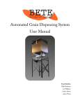
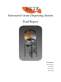
Automated Grain Dispensing System
Final Report
Team Members:
Mike Hofmann
Joe Willmott
Colton Davies
James Wood
Memorandum
To: Jeff Stephen
From: Team BETE
Re: Automated Lentil Bagging System
The final stage of the Automated Grain Dispensing System (AGDS) is now complete. Team
BETE is pleased to provide this functioning unit for you. We have fully tested each component
and the system and have concluded that it works to our satisfaction.
Team BETE is proud of our accomplishment and that we have completed the AGDS on time
and within budget.
2
Executive Summary:
The Automated Grain Dispensing System (AGDS) is a machine designed to expedite the
process of weighing and dispensing lentils into bags designated for sale by Saanichton Farms.
The process has been broken into multiple steps, with some steps being automated while
others are user actuated. Last year at Saanichton Farm, the bagging process required the
farm's matriarchs to weigh and label each bag. This process takes about 1 minute per bag and
we aim to reduce the time allocated to bagging the lentils to 15 seconds per bag. This year,
Saanichton Farm grew and harvested 8.5 tonnes of lentils on the Saanich Peninsula. With the
current volume of lentils, it would take approximately 125 man-hours to complete the task of
bagging this year's crop. Team BETE's goal is to reduce the time to 30 man-hours.
The AGDS consists of several key components including: the frame, vacuum, hopper, shaker
tray, weigh bucket, chute and electronics. Team BETE designed and assembled each part.
With the Automated Grain Bagging System, Team BETE strives to reduce the processing time
required to bring this product to market.
3
Table of Contents
Memorandum ............................................................................................................................. 2
Executive Summary: .................................................................................................................. 3
Table of Contents....................................................................................................................... 4
List of Figures or Illustrations: .................................................................................................... 5
Introduction ................................................................................................................................ 6
Discussion ................................................................................................................................. 6
Materials and Design ..............................................................................................................6
The Descent of the Lentil ........................................................................................................8
Electronics ............................................................................................................................10
System capabilities ...............................................................................................................11
Contributors ..............................................................................................................................11
Bagging the Conclusion ............................................................................................................11
Recommendations ....................................................................................................................12
References list ..........................................................................................................................12
Glossary of Terms.....................................................................................................................12
Appendices ...............................................................................................................................13
User Manual .............................................................................................................................13
4
List of Figures or Illustrations:
Figure 1.
Tin Tie Plastic lined Paper Bag with Window ............................................................6
Table 1.
Components and Material composition .....................................................................7
Figure 2.
Layout of Aluminum Metal to be cut at VICAMP ........................................................7
Figure 3.
FEA of ¾” plywood....................................................................................................8
Figure 4.
Slotted Iron Angle Frame ..........................................................................................8
Figure 5.
Lentils Being Sucked into Hopper. ............................................................................8
Figure 6.
Cross Section of the Inside of the Hopper. ................................................................8
Figure 7.
Hopper Chute showing UHMW plates. ......................................................................9
Figure 8.
Shaker Tray with Counter Weight. ............................................................................9
Figure 9.
Weigh Bucket with Acrylic Front. ...............................................................................9
Figure 10. Bottom Chute with Smaller Chute. ..........................................................................10
Figure 11. Control Box. ............................................................................................................10
5
Introduction
The Automated Grain Dispensing System (AGDS) is the brainchild of Saanichton Farm. They
realized that they required some type of automated system to assist in bagging their grains. In
2012, Saanichton Farm grew and harvested over 6000 pounds of lentils and each 2.5 pound
bag was filled, weighed and labelled by the matriarchs of the farm. The bagging process took
approximately 1 minute to complete one 2.5 pound bag using a scale and a scoop. In 2013,
Saanichton Farm harvested over 18000 pounds of lentils and the need for an automated system
was considered. If they continued to bag the lentils by hand, it would take the matriarchs about
125 man-hours to complete all 7500-2.5 lbs bags. With the AGDS, Team BETE wants to
decrease that time to under 40 man-hours. Team BETE plans to achieve this goal with a simple
yet amazing machine.
Jeff Stephen from Camosun College's Mechanical Engineering Department is our sponsor for
the project. When the project operates as specified then the machine will be sold to Saanichton
Farm.
Team BETE had several limitations for the project. The primary limitation was the cost of the
project which could not exceed over five hundred dollars. The location and size of the machine
were also to be taken into consideration since the machine could not exceed 84 inches in height
and 3 feet in length. Another limitation is the bag that was to be used. The tin tie plastic
window paper bag used by Saanichton Farm limited the size of bottom chute to be designed.
Considering the limitations that were incurred, Team BETE designed and manufactured a user
friendly machine.
Discussion
Once Team BETE was given their project, we began researching
other grain dispensing systems. Most common systems are for
large commercial enterprises or smaller manufacturers that had
robotic bagging units incorporated into the system.
Since
Saanichton Farm uses the tin tie plastic coated paper bag (Figure
1) with a window, we had to be more specific with our design. We
came across several coffee bean baggers that performed well and
in the same manner as we required.
The AGDS is designed to decrease the time spent bagging the
lentils at Saanichton Farm. The system consists of several key
components including the vacuum, hopper, shaker tray, weigh
bucket, chutes and the electronics. Each part of the system will beFigure
discussed
separately
in
1. Tin Tie Plastic
lined Paper
more detail.
Bag with Window.
Materials and Design
The design chosen is simple and most items can be purchased from Home Depot (other than
the electronics). Once we had a finalized design idea, we drew all the parts and 3D drawings in
6
Autodesk Inventor. Team BETE had to go through 2 iterations for the design as our first design
was rejected. Our first design package was rejected as it did not show a level of detail that was
required to manufacture proper parts. After a furious weekend of reconstructing each part we
assembled a design report that allowed us to begin fabrication. From the frame to the small
chute, each part in the system was scrutinized and had several iterations before the final design
was decided upon.
Purchasing of materials began minutes after we were given the go ahead to begin fabrication.
The slotted angle iron was purchased and assembled within 2 hours after approval. The sheet
metal was purchased shortly thereafter and we had arranged time on the water jet cutter with
Vancouver Island Centre for Advanced Manufacturing and Prototyping (VICAMP).
The main materials used for fabrication are:
Table 1. Components and Material composition.
Component
Material
Hopper
¾” plywood, laminate
Hopper chute
Aluminum, UHMW polyethylene
Shaker Tray
Aluminum
Weigh Bucket
Aluminum, clear acrylic
Frame
Slotted Angle Iron
Chute
Aluminum
Electronics
Many components
The aluminum that we selected for the project was 14 gage 5052 Aluminum since it was readily
available. According to Wikipedia, 5052 aluminum ‘...has good workability, medium static
strength, high fatigue strength, good weldability, and very good corrosion resistance, especially
in marine atmospheres.’1
In Inventor, once a part is created, it can be made
into a flat sheet for cutting purposes. This is a
useful function when used for sheet metal to
determine locations of folds and cuts where folds
are to occur. The flattened Inventor files were
transferred over to AutoCad so that they could all
be placed onto a single sheet of metal effectively.
The AutoCad drawing was saved as a DXF R12 file
type and sent to VICAMP for water jet cutting
(Figure 2). VICAMP prefers this file type for the
Figure 2. Layout of Aluminum Metal to be cut at
VICAMP.
7
water jet cutting. After we received the aluminum pieces, we bent the pieces with the help of
the staff in the Sheet Metal department at Camosun. Several attempts were made on 2 pieces
and it was advised that we make them into two or more pieces and rivet them together. All the
components were assembled together with rivets and except for the weigh bucket (see below
for more information).
For the hopper, Finite Element method (FEA) tests were done in
Autodesk Inventor to determine the stress concentrations on the
plywood (Figure 3). There was concern that the vacuum
pressure of 1-1.5 psi would implode the hopper. The inside area
is about 220 square inches so that gives about 220-330 psi of
pressure inside the hopper. Medium density fibreboard (MDF)
and 1/2 inch plywood were also tested using FEA but both
materials deflected too much to be considered as adequate
Figure 3. FEA of ¾” plywood.
material. We found that using 3/4 inch plywood would be
adequate in supporting the vacuum as well as the weight of the lentils in the hopper. We
designed the hopper to house 3 bulk bags of lentils with a total weight of
approximately 200 pounds. This volume was selected to maximize the
time spent bagging the lentils at a weight that the frame could support.
We chose 1.5 inch slotted angle iron for the frame and purchased a total of
56 feet in length. The frame also underwent FEA to determine if failure
would occur with 200 lbs of weight applied. The deflection calculated was
minimal which confirmed that we are able to use this product.
The Descent of the Lentil
Figure 5. Lentils Being
Sucked into Hopper.
Figure 4. Slotted Iron
Angle Frame
The process begins with the bulk lentil sack
positioned next to the AGDS. A suction hose (vacuum hose) inserts into
the hopper via the hole located on the left hand side of the hopper. A
secondary hole located at the top of the hopper houses the vacuum
hose going to the vacuum cleaner. After the user hooks up the
appropriate hoses into their locations, the user takes the uptake suction
hose and turns on the vacuum. The user inserts the nozzle of the
suction hose into the bag of lentils about one inch above the lentils
(Figure 4). This height allows for a steady flow of lentils entering into the
suction hose. The lentils get sucked up into the first stage of the AGDS:
the hopper.
The hopper holds a large volume of lentils raised off the ground to allow
gravity feed to move the lentils through the system. The hopper’s
construction of ¾” plywood with inner slopes aand a laminate lining
allows the lentils to flow with less resistance. The hopper was caulked to
Figure 6. Cross Section of8
the Inside of the Hopper.
reduce air leaks and vacuum loss since pressure loss is not desired. This design facilitates the
flow of lentils down into the hopper chute (Figure 5).
As the lentils travel out of the hopper, they come to the hopper chute. The lentils exit the
hopper through the hopper chute at the bottom of the
hopper. The hopper chute consists of the chute, the
↑
gate slide and ultra high molecular weight
UHMW
Plate
polyethylene (UHMW).
Two pieces of UHMW
sandwich the slide to reduce friction and wear and
tear rather than having aluminum slide on aluminum.
The chute gate performs two functions: to stop the
flow of lentils onto the shaker tray and to assist in
creating a vacuum when the hopper is filling. The
chute has an angled bottom of about 12 degrees that
approximates the same angle as the hopper tray.
Figure 7. Hopper Chute showing UHMW plates.
The angle controls the output of lentils onto the
shaker tray.
The lentils continue on their journey down the
chute and gravity feeds the lentils onto the
shaker tray (Figure 7). The shaker tray allows
a steady flow of lentils into the weigh bucket
through its motion in the horizontal direction.
The shaker tray mounts to the frame in the
back with a threaded rod and double bolted
and in the front by shock cord to allow
movement in the horizontal direction. The
shaker tray shakes using a 12 Volt DC motor attached to the outside of the tray’s sidewall near
the front. A counter weight attached opposite the shaker motor balances the tray. The lentils
vibrate out of the hopper chute onto the shaker tray and get shaken all the way down the tray.
The lentils cascade off the end of the shaker tray into the weigh bucket. If the shaker tray
achieves resonance then the lentils are thrown about off of the tray and do not behave as
necessary. Once the lentils cascade off of the shaker tray, they enter into the weigh bucket.
Figure 8. Shaker Tray with Counter Weight and Flowing
Lentils.
The aluminum weigh bucket has a clear acrylic front and
sits under the shaker tray. The weigh bucket catches the
lentils as they cascade off of the shaker tray. The bottom
of the weigh bucket attaches to the back of the weigh
bucket by a piano hinge to allow the bottom to drop down.
A Firgelli linear actuator, located on the right side of the
weigh bucket and mounted between the weigh bucket and
its bottom, regulates the throw of the bottom. Two support Figure 9. Weigh Bucket with Acrylic Front.
brackets located on each side of the bucket are bolted to the
frame. Strain gages attached to the end of the support brackets have the weigh bucket resting
on top. The strain gauges read the weight of the lentils in the weigh bucket. Once the correct
9
weight of lentils fills the weigh bucket, the shaker tray comes to rest and the lentils stop flowing
into the weigh bucket.
Nothing occurs until the user activates the switch under the bottom
chute.
The bottom chute sits is also mounted to the
frame and is located under the weigh bucket.
The bottom chute has two functions: to catch
the lentils flowing out of the weigh bucket and
to funnel the lentils into a smaller chute. The
smaller chute inserts into a tin tie plastic lined
paper bag that the user puts into place. Once
the user is ready, they activate the switch
located at the side of the bottom chute. The
switch connects through the Arduino to the
linear actuator and opens the weigh bucket
when pressed. Lentils descend down the bottom
Figure 10. Bottom Chute with Smaller Chute.
chute, through the smaller chute into the waiting
bag. The Firgelli operates on a time basis and after 5 seconds the weigh bucket bottom closes
again. Once the bottom closes, the shaker tray begins shaking allowing the lentils to cascade
into the weigh bucket and the process is started all over again.
Electronics
An Arduino Uno is the microcontroller behind the
automation and control for the bagging machine. The
analog and digital pins divide the controller into two
different systems,. Of the thirteen digital pins used, six pins
are used to power and display both the system settings
and weight readout on an LCD. The control box switches
connect via a pull-down switch which when pressed sends
5 Volts Direct Current (DC) to the controller signalling the
machine to run as commanded. Two signal input pins
connect to the linear actuator circuit. One pin operates the
motor circuit and the last pin controls the LED light to signal
when the weight bucket reaches at the correct weight.
Figure 11. Control Box.
The actuator circuit consists of an h-bridge and the Firgelli linear actuator. The h-bridge controls
whether the actuator extends to open the weight bucket via sending pin nine as high or set pin
eight high which retracts the actuator, in turn closing the bucket.
The motor circuit contains 3 separate parts: an opto isolator, a TIP 122 transistor, and the 12V
motor. The opto isolator is used to separate the 5V signal sent from the controller and 12 V
needed to run the motor. When the isolator reads an input from the Arduino, it outputs a 12 V
signal to the Tip 122 which allows 12 V to run through the motor in turn causing the motor to
spin.
10
The other side of the Arduino contains the analog pins. There are a total of four analog pins
being used in the bagging system. Two of these pins are used to read the two strain gauge
circuits. The potentiometer dial uses one pin and allows the user to select different grain
weights. The last pin receives a signal from the switch on the bottom chute. This switch is user
actuated and operates the linear actuator through the Arduino.
The strain gage circuit consist of two identical circuits which include the strain gauge and an
instrumentation amplifier. The amplifier consists of a positive and negative input, a 100 ohm
gain resistor, an output, power and ground. The positive and negative outputs from the strain
gage connect to the inputs of the amp which amplifies the difference between the positive and
negative inputs and sends it as an output to the Arduino.
System capabilities
The AGDS capabilities include and not limited to:
•
•
•
•
Filling the hopper with a 75 pound bulk bag in less than 3 minutes
Holding over 200 pounds of lentils in the hopper
Delivering 2.5 pounds of lentils into the shaker tray at a rate faster than the matriarchs
can weigh them by hand
Dispensing 10 pounds of lentils ready for bagging every minute
Contributors
We would like to thank your contributors to the project including:
•
•
•
•
•
•
•
•
•
Firgelli Automations for the donation of a linear actuator
Slegg Lumber for the discount on the plywood used in the hopper
McKillican Canadian Inc donated laminate for the inside of the hopper
VICAMP for their time and their water jet cutter
Camosun College's Carpentry department for cutting the plywood for us
Camosun College's Sheet Metal Department for aiding and educating us about sheet
metal bending
Our classmates for their suggestions and ideas to make a successful project
Saanichton Farm for letting us create this machine for them
Jeff Stephen for his time and patience and guiding us down the path of success
Bagging the Conclusion
Team BETE has produced an excellent grain bagging system for Saanichton Farm. The
versatility and ease of use will make this system a welcome relief to the farm. Team BETE is
proud of their creation and had a great time developing it from start to finish. From the frame to
the small chute, each part in the system was scrutinized and had several iterations before the
final design was decided upon. This process made for a superior product and it will survive the
test of time.
11
Recommendations
•
•
•
•
•
•
•
•
•
•
•
•
•
•
•
•
Ensure that all parts are designed and created well
Change the filter in the vacuum cleaner to either a foam filter or use a panty hose
instead of the cartridge filter (cartridge filter increases vacuum head loss)
Be proficient and have access to basic woodworking power tools. Straight and square
cuts are necessary to make the hopper go together as it should
Sealing the top of the hopper will be very forgiving due to the immense forces generated
on the walls of the hopper; simple closed cell foam will allow the lid to suck itself down
and auto-seal against the walls of the hopper
Apply heavy caulk to the hopper to ensure that it is sealed
Vacuum sealing is VERY important if you want to continue with the vacuum-uptake
theme. Make sure the valve at the bottom is precisely cut, and bolts up to the bottom of
the hopper dead-flat
Keep sheet metal parts as simple as possible
If complex parts of sheet metal are needed, if a part folds on itself, make it out of multiple
pieces
In the shaker tray, find the appropriate angle to allow for free flowing grain. Ensure that
the shaker tray is less than this angle. If greater, the grains will continue to fall into the
weigh bucket and add extra grain to each load. For example, for lentils on an aluminum
sheet, an angle greater than 220 caused the lentils to free flow
Also test the gap between the hopper chute and the shaker tray that will stop the flow of
grain. If there is too big of a gap the grain will pour out continuously; too small of a gap
and it will choke the system. Ideally include an adjustment system, like a threaded rod
attached to the hopper tray
Make sure you familiarize yourself with the Arduino platform and specifically motor
isolation
Try to reduce the noise from the shaker tray but not by too much as you still need
vibrations in the tray
Test different shaker motor weights to determine which is best to not hit resonance
Plan all mounting hardware for control electronics before starting the build
Make a printed circuit board.
Use a motor that has an appropriate speed and power rating for the shaker tray
References list
1. http://en.wikipedia.org/wiki/5052_aluminium_alloy
Glossary of Terms
Linear Actuator: A linear actuator is an actuator that creates motion in a straight line, in
contrast to the circular motion of a conventional electric motor.
12
Appendices
User Manual
13