1
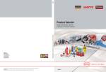
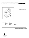
Pr
i
or
i
t
yManuf
act
ur
i
ng
Samur
ai
Oper
at
i
ngI
nst
r
uct
i
ons
Readt
hes
ei
ns
t
r
uc
t
i
onsbef
or
eus
i
ngt
hemac
hi
ne
JonDon | 800.
556.
6366 | www.
j
ondon.
com
MACHINE DATA LOG/OVERVIEW
MODEL _______________________________________
DATE OF PURCHASE __________________________
SERIAL NUMBER ______________________________
SALES REPRESENTATIVE # _____________________
DEALER NAME ________________________________
OPERATIONS GUIDE NUMBER ___________________
PUBLISHED __________________________________________
YOUR DEALER
Name: __________________________________________________________________________________________________
Address: _______________________________________________________________________________________________
For the name and address of your dealer contact: Windsor Industries
Phone Number: _________________________________________________________________________________________
2
*
TABLE OF CONTENTS
Machine Data Log/Overview. .........................2
Table of Contents ...........................................3
HOW TO USE THIS MANUAL
How to use this Manual..................................1-1
SAFETY
Important Safety Instructions.........................2-1
Hazard Intensity Level. ..................................2-2
Grounding Instructions...................................2-3
GROUP PARTS LIST
Base Group.......................................................................5-1
Label and Strap Group..................................................5-3
Pump Group.....................................................................5-5
Recovery Tank Group...................................................5-7
Solution Tank Group......................................................5-9
Vacuum Motor Group....................................................5-11
Wiring Diagram................................................................5-13
Notes ..................................................................................5-14
Warranty............................................................................5-15
OPERATIONS
Technical Specifications................................................3-1
Machine Operations.......................................................3-2
Pre-Run Inspection.....................................................3-3
Equipment Set-up.......................................................3-3
Cleaning & Emptying Tanks....................................3-3
Shut Down and Storage............................................3-4
MAINTENANCE
Daily Maintenance..........................................................4-1
Periodic Maintenance....................................................4-1
Monthly Maintenance.....................................................4-1
Semi-annually ..................................................................4-1
Lubrication.........................................................................4-1
Storage...............................................................................4-1
Solution Pump Replacement.......................................4-2
Vacuum Motor Replacement......................................4-2
Pump Replacement Kits...............................................4-3
Pressure Regulator.........................................................4-3
Machine Troubleshooting.............................................4-4
3
HOW TO USE THIS MANUA L
This manual contains the following sections:
-
-
HOW TO USE THIS MANUAL
SAFETY
OPERATIONS
MAINTENANCE
PARTS LIST
The HOW TO USE THIS MANUAL section will tell
you how to find important information for ordering
correct repair parts.
Parts may be ordered from authorized dealers.
When placing an order for parts, the machine model
and machine serial number are important. Refer to
the MACHINE DATA box which is filled out during
the installation of your machine. The MACHINE
DATA box is located on the inside of the front cover
of this manual.
The SAFETY section contains important information
regarding hazard or unsafe practices of the
machine. Levels of hazards is identified that could
result in product or personal injury, or severe injury
resulting in death.
The OPERATIONS section is to familiarize the
operator with the operation and function of the
machine.
The MAINTENANCE section contains preventive
maintenance to keep the machine and its
components in good working condition.
The PARTS LIST section contains assembled parts
illustrations and corresponding parts list. The parts
lists include a number of columns of information:
-
MODEL _____________________________________
DATE OF PURCHASE ________________________
-
SERIAL NUMBER ____________________________
SALES REPRESENTATIVE # ___________________
DEALER NAME ______________________________
-
OPERATIONS GUIDE NUMBER __________________
PUBLISHED ________________________________
The model and serial number of your machine is
located inside the base, directly above the pump.
-
REF – column refers to the reference
number on the parts illustration.
PART NO. – column lists the part
number for the part.
QTY – column lists the quantity of the
part used in that area of the machine.
DESCRIPTION – column is a brief
description of the part.
SERIAL NO. FROM – column indicates
the first machine the part number is
applicable to. When the machine design
has changed, this column will indicate
serial number of applicable machine.
The main illustration shows the most
current design of the machine. The
boxed illustrations show older designs. If
column has an asterisk (*), call
manufacturer for serial number.
NOTES – column for information not
noted by the other columns.
NOTE: If a service or option kit is installed on your
machine, be sure to keep the KIT INSTRUCTIONS
which came with the kit. It contains replacement
parts numbers needed for ordering future parts.
1-1
IMPORTANT SAFETY INSTRUCTIONS
When using an electrical appliance, basic precaution
must always be followed, including the following:
READ ALL INSTRUCTIONS BEFORE USING THIS MACHINE.
! WARNING:
To reduce the risk of fire, electric shock, or injury:
Use only indoors. Do not use outdoors or expose to rain.
Use only as described in this manual. Use only manufacturer’s recommended components and attachments.
If the machine is not working properly, has been dropped, damaged, left outdoors, or dropped into water, return
it to an authorized service center.
Do not operate the machine with any openings blocked. Keep openings free of debris that may reduce airflow.
This machine is not suitable for picking up hazardous dust.
Machine can cause a fire when operating near flammable vapors or materials. Do not operate this machine near
flammable fluids, dust or vapors.
This machine is suitable for commercial use, for example in hotels, schools, hospitals, factories, shops
and offices for more than normal housekeeping purposes.
Maintenance and repairs must be done by qualified personnel.
During operation, attention shall be paid to other persons, especially children.
When leaving unattended, secure against unintentional movement.
The machine shall only be operated by instructed and authorized persons.
When leaving unattended, switch off or lock the main power switch to prevent unauthorized use.
Do not handle the plug or machine with wet hands.
Do not unplug machine by pulling on cord. To unplug, grasp the plug, not the cord.
Do not use with damaged cord or plug. Follow all instructions in this manual concerning grounding the machine.
Do not pull or carry by cord, use cord as a handle, close a door on cord, or pull cord around sharp edges or
corners.
Do not pull/run machine over cord. Keep cord away from heated surfaces.
Connect to a properly grounded outlet. See Grounding Instructions.
SAVE THESE INSTRUCTIONS
2-1
HAZARD INTENSITY LEVEL
The following symbols are used throughout this guide as indicated in their descriptions:
HAZARD INTENSITY LEVEL
There are three levels of hazard intensity identified by signal words -WARNING and CAUTION and FOR
SAFETY. The level of hazard intensity is determined by the following definitions:
! WARNING
WARNING - Hazards or unsafe practices which COULD result in severe personal injury or death.
! CAUTION
CAUTION - Hazards or unsafe practices which could result in minor personal injury or product or property
damage.
FOR SAFETY: To Identify actions which must be followed for safe operation of equipment.
Report machine damage or faulty operation immediately. Do not use the machine if it is not in proper
operating condition. Following is information that signals some potentially dangerous conditions to the
operator or the equipment. Read this information carefully. Know when these conditions can exist. Locate
all safety devices on the machine. Please take the necessary steps to train the machine operating
personnel.
FOR SAFETY:
DO NOT OPERATE MACHINE:
Unless Trained and Authorized.
Unless Operation Guide is Read and understood.
In Flammable or Explosive areas.
In areas with possible falling objects.
WHEN SERVICING MACHINE:
Avoid moving parts. Do not wear loose clothing; jackets, shirts, or sleeves when working on the
machine. Use manufacturer approved replacement parts.
2-2
GROUNDING INSTRUCTIONS
THIS PRODUCT IS FOR COMMERCIAL USE
ONLY.
ELECTRICAL:
The amp, hertz, and voltage are listed on the
data label found on each machine. Using
voltages above or below those indicated on the
data label will cause serious damage to the
motors.
EXTENSION CORDS:
If an extension cord is used, the wire size must
be at least one size larger than the power cord
on the machine, and must be limited to 50 feet
(15.5m) in length.
GROUNDING INSTRUCTIONS:
This appliance must be grounded. If it should
malfunction or break down, grounding provides
a path of least resistance for electric current to
reduce the risk of electric shock. This
appliance is equipped with a cord having an
equipment-grounding conductor and grounding
plug. The plug must be inserted into an
appropriate outlet that is properly installed and
grounded in accordance with all local codes
and ordinances.
Improper connection of the equipmentgrounding conductor can result in a risk of
electric shock. Check with a qualified
electrician or service person if you are in
doubt as to whether the outlet is properly
grounded. Do not modify the plug provided
with the appliance - if it will not fit the outlet,
have a proper outlet installed by a qualified
electrician.
2-3
TECHNICAL SPECIFICATIONS**
ITEM
Electrical
Electric Vacuum Motor
Solution Pump
Solution Capacity
Recovery Capacity
Dimensions – Weight (Empty)
Dimensions - Length
Dimensions - Height
Dimensions - Width
Power Cable
3-1
10/29/01
DIMENSION/CAPACITY
230V 50HZ
DUAL 2 STAGE
100PSI
10 gal. (38L)
10 gal. (38L)
81 lbs. (37kgs)
31 in. (78.7cm)
35.5 in. (90.2cm)
17 in. (43.2cm)
25 ft.
(7.6M)
*
MACHINE OPERATIONS
Solution Tank
Solution Tank lid
Vacuum Tank
Vacuum Tank lid
Vacuum Inlet
Base Assembly
Dump Valve
Vacuum #2
Water Pump
Vacuum #1
Solution Outlet
Optional equipment:
89226 Deluxe Professional Wand
39605 Hose Asm, 1.5” Vac/Sol 25ft
3-2
MACHINE OPERATIONS
PRE-RUN INSPECTION
1.
2.
3.
Check all fittings and connectors for proper
assembly.
Check all hoses for leaks. Repair or replace any
damaged hoses.
Check power cord(s) for any damage. If
damaged, replace.
EQUIPMENT SET-UP
1.
2.
3.
4.
5.
6.
7.
8.
Plug power cord from machine into properly
grounded wall outlet.
Turn vacuum motor switch on and off to make
sure there is electrical power at machine.
Connect vac hose to machine. Slide the swivel
cuff over the outlet on the tank.
Connect the hose to your machine and
wand. Pull back the knurled collar on the quick
disconnect coupler and push onto the connection
on the chassis. To avoid leaks, check to be that
a positive connection was made.
Pour clean, hot water into the solution tank.
To avoid possible tank distortion, water
temperature must not exceed 140 F (60C).
Add a non-foaming cleaning solution
concentrate, for use in hot water extractors at
the proportions noted on the container (See list
below), into solution tank.
Turn pump and vacuum switch(s) to the on
position.
Start cleaning.
! WARNING
To prevent possible disease hazard, before
attempting to clean bodily fluids spills, you must
kill any viruses, germs or bacteria present in the
bodily fluid.
SUITABLE
INCOMPATIBLE
CHEMICALS
CHEMICALS
Alkalis
Aldehydes
Clorox II Bleach*
Aromatic Hydrocarbons
Defoaming Agents
Butyls
Detergents
Carbon Tetrachloride
Hydroxides
Clorox*
Oxygen Bleaches
Chlorinated Bleaches
Soaps
Chlorinated Hydrocarbons
Sta-Puf Fabric
D-Limonene
Softener*
Lysol*
Vinegar
Methyls (MEK)
Perchlorethylene (perc)
Phenols
Trichlorethylene
*Registered Trademark
3-3
CLEANING & EMPTYING TANKS
! WARNING
Always use defoamer if foaming occurs. Foam
will suspend large particles which may damage
vacuum as well as allow liquid into the vacuum
motor without activating the float shutoff.
1. Before proceeding, make certain that the nozzle
is functioning properly.
a. To check, hold the wand about one foot
above the surface to be cleaned and open
the wand valve. A full spray should be
observed from the nozzle.
b. If the nozzle is not showing a full spray
pattern, adjust nozzle for proper pattern,
clean, or replace nozzle.
2. Normally, chemical is applied on the push
stroke while vacuuming is done on the pull
stroke. For heavily soiled carpets the hand tool
may be used in the scrubbing manner, applying
chemical in both the push and pull stroke.
ALWAYS FINISH UP AN AREA WITH A VACUUM PULL
STROKE.
3. When cleaning, keep the working opening
(wand mouth) flat on the surface being cleaned.
Keep the wand moving when the valve is open.
4. The shutoff float inside the recovery tank will
impede the vacuum flow when the tank is full.
When this occurs, empty the recovery tank. Do
this by opening the dump valve located at the
front of the machine. NOTE: Dispose of waste in
a proper manner which would not violate any
Local, State or Federal law.
5. Once the recovery tank has been emptied, you
may once again proceed with cleaning
! CAUTION
Operating Vacuum after shutoff has activated could
draw water directly into the vac motor. This will
cause damage to the motor, therefore voiding your
warranty.
! CAUTION
ALWAYS TEST CARPET FOR COLOR FASTNESS IN AN
INCONSPICUOUS PLACE. Also, to avoid prolonged
drying times, do not spray too much solution in any
one area.
! WARNING
Before making any adjustments or performing
any maintenance to your machine, disconnect
the power cord from the electrical source.
MACHINE OPERATIONS
SHUT DOWN AND STORAGE
1.
2.
3.
4.
5.
Turn Switch OFF. Empty recovery tank
completely and rinse several times to remove
any dirt or debris that may be left behind.
Drain any unused cleaning solution from solution
tank and rinse with clean water to remove any
suds left behind by the cleaning chemicals.
NOTE: Dispose of waste in a proper manner
which would not violate any Local, State or
Federal law
Run a small amount of clean water through
pump if chemicals were used. This will help
insure the life of your pump.
Check the spray jet on the cleaning tool for full
spray pattern and inspect vac head for any
obstructions.
Remove as much moisture from system before
storing in cold climates. Excess water may
freeze during storage and crack internal
components, causing damage to the unit.
3-4
MAINTENANCE
DAILY MAINTENANCE
MONTHLY MAINTENANCE
Unplug power cord(s)
before servicing or
making any repairs.
1.
Flush the entire system, including floor tool,
hand tool, etc., with 1 to 3 gallons of clean, hot
water.
2. Vacuum out the solution tank.
3. Rinse tank with fresh water. Periodically inspect
the recovery tank and decontaminate if
necessary, using a Hospital Grade Virucide or a
1-10 bleach to water solution. Wastewater
should be disposed of properly.
4. Occasionally check filter screen at the bottom of
the solution tank and rinse clean with hot water if
necessary.
5. Inspect hoses for wear. Frayed or cracked
hoses should be replaced to avoid vacuum or
solution pressure loss.
6. Inspect power cord for wear or damage. This
cable will lie on wet carpet. To prevent electrical
shock replace cords that are frayed or have
cracked insulation immediately.
7. Clean all dirt and obstructions from drain valve
and gaskets to prevent possible leakage and
premature wear.
8. Run clean water through solution pump when
work is complete.
9. Empty both tanks and rinse, run vacuum (s) for
at least one minute to dry motor(s).
10. Store with access covers removed to allow tanks
to dry.
PERIODIC MAINTENANCE
1.
Twice a month, flush a white vinegar solution
(one quart vinegar to two gallons water) or antibrowning solution (mixed as directed) through
the extractor. This will prevent build-up of
alkaline residue in the system.
2.
If spray jet becomes clogged, remove the spray
tip, wash it thoroughly, and blow dry. NOTE: DO
NOT USE PINS , WIRE, ETC. TO CLEAN NOZZLE AS
THIS COULD DESTROY THE SPRAY PATTERN.
Apply silicone lubricant to solution nipple.
Periodically inspect all hoses, electrical cable
and connections on your machine. Frayed or
cracked hoses should be repaired or replaced to
eliminate vacuum or solution pressure loss. If
the cable insulation on the power cord is broken
or frayed, repair or replace immediately. Don’t
take chances with electrical fire or shock.
Clean outside of all tanks and check for
damage.
3.
4.
5.
4-1
1.
2.
3.
4.
Check all bearings for noise and wear.
Check all gaskets for wear and leakage.
Check pump pressure; observe spray pattern
and check gauge if necessary.
Check overall performance of machine.
SEMI-ANNUALLY
1. Check vacuum motor brushes .
LUBRICATION
For hose fitting lubrication, use a light silicone
lubricant which will not damage o-rings.
STORAGE
Thoroughly clean machine if it is to be stored.
Protect this machine from freezing while in storage.
Vacuum Motor Carbon Brushes Replacement (Windsor)
End Cap
Carbon
Brushes
WARNING: The green
ground wire must be
attached for safe
operation. See wiring
diagram.
If armature commutator is grooved, extremely pitted or
not concentric, the motor will need to be replaced or
sent to a qualified service center.
Important:
These brushes wear quicker as the length shortens due
to increased heat. Spring inside brush housing will
damage motor if brushes are allowed to wear away
completely.
3
[9.5mm]
8
Periodically check the length of the carbon brushes.
Replace both carbon brushes when either is less than
3/8" (9.5mm) long.
MAINTENANCE
Vacuum Motor Carbon Brushes Replacement (Ametek)
End Cap
Carbon
Brushes
WARNING: The green
ground wire must be
attached for safe
operation. See wiring
diagram.
Note: When replacing carbon brushes loosen wire
terminal BEFORE removing screws on bracket.
Only qualified maintenance personnel are to
perform the following repairs.
SOLUTION PUMP REPLACEMENT
1.
2.
3.
4.
Wire
Terminal
5.
6.
Note:
Place
stop in
groove.
If armature commutator is grooved, extremely pitted or
not concentric, the motor will need to be replaced or
sent to a qualified service center.
Wire Terminal
Turn off all switches and unplug the machine.
Unlatch the recovery tank from the base.
Tip recovery/solution tank to gain access to the
base of machine.
Remove solution hoses from fittings on pump.
Disconnect wires.
Remove the screws that fasten the pump to the
base.
Reverse process to install new replacement
pump.
VACUUM MOTOR REPLACEMENT
1.
2.
3.
4.
5.
6.
7.
Turn off all switches and unplug machine.
Unlatch the recovery tank from the base.
Tip recovery/solution tank to expose vacuum (s).
Locate the proper vacuum motor wires and
disconnect.
Unfasten screws holding vacuum to plate.
Remove the vacuum motor.
Reverse process to install vacuum motor
replacement.
Important:
These brushes wear quicker as the length shortens due
to increased heat. Spring inside brush housing will
damage motor if brushes are allowed to wear away
completely.
3/8 (9.5mm)
Periodically check the length of the carbon brushes.
Replace both carbon brushes when either is less than
3/8" (9.5mm) long.
4-2
MAINTENANCE
PUMP REPLACEMENT KITS 100 PSI
- FLOJET (65220)
DIAPHRAGM
29219
PUMP HEAD VALVE ASM
65204
84166
MOTOR 53246
PUMP REPLACEMENT KITS 100 PSI-SHURFLO (250-64B) PRIOR TO SN# 1000107206
250-67
Switch Asm
Pump Head Replacement
65187
4-3
Bypass Valve Asm
84161
Diaphragm
29206
MAINTENANCE
PRESSURE REGULATOR
For best results with the pressure regulator, we recommend that you clean and lubricate
the piston and u-cup with Superlube lubricant monthly or when pressure drop seems excessive.
1. Turn unit off before lubricating.
2. Remove cap, spring and spring retainer plate.
3. With fingertips remove piston and u-cup.
4. Wipe piston and u-cup clean of any film or scale.
5. Lubricate the piston and u-cup with Superlube.
6. Reassemble regulator.
7. With pump ON, re-adjust pressure regulator for normal operation.
LUBRICATE U-CUP WITH SUPERLUBE MONTHLY.
U-CUP
SPRING RETAINER PLATE
OUT
IN
PISTON
SPRING
(GOLD - 125 PSI)
CAP
4-4
TROUBLESHOOTING
PROBLEM
Loss of Power
Electrical shock
CAUSE
SOLUTION
Dead electrical circuit
Faulty power cord
Equipment not grounding
Receptacle not grounded
Check building circuit breaker or fuse box.
Replace
Follow grounding instructions exactly
Contact an electrician to check building’s wiring
Have a trained service technician check machine’s
wiring
Replace
Replace
Replace
Center and seal dome over tank
Replace or repair using acrylic plastic cement only
Internal wiring problem
Vac motor speed varies
or doesn’t run
Loss of vacuum
Worn motor brushes
Motor worn out
Faulty switch
Loose vacuum dome
Crack in dome of poor joint
Lint or dirt clogging
vacuum screen
Loose cuffs on vacuum
hose
Vac motor seals leaking
Floor tool vac chamber
clogged
Vac motor, hose, or dome
gasket
Pump inlet screen plugged
Pump air locked
Pump runs no solution
Pump runs, loss of
pressure
Pump will not run
Solution hose fitting
hard to connect
Carpet not getting
clean
Carpet too wet
Carpet browning
Solution not flowing
properly
4-5
Internal or external
solution line damaged and
leaking
Internal pump components
wearing out
Check BPR for particles or
cuts in seals
Unit not plugged in
Loose wiring
Corrosion on fittings.
Severe soil conditions
Over saturation
Leaving carpet too wet
Too much chemical
Light carpet with no brown
prevention
Solution hose connection
Faulty pump
Faulty floor tool valve
Faulty pump switch
With power off clean screen
Tighten cuffs turning counterclockwise
Replace
Wash out with hose. Pick lint out with a wire
Replace
Clean inlet screen
Press trigger to open valve on cleaning wand to
relieve air
Replace
Replace, see pump kit components (Pg 4-3)
Take piston from BPR and lubricate with Superlube. If
problem still exists change BPR.
Connect unit to 3 prong grounded outlet
See dealer
Clean with steel wool. Soak in acetic acid (white
vinegar). Lubricate lightly with silicone base lubricant.
Make several passes at right angles to each other.
Use a pre-spray.
Check solution wand. Make several passes without
spray
Check for loss of vac pressure
Check label for correct solution concentration
Go over carpet with browning prevent only
Check for positive connection
Repair or replace
Repair or replace
Repair
THIS PAGE LEFT BLANK INTENTIONALLY
4-6
BASE GROUP
3
2
15
2
3
20
3
1
2
21
3
19
4
18
5
17
22
16
15
6
14
13
12
3
8
7
11
3
9
8
5-1
10
BASE GROUP PARTS LIST
REF
1
2
3
4
5
6
7
8
9
10
11
12
13
14
15
16
17
18
19
20
21
22
PART NO.
57090
70015
87013
87095
140-05
280-02
040-03
57245
87080
57196
040-06
56-502068
32-900195
70595
50-501858
70532
08068
20008
280-03
46-802536
33-901006
57054
QTY
3
15
30
4
2
4
2
15
2
2
2
1
3
1
1
3
1
1
1
1
1
1
DESCRIPTION
NUT, 10-32 HEX NYLOCK SS
SCR, 1/4-20 X 3/4 HHCS SS NP
WASHER, 1/4 ID X 5/8 OD SS
WASHER, #10 FLAT PLTD
DRAW PULL LATCH STD.
RIVET AL. 3/16 X 1/2 CLOSED
CASTER SWIVEL 4" SWIVEL
NUT, 1/4-20 HEX NYLOCK SS
WASHER, .5 X 1.25 FLAT GR8 PLT
NUT, 1/2 PUSH-ON DOME CAP
WHEEL 8" BLK CENTERED HUB
AXLE ASSEMBLY, COMANCHE
SWITCH, DPST, LIGHTED ROCKER
SCR, 10-32 X 1" PPHMS
PL, EXTRACTOR 3 DWITCH BI
SCR, 10-32 X 1/2 PPHMS BLK NP
BASE, COMANCHE
CLAMP, 5/8 NYLON UL/CSA
RIVET ALUMINUM 3/16 X 3/4
HING, SOL & VAC TANK 4" X 8"
FILTER, INLINE 16A F55047/1
NUT, M8
SERIAL NO.
FROM
NOTES:
Latch Portion ONLY
5-2
LABEL & STRAP GROUP
3
4
2
1
5-3
LABEL GROUP PARTS LIST
REF
PART NO.
QTY
1
2
3
4
500568
500531
320-05
500009
1
2
1
1
DESCRIPTION
SERIAL NO.
FROM
NOTES:
LABEL, COMANCHE MAIN
LABEL, PROCHEM LOGO 6 X 1.75
VELCRO STRAP
LABEL, WARNING
5-4
PUMP GROUP
20
28
21
19
TO SOLUTION TANK
17
1
22
18
23
(A)
2
17
1
25
27
1
22
10
1
16
4
24
26
3
15
1
5
14
1
(A)
9
6
13
7
12
9
10
8
11
5-5
PUMP – GROUP PARTS LIST
REF
PART NO.
QTY
1
2
3
4
5
6
7
8
9
10
11
12
13
14
15
16
17
18
19
20
21
22
23
24
25
26
27
28
20042
39233
39403
12-800398
39250
40043
65220
31056
87018
57090
56012
390-09A
39599
70614
39597
22014
57104
14454
54182
62964
66017
70547
73505
64-950582
57040
87173
84181
140587
6
1
1
1
1
1
1
1
4
6
1
1
1
2
1
1
4
1
1
1
2
6
1
1
1
1
1
1
DESCRIPTION
CLAMP, 3/8 HOSE (D-SLOT)
HOSE, 3/8 RUBBER X 17"
HOSE, 3/8 RUBBER X 5"
HOSEBARB, "Y" 3/8 ALL NYLON
HOSE, 3/8 RUBBER X 12"
HOSEBARB, 3/8 MPT X 3/8 90D
FLOJET 100 PSI PUMP 220V
ELBOW, 3/8 MPT X 1/4 FPT
WASHER, #10 X 9/16 OD
NUT, 10-32 HEX NYLOCK SS
NIPPLE, 1/4 FPT QD
WASHER 9/16 S/S USS-THICK
HOSE, HP 23.0 1/4 MPT X 1/4 MPT
SCR, 10-32 X 1 1/8 PPHMS SS
HOSE, HP 15.0 1/4 MPT X 1/4 MPT
COUPLER, 1/4 F HEX
NUT, 10-32 W/STAR WASHER PLTD
BRKT, VALVE
MANIFOLD, ASM
PLATE, CM MANIFOLD
PLUG, 1/4 BRASS PIPE
SCR, 10-32 X 1 PPHMS BLK
STRAIN RELIEF, 1/2 NPT TRUMPET
CORD, MOLD ENGLAND 220V 25’
NUT, 1/2 NPT CONDUIT
WASHER, .765 ID X 1.31 OD X .09T SS
VALVE, BPR 125 PSI
BRKT, VALVE SFTY
SERIAL NO.
FROM
NOTES:
1000107206
5-6
RECOVERY TANK GROUP
1
16
2
15
14
13
12
3
9
4
5
11
3
6
8
7
5-7
RECOVERY TANK GROUP PARTS LIST
REF
PART NO.
QTY
DESCRIPTION
1
2
3
4
5
6
7
8
9
10
11
12
13
14
15
16
090-12A
78489
35256
260-33
140-05
370-06A
31032
70683
87257
OPEN
31002
81491
75378
35255
260-64A
70546
1
1
2
1
2
1
1
4
1
FLOAT CAGE ASSY COMPLETE SLIP
VAC, STACK ASM, COMANCHE
GASKET, DUMP VALVE
HOSEBARB, 1.5 MPT X 1.5
DRAW PULL LATCH STD.
DUMP VALVE 1-1/2 M THREAD
ELBOW, 1.5 FS X FS 45D PVC
SCR, 10-32 X 3/8 PPHMS SS NP
WASHER, HOSEBARB
1
4
1
1
1
6
ELBOW, 1.5 FPT X FS PVC
SET SCR, 5/16-18 X 1.5 CP SS
TANK, RECOVERY, COMANCHE
GASKET, TANK LID
ACCESS COVER CLEAR 6" W/RIM
SCR, 8 X 3/4 PFHT/S BLK ZINC
SERIAL NO.
FROM
NOTES:
5-8
SOLUTION TANK GROUP
14
1
2
3
13
12
4
11
5
10
9
6
8
7
5-9
SOLUTION TANK – GROUP PARTS LIST
REF
PART NO.
1
2
3
4
5
6
7
8
9
10
11
12
13
14
15
70222
56-502072
290-08
57023
87222
35182
40038
75379
56014
46-802536
70020
87013
56-502143
70384
43-807518
QT
Y
3
1
1
4
4
4
1
1
1
1
3
3
1
4
1
DESCRIPTION
SCR, #8 X 1/2 PPHST BLK
LID, SOLUTION TANK COMANCHE
STRAINER, 1/4 NPT 50 MESH
NUT, 5/16-18 HEX NYLOCK SS
WASHER, SEAL 5/16 X 3/4 OD
GASKET, FRAME
HOSEBARB, 1/4 MPT X 3/8 45D
TANK, SOLUTION, COMANCHE
NIPPLE, 1/4 CLOSE
HING, SOL & VAC TANK 4" X 8"
SCR, 1/4-20 X 1/2 HHCS SS
WASHER, 1/4 ID X 5/8 OD SS
BRKT, CORD WRAP NO HEATER
SCR, 1/4-20 X 1/2 PHTR BLK
GASKET, SOL-VAC TANK CMNCH
SERIAL NO.
FROM
NOTES:
1000089577
NOT SHOWN
5-10
VACUUM MOTOR GROUP
6
9
3
1
1
2
4
5
4
7
5
11
9
1
5-11
10
8
VACUUM MOTOR GROUP PARTS LIST
REF
1
2
3
4
5
6
7
8
9
10
11
PART NO.
87013
70011
43-807517
065-92
35166
70663
57245
56-502084
360-06
140216
140688
57105
70814
QTY
9
3
1
6
2
3
3
1
2
3
3
DESCRIPTION
WASHER, 1/4 ID X 5/8 OD SS
SCR, 1/4-20 X 5/8 HHCS SS
GASKET, VAC MTG.
VAC SPACER 2 1/4
GASKET, VAC MOTOR
SCR, 1/4-20 X 3 ¼ HHCS PLT
NUT, 1/4-20 HEX NYLOCK SS
BRKT, VAC MOUNT, DUAL 2 STG
VAC MOTOR, 230V 5.4 2ST TD
BRUSH SET, 230V VAC AMETEK
BRUSH SET, 230V VAC WINDSOR
NUT, 1/4-20 W/STAR WASHER
STUD, 1/4-20 X 4.5 SS
SERIAL NO.
FROM
*
NOTES:
SERVICE ONLY
SERVICE ONLY
5-12
WIRING DIAGRAM
5-13
NOTES
NOTES:
5-14
LIMITED WARRANTY
PROCHEM warrants your new machine to be free of defects in material and workmanship. This
warranty shall extend to the designated parts for the specific time period listed from the date of
delivery to the user. If PROCHEM receives notice of such defects during warranty period,
PROCHEM will either, at it’s option, repair or replace products which prove to be defective. Any
local or distant transportation, related service labor and diagnostic calls are not included.
Molded Components____________________________5 year (pro-rated)
Vacuum(s)____________________________________1 year
Pump________________________________________1 year
Hinges_______________________________________1 year
Rocker Switches_______________________________1 year
Heating Element_______________________________1 year
Wheels and Casters____________________________1 year
Fittings, hoses, o-rings, and other maintenance items are not covered under warranty.
This warranty shall not apply to defects resulting from improper operation, inadequate
maintenance by the customer, unauthorized modification, misuse, a unit that is
improperly repaired, or exposure to freezing temperature conditions.
To obtain warranty service, products must be returned to a service facility designated
by PROCHEM. Customer shall prepay shipping charges for products returned to
PROCHEM for warranty service and PROCHEM shall pay for return of the products to
customer.
PROCHEM makes no other warranty, either expressed or implied, with respect to this
product. PROCHEM disclaims the implied warranties of merchantability and fitness for
a particular purpose. Any implied warranty of merchantability of fitness is limited to
specific duration of this limited warranty.
This warranty gives you specific legal rights, and may also have other rights which
may vary from state to state, or province to province.
The remedies provided herein are the customer’s sole and exclusive remedies. In no
event shall PROCHEM be liable for nay direct, indirect, special, incidental, or
consequential damages, whether based on contract, tort, or any other legal theory.
Your PROCHEM unit is designed to give you years of reliable service. However, if a
problem should arise after the warranty period, follow troubleshooting procedures in
the operation and service manual. If you are still unable to determine the cause and
solution to the problem, contact your nearest distributor, factory representative, or
PROCHEM for details of the services available.
Components provided by PROCHEM, but supplied by other manufacturers, will only
be warranted to the extent that they shall be warranted to PROCHEM.
z 2002