1
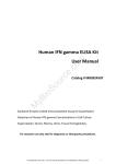
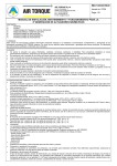
Service Manual
Chiller unit
MQH R 410A
Release Date
Rev
Review Date
november 2008
-----
-----
MQH R410A ELECTRONIC CONTROL
CONTROL PANEL
The control panel allows the user to carry out all the operations related to the use of the controller, in particular:
• To set the operation parameters
• To manage alarms
• To check the status
1
2
3
1
Display
2
Enter Key
Select the display value or to program and modify system values
3
Scroll Key
Scroll the menu
Display the status of the unit, entering/leaving water and ambient air temperatures,
compressor discharge pressure, setpoint, running times, alarm code, alarm history
etc.
1
TECHNICAL CHARACTERISTICS
1.1
ELECTRICAL PERFORMANCE
Maximum Rating
Item
Spec.
Rated input voltage
• 24 V, Single-Phase, 50 Hz or 60 Hz. Protected with on board fuse
Operating input voltage range
• 20.4 – 26.4 Vac
No damage input voltage range
• 16 – 32 Vac
Maximum current
• 0.5A @ 24Vac
Minimum power factor
• 0.92
Power consumption in stand-by
• < 5W
2
MQH 11/08
1.2
GENERAL SPECIFICATIONS
• The control box is in compliance with European current standard about emissions and immunity (e.m.c ).
• Flash memory is used to store the program, enable redownload via 10 bit A/D converter in factory and at
site.
• The miniCAC control board mounted in a IP20 plastic
case. The plastic is in compliance with UL94V0.
1.3
• During power failure with a duration more then 40
msec, the control goes off and will random restart after
power comes back according the dip 5 position.
COMPATIBILITY WITH OTHER PRODUCTS AND SYSTEMS
1.3.1 ELECTRICAL INTERFACES
Analogue Input
Digital Input
N°
Type
N°
Chiller
B1
NTC
ID1
Remote Unit Start/Stop
B2
NTC
ID2
Cooling/Heating mode selection
B3
NTC
ID3
B4
NTC/ratio
Fan motor overload
(or 2nd compressor protection)
B5
NTC/ratio
ID4
Compressor motor protection
ID5
Flow switch - Water diff. pressure switch
ID6
Low pressure switch
ID7
High pressure switch
ID8
Night Mode/Second setpoint
Digital output
N°
Chiller
Type of relay
(AC motor rating)
Type
1C-O
Compressor
2A @ 230Vac
N.A
2C-O
Fan high speed or 2nd comp
4A @ 230Vac
N.A
3C-O
Fans motor or low speed
See note 1
TRIAC
(see note 1)
4C-O
Antifreeze heater
2A @ 230Vac
N.A
5C-O
Reversing valve
2A @ 230Vac
N.A
6C-O
Pump
4A @ 230Vac
N.A
7C-O
Unit alarm relay
2A @ 230Vac
N.A
3
MQH 11/08
2
START-UP & OPERATING INSTRUCTIONS
ABBREVIATIONS
SYMBOL
DESCRIPTION
BMS
Building management system
C1
Compressor
CP
Condensing pressure
CSPT
Cooling setpoint temperature
CDCO
Cooling compensation offset
DEWT
EWT derivative DEWT = (EWT(t) – EWT(t-1))/dt °C/min
EP
Evaporating pressure
EWT
Entering water temperature
EWTM
Maximum entering water temperature
FP
Freeze protection (minimum LWT)
FS
Flow switch to detect sufficient water flow
HPC
High pressure cut-out
HSPT
Heating setpoint temperature
HDCO
Heating compensation offset
LO
Low fan speed
LOAT
Low level of the external temperature
LSL
Low speed limit
LWTM
Minimum leaving water temperature
LWT
Leaving water temperature
MCB
Main control board
NM
Night mode
OAT
Outdoor air temperature
OD
Outdoor
OFAN
Outdoor fan
PGI
Percent of glycol in the water
RC
Reverse cycle (heat pump)
RV
Reversing valve
SPT
Setpoint temperature
ST
Standard model (cooling only)
tC
Comp timer
TH
Trace heater for frost protection
Eph
Low pressure heating adjust
tD
Defrosting duration
THC
Coil heater
BYP
TXV by-pass during defrost
EPCR
Evaporating Pressure Calculation (function of OAT)
EPIC
Evaporating Pressure Iced Coil
EPCC
EP Clean Coil
OPEr
Parameter for mode selection in standard parameter
LOAt
OAT limit valve for THC activation
4
MQH 11/08
2.1
PRELIMINARY CHECK
2.2
The checks listed below shall be performed before starting the unit.
BEFORE START-UP
Before you start-up the unit, you must check the DIP switch
setup.
• Check the section of power supply and grounding
cables; make sure that terminals are tightened and
check the correct operation of contactors, with the
master switch open.
• Check that any voltage and phase variation in the
power supply dose not exceed the prefixed thresholds.
• Check that the components of the external water circuit
(user equipment, filters, power supply tank and reservoir, if any) have been installed properly, and according to the manufacture’s instructions.
• Check the filling of the hydraulic circuits, and make
sure that the fluid circulation is correct, without any
trace of leaks and air bubbles.
• Check that the direction of rotation of the pumps is correct, and that fluids have been circulating for at least
4 hours. Then, clean the filters on the suction side of
the pumps.
• Adjust the liquid distribution network in such a way
that the flow rate is within the specified range.
• Check that the water quality is up to the specifications.
• Check that oil heaters, if any, have been turned on at
least 4 hours before (it is mandatory if the temperature
is under 15 °C).
DIP SWITCH CONFIGURATION
DIP NO.
FACTORY
SETUP
POSITION OFF
POSITION ON
1
U BMS
MODBUS
2
Not used
3
No auto restart
Auto Restart after power failure
OFF
4
No OAT compensation
OAT compensation
ON
5
Cooling only unit
Heatpump unit
ON
6
No auto fan
Auto FAN
OFF
7
Pump ON when unit is ON
Pump always ON
OFF
8
Refrigerant R 407C
Refrigerant R 410A
ON
ON
OFF
** Turn ON the main switch of the power line.
5
MQH 11/08
Display
Description
C1
When compressor is operating
C1H
Compressor in heat mode
DEIC
defrost in operation
OFF
Off mode
COOL
Cool mode with no compressors on
HEAT
Heat mode with no heating on
2.3
STARTING AND USING THE UNIT
• During the normal operation, if the connection between No. 5 and No. 6 terminal is closed, the unit will
operate in heating mode. When the connection is
opened, the unit will operate in cooling mode. If connection 5-6 is open, then OPER mode can be selected
by display.
• To modify operative mode or the setpoints, press both
^ and > keys at the same time for 5s, then the “OPEr”
message appears on the display. The parameters are
scrolled using the ^ button and selected using the > button. When selected, the values can be changed by
using the ^ button to scroll from the present value to
max then min and can be selected by pushing the >
button.
After selection the menu will return to the beginning of
the same parameter change menu. If no button is pressed for 10s the display reverts back to normal mode.
• To start/stop the unit press for 5 secs the SCROLL key.
• To remotely stop the unit, open the connection between
No. 7 and No. 8 on the terminal board.
6
MQH 11/08
TABLE LIST OF STANDARD PARAMETERS
Display
Meaning
Min. value
Max value
Step
Default
value
OPEr
Cooling/Heating mode selection
COOL
HEAT
---
COOL
CSP
Cooling Setpoint
CSPL
23
0.5
12
HSP
Heating Setpoint
20
47
1
40
gLY
Glycol %
0
30
10
0
nigh
Night mode
1
4
1
2
COAL
CSPT compensation low limit
10
30
2
20
COAH
CSPT compensation high limit
20
36
2
30
CDCO
CSPT compensation
0
8
1
6
HDCO
HCSPT compensation
HOAL
HCSPT compensation low limit
0
15
1
8
-10
10
1
-5
HOAH
HCSPT compensation high limit
0
20
1
10
HPCE
1 auto reset for HPC alarm
0
1
1
0
ND
Night mode differential
0
15
1
2
NFC
Night mode fan change
-4
4
1
2
Id
Identification address
0
255
1
0
F0
Factory parameter
0
9
1
0
F1
Factory parameter
0
9
1
0
F2
Factory parameter
0
9
1
0
7
MQH 11/08
TABLE LIST OF FACTORY PARAMETERS
(DEFAULT VALUES ACCORDING TO DIP 8 SELECTION)
If you want to change the parameter value, you must get the password from the factory or your authorized service support.
Display
CSPL
Meaning
Minimum Cooling setpoint
Unit
Min. value
Max value
Step
Default
value R410A
°C
-5
14
1
8
FL
Fluid paremeter
0
2
0.5
0
CPL
Condensing Pressure Limit
bar
0
50
0.5
40
TC0
Min. condensing temperature
°C
0
100
1
20
TC1
Condensing temperature setpoint
°C
0
100
1
30
TC2
Max condensing temperature
°C
0
100
1
50
rpml
Min. Triac output
%
0
100
5
20
rpmh
Max Triac output
%
0
100
5
100
OAT1
Low OAT value in heating fan control
°C
0
50
1
15
OAT2
High OAT value in heating fan control
°C
0
50
1
30
LOL
EP protection correction in cooling
bar
0
1
0.2
0.4
EWTn
EWTM max EWT (only in cooling)
°C
16
40
1
24
Eph
Low pressure heating adjust
bar
0
1
0.1
0.3
tde
Defrost cycle maximum duration
min
2’
10’
1’
5’
dd
Delay time for defrost cycle
min
10’
60’
5’
35’
OCTi
OCT defrost start value
°C
-10
10
1
-3
OCTe
OCT defrost exit value
°C
5
30
1
12
CPe
CP defrost exit value
bar
15
40
1
34
EPi
EP defrost enter value
bar
1.8
10
0.2
5.4
COF
Off comp exiting defrost cycle
flag
0
1
0
b4
B4 analog input type
ntc
rAt
none
Ntc
b5
B5 analog input type
ntc
rAt
none
rAt
• During normal operation the current value of entering
water temperature is displayed flashing alternatively
with the current status. To display other useful data, go
to level 1, use the ^ button to scroll the menu, and use
the > button to select the display value.
8
MQH 11/08
DISPLAY DATA
PARA READING (PArA)
Code Parameter
HRS RUNNING HOURS (HRS)
Meaning
DE
TO (Triac output)
CSPT
cooling setpoint enabled
HSPT
heating setpoint enabled
tD
last defrosting time
Code Parameter
Meaning
C1
Compressor 1 running
hours x 10
tC1
Compressor 1 running hours
by the last reset
LOG LAST 10 ALARM (LOG)
SENSOR READING (SEnS)
Code Parameter
Meaning
EWT
entering water temperature
LWT
leaving water temperature
CP
discharge pressure
EP
suction pressure
CPS
saturated discharge temperature
EPS
saturated suction temperature
OAT
room air temperature
OCT
sensor temperature in coil
Code Parameter
Meaning
ALARM
see alarm list
STATUS READING (STat)
Code Parameter
C1
RV
ALARM CODE READING
Meaning
Compressor 1 on/off
REVERSING VALVE
Rv on = heating mode
Rv off = cooling mode
EH
ON or OFF
Pump
Pump on/off
OFAN
Fan on/off
Code Parameter
Meaning
dEIC
defrost in operation
ALARM
see last alarm exhisting
MODE
OFF or COOL or HEAT
9
MQH 11/08
• If an alarm is occurred, the alarm code is displayed,
but after 30’, even if the alarm is still active, the display
shows again the mode but “Alarm” message is displayed for 2’ every 10’ when an alarm is active.
When we enter in Alarm list, the first alarm code displayed is the last occurred.
ALARM SUMMARY
Fault as on display
2.4
Fault description
ADC
ADC error
CPF
CP transducer failure, out of range
EPF
EP transducer failure, out of range
REF
Refrigerant leak- low pressures
CPnc
CP transducer failure, no change error
EPnc
EP transducer failure, no change error
CFC1
CP and EP no change, compressor not operating (burn out or phase change)
EWTH
EWT entering water temperature sensor short circuited
EWTL
EWT entering water temperature sensor short disconnected
LWTH
LWT entering water temperature sensor short circuited
LWTL
LWT entering water temperature sensor short disconnected
OATH
OAT outdoor air temperature sensor short circuited
OATL
OAT outdoor air temperature sensor short disconnected
OCTH
OCT coil temperature sensor short circuited
OCTL
OCT coil temperature sensor short disconnected
HP
High pressure protection, automatic reset for first three times
HPC
High pressure cut-out
LP
Low pressure limit, unit cut out
LO
Leaving water temperature below allowed limits
HI
EWT is too high
FS
Flow switch opens, low water flow
CF1
CF1 input open, compressor 1 overload
OF1
OF1 input open, outdoor fan overload
PF
PF input open, pump internal overload
LOu
Low water volume
ConF
Not allowed configuration
CHECKING THE OPERATION
Check the following:
• The temperature of the water entering the evaporator.
• The temperature of the water leaving the evaporator.
• The level of the water flow rate in the compressor and
in case of stabilized operation.
• The fan's current absorption.
10
MQH 11/08
Check that the condensing and evaporation temperatures, during operation at high and low pressure detected
by the pressure gauges of the refrigerant, are within the
following range:
(on the units not provided with HP/LP pressure gauges for
the refrigerant, connect a pressure gauge to the
Schreader valves on the refrigeration circuit).
2.5
HP
Approx. 13 to 18 °C above the temperature of the air entering the condenser,
for R 410a units.
LP side
Approx. the difference between the temperature of the leaving water and saturated evaporating
temperature must be in the 2 - 4 °C for R 410a units.
SYSTEM DIAGNOSTICS AND OPERATION AT FAULT CONDITIONS
FAULT
RESPONSE
LWT sensor failure
If in cooling then stop machine
EWT sensor failure
Use EWT = LWT + 5
EWT & LWT failure together
Stop machine
OAT sensor failure
Use OAT = 35 (cooling) – 8 (heating).
Variable speed in heating always in maximum speed
CP sensor failure
Fans to max speed when OAT > 20 °C
Fans to low speed when 15 °C < OAT < 20 °C
If OAT < 15 °C, stop the unit in cooling only Disable vs.
In heating, end defrost only with OCT > OCTe or Td > Tde
EP sensor failure
In cooling mode, correct CSPT to CSPT > FP + 7
In heating, if OAT < 10 °C start defrost routine every 40 mins and end
defrost routine after 90 sec.
OCT failure or CP & OCT failure
In heating, if OAT < 10 °C start defrost routine every 40 mins and end
defrost routine after 90 sec.
Variable speed in cooling: always in maximum speed.
EP & CP failure
Stop the unit
11
MQH 11/08