1
O
Unlted States Patent [19]
[11] Patent Number:
Tsunoda et al.
[45]
[54] RADIO PAGING RECEIVER HAVING
[56]
Aug. 20, 1985
References Cited
DISPLAY CONTROL MEANS
U‘S PATENT DOCUMENTS
_
[75]
Date of Patent:
4,536,761
_
.
4,091,373
Inventors K?lllyukl Tsunoda; Yoshl? lchlkawal
5/1978
Nakamura ........................... .. 455/38
4,412,217 10/1983 Willard etal. ............... .. 340/825.44
both of Tokyo, Japan
FOREIGN PATENT DOCUMENTS
[73] Assignee:
Nippon Electric Co” Ltd” Tokyo,
2118337A 10/1983 United Kingdom ........... .. 340/3ll.1
I313311
Primary Examiner-Donald J. Yusko
Attorney, Agent, or Firm-Sughrue, Mion, Zinn,
Macpeak & Seas
[57]
ABSTRACT
[21] Appl. No.: 466,383
[22] Filed:
[301
Feb- 10, 1983
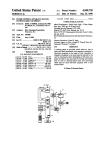
A radio paging receiver which generates an alert tone
and a message display on receipt of a selective calling
Foreign Application Priority Data
signal, includes a manually operated non-lock type
switch which generates ?rst and second control signals.
Feb. 12, 1982
Japan ................................ _. 57-19764
'rhe ?rst control signal stops the generation of the alert
[51] Int. Cl.3 ........................ .. H04B 5/04; H04Q 9/00
[52] US. Cl. ............................. .. 340/825.44; 340/799;
45 5/38
tone while the second control signal initiates a time-out
period after which the displayed message is turned off.
Depressing the switch produces the ?rst control signal
while its release produces the second control signal.
[58]
Field of Search ........... .. 455/38; 340/799, 825.44,
340/31l.1; 179/2 EB; 307/141
6 Claims, 11 Drawing Figures
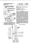
N0
IS
28
NR SWll'EN
BEPRESSED
15
SELECTIVE
CALLING SIGNAL
DETECTED
YES
I;
29
RECEIVE B ST NE MESSAGE I“
IS
NR SWITCH
IJEPNESSEB
:4
,5
2s
m1 svmcu
ELAPSE
as"
BEPRESSEB
510? count
0F TIIER
TURN OFF DISPLM
RETURN TO STEP ||
YE 5
YES
l5
NESSME BEING
INSPLAYED
US. Patent Aug. 20, 1985
4,536,761
Sheet 1 of3
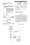
AMPLIFIER
RECEIVER
SECTION
WAVE FORM
DECODER
CIRCUIT
SECTION
FIGI
FIG, 2
CL
Q
IA
7.
__
DuDT“I ?r
4
4
N0D\I4/A
WM6N0
LWTL
3
.0
9W
m
U0s/
000
mA0 HO.4HB.
DO
W
m
Ew
0
ECCK m
MU
DnT/_|\48lR|.IL/EAV!_\EAE
U{MMRD.H
Du.
4I
WYAHVPLR0UAN
C
A
I
_
0
2E
4
A0AMTOI
®
W
m
UT.IT
WImIP0P4 I‘
W0T0NWPO
DlCAMTOlLvI0DUH4EPL
m
.A1
.|
C
DISPLAY
I LC DI
WnlVDIM_HVW5 0UMFL
DuE\I 0ICIE!C
M
U.S. Patent Aug. 20, 1985
Sheet3of3 .
4,536,761
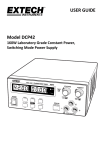
IT
RECETVING
'
OPERATTON
L
30\
READ OUT OF MEMO.
NEXT MESSAGE 8
DISPLAY lT
V
IST
DISPLAY MESSAGE
OF MEMORY l
STOP ALERT TONE 8T
TURN OFF DISPLAY
STOPTIMER
COUNT OF
i
RETURN TO STEP u E
V TS
ELAPSE
MR SWITCH
8 sec
DEPRESSED
YES (35
TURN OFF DISPLAY
STOP COUNT
T
OF TIMER
’
RETURN TO STEP IT I >
NO
TURN OFF DISPLAY
RETURN TO STEP IT
37
v
1
4,536,761
2
second control signals in response to respectively, the
RADIO PAGING RECEIVER HAVING DISPLAY
CONTROL MEANS
actuation and release of a switch.
BRIEF DESCRIPTION OF THE DRAWINGS
BACKGROUND OF THE INVENTION
Other objects, features and advantages of the present
invention will now be described in more detail referring
The present invention relates to a radio paging re
to the attached drawings wherein:
ceiver and, more particularly, to an improvement in the
control means for the display and alert tones.
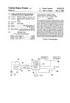
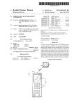
FIG. 1 is a schematic block diagram to show an em
bodiment of the radio paging receiver having user
friendly display control means according to the present
Radio paging receivers with display function in the
prior art generate alert tones upon reception of a selec
tive calling signal and store display information (or a
message) subsequent to the selective calling signal. The
invention;
alert tone stops when a switch is pressed down, and the
receiver shown in FIG. 1;
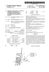
FIG. 2 is a block diagram of a decoder section of the
stored display information is simultaneously displayed
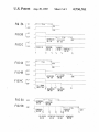
FIGS. 3A to SC, 4A to 4C, 5A and 5B are time charts
on a visual display device. Examples of such receivers
are disclosed in U.S. Pat. No. 4,091,373 issued to J.
Nakamura and also in US. Pat. No. 4,249,165 issued to
T. Mori and assigned to the assignee of the present
to explain the operation of the receiver shown in FIG.
1 and, more speci?cally, the control function for the
alert tone and the display at the times when the power
source is turned on, when a calling signal is received,
and when the receiver is waiting to receive the calling
application. In these radio paging receivers, stored dis 20
signal, respectively; and
play information can be displayed, when needed, by
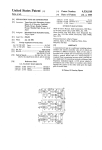
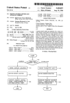
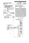
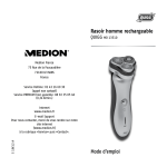
FIG. 6 is a ?ow chart to explain the operation of the
depressing a switch; however, as the switch is released,
receiver shown in FIG. 1.
the information on the display device immediately dis
appears. In order to con?rm the displayed information,
DESCRIPTION OF THE PREFERRED
the switch must be continuously depressed.
25
EMBODIMENT
In order to obviate such inconvenience, there has
been proposed a selective paging receiver provided
In FIG. 1, a radio calling signal received by an an
tenna 1 is ampli?ed and demodulated by a receiver
section 2. The demodulated signal is converted to a
with a timer which is activated when a switch is pressed
down to control the display on the display device by the
output of the timer. Reference is made to the Japanese 30 rectangular wave signal by a waveform shaping circuit
Patent Publication No. 55-2099 dated Jan. 18, 1980.
3 to be supplied to a decoder section 4. The calling
signal employed may be the one disclosed in US. Pat.
According to the system described in this reference,
manual operation of a switch can operate the receiver to
No. 4,194,153 issued to M. Masaki et a1 and assigned to
reset a sound circuit for alert tones and at the same time
the assignee of the present invention.
to activate a display device for a predetermined time 35
While the output from the waveform shaper circuit 3
preset by the timer function thereof. The receiver, how
is being fed to the decoder section 4, a preamble signal
ever, still is defective in that the information can not be
is ?rst detected, and then the battery saving function is
visually presented while the alert tone is present. Fur
suspended with the battery kept turned on. Then, as a
ther, if the time for the visual display is preset for a
word synchronization code is detected, the operation
predetermined short period of time, a longer informa
tion can not be displayed while if it is preset for a prede
termined longer period of time, a short information
unavoidably leaves a void space.
40
proceeds to the detection of the selective calling signal
assigned to the receiver in which the received calling
signal is compared with the one written in a program
mable read-only memory (P-ROM) 5. When the as
signed selective calling signal is detected, an alert tone
SUMMARY OF THE INVENTION
45 is immediately provided. A message signal subsequently
An object of the present invention is to provide a
following the selective calling signal is received at the
radio paging receiver having user friendly display con
same time.
trol means wherein a reset means for the alert tones and
The alert tone is ampli?ed by an ampli?er 6 to drive
a reset means for the display are separately provided so
a speaker 7. The message signal is fed to a display device
that an optimum time period for visual display can be 50 8, made of, for example, liquid crystal display (LCD)
set, thereby eliminating mistakes caused by overlooking
for display. As an end mark code is ?nally detected by
of the display or carelessness in switching-off the opera
the decoder section 4, the battery saving operation is
tion.
According to the present invention, there is provided
restored. The battery saving operation mentioned
above is substantially the same as the one disclosed in
a radio paging receiver having a display means, said 55 “Digital Radio Paging Communication System ” by
receiver comprising a ?rst means for detecting a selec
tive calling signal assigned to the receiver; a second
Masaki et al.'
In FIG. 2, a decoder 4 may be a single-chip central
means for storing a message signal transmitted subse
Drocessing unit (CPU), such as the microprocessor
quently to the selective calling signal; a third means for
p.PD7502 manufactured and marketed by the assignee
generating an alert tone in response to the output of the 60 of the present application, Nippon Electric Co., Ltd.
?rst means; a fourth means for displaying for a ?rst
The demodulated signal from the waveform shaping
predetermined time period the message signal stored in
circuit 3 is supplied to a data bus 402 through an input
the second means on said display means in response to
port 401. An output port 403 receives an instruction via
the output of the ?rst means; a ?fth means for stopping
the data bus 402 and provides address signals in order to
the generation of the alert tone in response to a ?rst 65 read out of the (P-ROM)5 a calling number data corre
control signal; a sixth means responsive to a second
sponding to the assigned selective calling signal. An
control signal for de?ning ?rst predetermined time
input port 404 receives the data read out of the PROM
period; and a seventh means for generating the ?rst and
5 and transmits the same to the data bus 402. An output
3
4,536,761
4
or 8 seconds after the time point t4 when the MR switch
port 405 receives an instruction via the data bus 402 and
9 is released. Even in the receiver with AAR function,
feeds an alert tone to the ampli?er 6.
if MR switch 9 is pressed within 8 seconds from the
A program counter 406 is activated as it receives the
input from the data bus 402 and supplies an address to a
tuming-on of the power switch, the alert tone immedi
program memory 407. Instruction group codes which 5 ately stops thereon and the display is automatically
are read out by the address, are supplied to a control
suspended by DAR function after 8 seconds from the
circuit 408. The control circuit 408 decodes the codes
release of the MR switch. The operation will become
and supplies control signals C to other blocks in order
identical to the one shown in FIG. 3B.
to carry out the instructions. An arithmetic and logic
In FIG. 3C, the MR switch is pressed down at the
unit (ALU) 409 executes arithmetic calculations, the
timepoint t2 within 8 seconds from the time point t1
result of which is stored in an accumulator 412. The
when the power switch is turned on and the MR switch
accumulator is also used for data exchange among the
is released at the time point t4. If the MR switch is
memory, input/output (I/0) ports, and registers. A data
pressed again within 8 seconds after its release or at the
memory 410 stores the content of the message signal
time point t5, the display is suspended therefrom.
which has been supplied from the input port 401 to the
data bus 402 subsequent to the selective calling signal.
The stored message signal is fed to LCD 8 via a display
control/driver 411 for a predetermined time by control
ling the timer housed in the data memory 410 for dis
play.
As illustrated in FIG. 2, a manual reset (MR) switch
9 whose operation will be described hereinafter, is con
nected between the input port 401 and, for instance,
ground.
15
Secondly, the control at the time a calling signal is
received will be described referring to FIGS. 4A to 4C
and 6. In the description hereinafter, the numbers to
indicate respective steps in the ?ow charts in FIG. 6
will be written in parenthesis after the explanatory
20 phrases or sentences. If a selective calling signal is de
tected (Step 12), a message signal subsequent to the
selective calling signal is received and stored (Step 13).
At the same time, the alert tone is emitted and the mes
sage signal is displayed on the LCD8 from the time
Although a non-lock type push-switch is assumed to 25 point t1 (Steps 14, 15), as shown in FIG. 4A. The 8
be used as the MR switch 9 in the following description,
second timer counters (called AAR and DAR timer
the MR switch may be any other non-lock type switch,
counters hereinafter, respectively) for the AAR and
such as a slide-switch of this type.
In the case where the receiver has alert tone autoreset
(AAR) and display auto-reset (DAR) functions which
will be described later, the decoder section 4 includes
' timer counters (not shown) for these functions. When
the MR switch 9 is depressed, the timer counter for the
AAR function is reset to eliminate the alert tone alone.
DAR functions are simultaneously activated (Step 16).
As illustrated in FIG. 4A, when the 8-second timer
counters come to the end of the preset time period, the
alert tone and the display automatically stop at the time
point t3 (Steps 17 and 19).
If the MR switch 9 is pressed at the time point t;
When the MR switch 9 is released, the timer counter for 35 before 8 seconds expire as in FIG. 4B, the alert tone
the DAR function is re-started. Under the control of the
controller 408, a counter 412 generates timing signals to
drive respective elements in the decoder section in re
sponse to the clock from outside and supplies the same
to the elements through the data bus 402.
For a detailed description of the CPU shown in FIG.
2, reference is made to the User’s Manual of the
uPD7502, published by Nippon Electric Co., Ltd., May
becomes suspended from thereon and the DAR timer
counter stops its counting (Steps 18, 20 and 21). At the
time point t4, as the MR switch 9 is released, this 8
second timer counter is simultaneously preset again to
start counting (Steps 22 and 23). When 8 seconds elapse
under this condition at the time point t6, the display
stops as shown in FIG. 4B and returns to stand ready
for the reception of the next calling signal (Steps 24 and
27). If as illustrated in FIG. 40, the MR switch 9 is
The control to stop the alert tones and the control to 45 depressed at the time point t5 before 8 seconds set on the
display timer counter elapse, the timer counter stops
drive the display will now be described referring to the
counting and simultaneously suspends the display to
time charts shown in FIGS. 3A to 3C, 4A to 4C, 5A and
return to the stand-ready condition (Steps 25, 26 and
5B and the flow chart of FIG. 6. In the time charts, the
27).
abbreviation ALT stands for the control chart of the
If the MR switch 9 is depressed at the time point t1
alert tones while DSP stands for the control chart of the
while standing ready as shown in FIG. 5A, and if plural
display.
messages are stored in the data memory 410 (See FIG.
Referring to FIGS. 3A to 3C, the control will now be
2), the latest message will be displayed ?rst (Steps 28
explained when a power switch (not shown) is turned
and 31). Concurrently with MR switch release at the
on. After the power switch is turned on at the time point
t1, if the manual reset (MR) switch 9 is not used, the 55 time point t2, the DAR 8-second timer counter starts
counting (Steps 32 and 33) and after 8 seconds have
alert tone and the display are suspended after a given
elapsed, the display is ceased to return to the condition
period of time, or preferably after 8 seconds, at the time
of stand-ready (Steps 34 and 36).
point t3 as illustrated in FIG. 3A. This operation is done
As shown in FIG. 5B, the MR switch 9 is depressed
in the case where the receiver is provided with alert
tone autoreset (AAR) and display auto-reset (DAR) 60 at the time point t3 before 8 seconds elapse after the
release of the MR switch (Step 35), the DAR timer
functions with which alert tone and display are auto
counter stops its counting (Step 37) and displays the
matically eliminated after 8 seconds, respectively. In the
23, 1980.
case where the receiver does not have such an AAR
second latest message (Steps 29 and 30). Similarly, if the
function, it will assume the operation as shown in FIG.
3B. After the power switch is turned on at the time
point t1, the alert tone alone is suspended at the time
MR switch 9 is depressed before 8 seconds elapse on the
DAR timer counter after the release of the MR switch
as shown in FIG. 5B, for instance at the time point t5,
the messages in the data memory 410 will be sequen
' tially read out and displayed. When all of the stored
point t; when the MR switch 9 is depressed, and the
display is stopped by DAR function at the time point t6,
5
4,536,761
plural messages have been displayed, it returns to the
latest message and recycles the display.
As is obvious from the description in the foregoing,
according to the present invention, the audible alert
tone can be stopped by depressing the MR switch while
the visual display can be erased after a predetermined
6
that starts from the release of the activated switch;
and
an eighth means for stopping the display of said mes
sage when said switch is activated within said sec
ond predetermined period of time.
2. A radio paging receiver, as claimed in claim 1,
period of time by releasing the MR switch. In short, this
invention incorporates a very simple manual element in
the conventional automatic reset function for display
further comprising:
operation to enhance ?exibility as well as reliability of 10
the paging receiver. For instance, when one attempts to
give a phone call while looking at a phone number
displayed on the display device, one can keep the num
ber kept on display by pushing down the MR switch.
Further, the DAR function of the receiver can prevent
errors in operation caused when one forgets to turn off
the display or to maintain/release a message.
a ninth means for displaying all the stored messages
from the latest one to the oldest when said switch
is repeatedly activated while said receiver stands
ready for receiving a selective calling signal
thereto; and
a tenth means for stopping the display by said ninth
means after a third predetermined period of time
that starts from the release of said switch.
3. A radio paging receiver, as claimed in claim 2,
wherein said ?rst through third predetermined periods
What is claimed is:
1. A radio paging receiver having a display means
of time are of the same length.
4. A radio paging receiver, as claimed in claim 3,
wherein said same length of time is 8 seconds.
5. A radio paging receiver, as claimed in claim 1,
wherein said switch is a non-lock type push-‘switch.
6. A method for displaying a message on the display
and a switch which can be selectively activated and
released, said receiver comprising:
a ?rst means for detecting a selective calling signal
assigned to said receiver;
a second means for receiving and storing a message
means of a paging receiver, comprising the following
steps;
transmitted subsequently to said selective calling
signal;
to the detection of said selective calling signal;
a. detecting a selective calling signal followed by said
message and assigned to said paging receiver;
a fourth means for displaying the message stored in
b. generating an alert tone in response to the detec
a third means for generating an alert tone in response
said second means on said display means in re 30
tion of said selective calling signal;
c. receiving and storing said message;
d. displaying the stored message;
sponse to the reception of said message;
a ?fth means for stopping the generation of said alert
tone and the display of said message after a ?rst
e. stopping the generation of said alert tone in re
sponse to the activation of a switch included in said
predetermined period of time has elapsed;
a sixth means for stopping the generation of said alert 35
tone when said switch is activated within said first
predetermined period of time;
a seventh means for stopping the display of said mes’
sage after a second predetermined period of time
paging receiver; and
f. stopping the display of said! message after a ?rst
preset period of time that starts from the release of
the activated switch.
*
45
50
55
60
65
*
*
*
*
UNITED STATES PATENT AND TRADEMARK OFFICE
CERTIFICATE OF CORRECTION
PATENTNO.
:
4,536,761
DATED
:
August 20,
INVENTOFHS) :
1985
Kazuyuki TSUNODA
It is certified that error appears in the above-identified patent and that said Letters Patent is hereby
corrected as shown below:
Column 3, line 29, "autoreset" should read —-auto—reset—-;
line 60, "autoréset" (first occurence) should read
——auto-reset——;
Signed and Scaled this
Twenty-second
D a y of April 1986
[SEA L].
A nest:
DONALD J.QUIGG
' Arresting Oj?cer
Commissioner of Patents md Trademarks