1
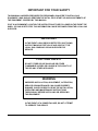
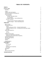
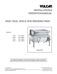
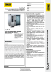
INSTALLATION &
OPERATION MANUAL
GAS & ELECTRIC TILTING BRAISING PANS
MODEL
G30O
G30C
G40O
G40C
E30O
E30C
E40O
E40C
ML -52701
ML-52702
ML-52705
ML-52706
ML-52703
ML-52704
ML-52707
ML-52708
VULCAN-HART COMPANY, P.O. BOX 696, LOUISVILLE, KY 40201-0696, TEL. (502) 778-2791
FORM 30959 (3-96) (Formerly 30763 & 30764)
IMPORTANT FOR YOUR SAFETY
THIS MANUAL HAS BEEN PREPARED FOR PERSONNEL QUALIFIED TO INSTALL GAS
EQUIPMENT, WHO SHOULD PERFORM THE INITIAL FIELD START-UP AND ADJUSTMENTS OF
THE EQUIPMENT COVERED BY THIS MANUAL.
POST IN A PROMINENT LOCATION THE INSTRUCTIONS TO BE FOLLOWED IN THE EVENT THE
SMELL OF GAS IS DETECTED. THIS INFORMATION CAN BE OBTAINED FROM THE LOCAL GAS
SUPPLIER.
IMPORTANT
IN THE EVENT A GAS ODOR IS DETECTED, SHUT DOWN
UNITS AT MAIN SHUTOFF VALVE AND CONTACT THE
LOCAL GAS COMPANY OR GAS SUPPLIER FOR
SERVICE.
FOR YOUR SAFETY
DO NOT STORE OR USE GASOLINE OR OTHER
FLAMMABLE VAPORS OR LIQUIDS IN THE VICINITY OF
THIS OR ANY OTHER APPLIANCE.
WARNING
IMPROPER INSTALLATION, ADJUSTMENT, ALTERATION,
SERVICE OR MAINTENANCE CAN CAUSE PROPERTY
DAMAGE, INJURY OR DEATH. READ THE INSTALLATION,
OPERATING AND MAINTENANCE INSTRUCTIONS
THOROUGHLY BEFORE INSTALLING OR SERVICING
THIS EQUIPMENT.
IN THE EVENT OF A POWER FAILURE, DO NOT ATTEMPT
TO OPERATE THIS DEVICE.
—2—
TABLE OF CONTENTS
GENERAL
4
INSTALLATION
4
Unpacking
Location
Installation Codes and Standards
Leveling and Anchoring Tilting Braising Pan
Service Connections
Gas Connections
Testing the Gas Supply System
Flue Connections
Installation Diagram — Gas Heat Braising Pans
Electrical Connections
Control Circuit Powr Connection (All Braising Pans)
Installation Diagram — Electric Heat Braising Pans
4
5
6
6
7
7
7
7
8
9
9
10
11
OPERATION
Before First Use
Gas Heat Braising Pans
Controls
Lighting and Shutdown of Pilot — Standard Gas Braising Pan
Lighting and Shutdown of Pilot — Gas Braising Pan with Electronic Ignition
Operation
Electric Heat Braising Pans
Controls
Operation
Operation of Lifting System
Braising Pans with Manual Lift (Standard)
Braising Pans with Automatic Power Lift (Optional)
Unloading Prepared Foods
Steaming Inserts (Optional)
Cooking Hints
Cleaning
Cooking Guidelines
11
11
11
11
12
12
13
13
13
14
14
14
15
16
16
17
18
21
MAINTENANCE
Lubrication
Lid Mechanism
Manual Lift
Automatic Power Lift (Optional).
Door Hinges
Adjustments
Vent
Service and Parts Information
21
21
21
21
22
22
22
22
23
TROUBLESHOOTING
-3-
Installation, Operation and Care of TILTING
BRAISING PANS MODELS G300, G400,
G30C, G40C, E300, E400, E30C, & E40C
KEEP THESE INSTRUCTIONS FOR FUTURE USE
GENERAL
Vulcan-Hart Tilting Braising Pans are available in two sizes. Models G30 and E30 have a 30-gallon
capacity and Models G40 and E40 have a 40-gallon capacity. Models with a suffix of "0" have an open
base and models with a suffix of "C" have a closed base.
The tilting braising pan is a versatile piece of equipment. It allows you to stew, simmer, pan fry, braise,
grill or sauté, and all with a very uniform heat pattern.
Standard features on all models include a thermostat, manual timer, manual lift, stationary food pan
support, and 6" legs (2 "bullet" feet and 2 flanged feet).
Optional features include a solid state thermostat, an electric timer, automatic power lift, hinged food pan
support, casters or 6" legs with 4 flanged feet, and swivel faucet. Gas powered models may be ordered
with an optional electronic ignition.
Your Vulcan braising pan is produced with quality workmanship and material. Proper installation, usage
and maintenance will result in many years of satisfactory performance.
Vulcan-Hart Company suggests that you thoroughly read this entire manual and carefully follow all of the
instructions provided.
INSTALLATION
Before installing, verify that the electrical service and gas supply (natural or propane) agree with the
specifications on the rating plate located on the back of one of the front doors.
UNPACKING
This braising pan was carefully inspected before leaving the factory. The Transportation Company
assumes full responsibility for safe delivery upon acceptance of this shipment.
Immediately after unpacking, check for possible shipping damage. If the tilting braising pan is found to be
damaged, save the packaging material and contact the carrier within 15 days of delivery.
-4-
LOCATION
For Gas Powered Braising Pans Only
The braising pan must be kept free and clear of combustible substances. The braising pan, when installed, must
have minimum clearance from combustible and non-combustible construction of 6" from the sides and 6" from the
rear.
The installation location must allow adequate clearances for servicing and proper operation. Recommended
clearances are 24" on the sides and back (for servicing), and 36" on the front. The ceiling should be at least 72"
from the floor.
The braising pan must be installed so that the flow of combustion and ventilation air will not be obstructed. Adequate
clearance for air openings into the combustion chamber must be provided. Make sure there is an adequate supply
of air in the room suitable for the amount of combustion gas feeding the braising pan burners.
Do not permit fans to blow directly at the braising pan. Wherever possible, avoid open windows next to the braising
pan. Avoid wall-type fans which create air cross currents within the room.
Braising Pans Equipped with Casters
If casters are assembled to the braising pan, the installation must be made using a connector (not supplied by
Vulcan) that complies with the Standard for Connectors for Movable Gas Appliances, ANSI-Z21.69 (latest edition),
and a quick-disconnect device that complies with the Standard for Quick-Disconnect Devices for Use With Gas
Fuel, ANSI-Z21.41 (latest edition). Provide a restraining device for the gas line to limit movement of the braising pan
without depending on the connector and/or any quick-disconnect device or its associated piping to limit braising pan
movement. Attach the restraint at the rear of the braising pan (Fig. 1).
If disconnection of the restraint is necessary, turn off the gas supply before disconnection. Reconnect this restraint
prior to turning the gas supply on and returning the braising pan to its originally installed position.
-5-
INSTALLATION CODES AND STANDARDS
Your Vulcan Tilting Braising Pan must be installed in accordance with:
In the United States:
1. State and local codes, or in the absence of local codes, with:
2. National Fuel Gas Code, ANSI-Z223.1 (latest edition), available from the American Gas Association, Inc., 1515
Wilson Blvd., Arlington, VA 22209.
3. National Electrical code ANSI/NFPA-70 (latest edition).
4. ANSI NFPA Standard #96, "Vapor Removal from Cooking Equipment," (latest edition), available from the
National Fire Protection Association, Batterymarch Park, Quincy, MA 02269.
In Canada:
1. Local codes.
2. CAN/CGA-B149.1 Installation for Natural Gas Burning Appliances and Equipment.
3. CAN/CGA-B149.2 Installation for Propane Burning Appliances and Equipment, available from the Canadian Gas
Association, 55 Scarsdale Road, Don Mills, Ontario, Canada M3B2R3.
4. Canadian Electrical Code Part 1 CSA-C22.1 (latest edition).
LEVELING AND ANCHORING TILTING BRAISING PAN
1. Place braising pan in the installation position.
2. Place a carpenter's level on top of the braising pan and turn the adjustable feet to level braising pan table top
side-to-side and front-to-back. Do not attempt to level the braising pan clad plate.
3. Mark hole locations on the floor through the anchoring holes provided in the rear flanged adjustable feet.
4. Remove tilting braising pan from installation position and drill holes in locations marked on the floor. Insert
proper anchoring devices (not supplied).
5. Place tilting braising pan back in the installation position.
6. Place carpenter's level on top of braising pan and re-level side-to-side and front-to-back.
7. Bolt and anchor tilting braising pan securely to the floor.
8. Seal bolts and flanged feet with silastic or equivalent compound.
—6—
SERVICE CONNECTIONS
To reach service and utility connections, remove the left side panel. To remove, hold the panel from
underneath and lift it up. While holding the panel up, swing out the lower part of the panel until it clears
the top flange and remove. If required, the rear panel and inner side panels (open base models only) can
also be removed using the same procedure.
GAS CONNECTIONS (see Fig. 2)
All gas supply connections and any pipe joint compound used must be resistant to the action of propane
gases.
Connect a 1/2" (nominal) gas supply to the braising pan. Recommended incoming gas line pressure is 7"
W.C. (Water Column) for natural gas or 12" W.C. for propane gas. Make sure the pipes are clean and
free of obstructions, dirt, and piping compound.
Codes require that a gas shutoff valve be installed in the gas line ahead of the tilting braising pan.
Natural gas and propane gas braising pans are equipped with fixed orifices and no adjustment is
necessary. The orifices are set at 3.5" W.C. (Water Column) for natural gas, and 10" W.C. for propane
gas.
WARNING: PRIOR TO LIGHTING, CHECK ALL JOINTS IN THE GAS SUPPLY LINE FOR LEAKS. USE
SOAP AND WATER SOLUTION. DO NOT USE AN OPEN FLAME.
After piping has been checked for leaks, all piping receiving gas should be fully purged to remove air.
The electrical control circuit must be connected (see CONTROL CIRCUIT POWER CONNECTION) in
this manual).
Testing the Gas Supply System
When test pressures exceed 1/2 psig (3.45 kPA), the tilting braising pan and its individual shutoff valve
must be disconnected from the gas supply piping system.
When test pressures are 1/2 psig (3.45 kPa) or less, the tilting braising pan must be isolated from the gas
supply system by closing its individual manual shutoff valve.
Flue Connections
DO NOT obstruct the flow of flue gases from the flue duct located on the rear of the tilting braising pan. It
is recommended that the flue gases be ventilated to the outside of the building through a ventilation
system installed by qualified personnel.
From the termination of the braising pan flue vent to the filters of the hood venting system, an 18"
minimum clearance must be maintained.
Information on the construction and installation of ventilating hoods may be obtained from the standard
for "Vapor Removal from Cooking Equipment," NFPA No. 96 (latest edition) available from the National
Fire Protection Association, Batterymarch Park, Quincy, MA 02269.
-7-
INSTALLATION DIAGRAM — GAS HEAT BRAISING PANS
MODEL
NO.
G-30-C
NATURAL GAS
B.T.U./hr.
90,000
PROPANE GAS
B.T.U./hr.
90,000
G-40-C
120,000
120,000
If 9" (229 mm) deep pan (total capacity 30
gallons) is specified on model G-23-C add
2" (51 mm) to dimensions "B", "C". and "D".
LEGEND
1. Electric connection 120 V 1-phase 50/60
DIMENSIONS - INCHES
B
Hz control circuit 300 watts maximum.
Model No.
A
G-30-C
36
39 1/2 11 1/2 66
G-40-C
48
39 1/2 11 1/2 66
C
D
2. Gas connection 1/2" N.P.T.
3. (Optional extra) Hot and cold water
connections if spray hose specified.
(Connections are 1/2" N.P.T.)
DIMENSIONS - MILLIMETERS
—8—
Model No.
A
B
C
D
G-30-C
914
1003
292
1676
G-40-C
121
1003
292
1676
ELECTRICAL CONNECTIONS (see Fig. 3)
WARNING: ELECTRICAL AND GROUNDING CONNECTIONS MUST COMPLY WITH THE NATIONAL
ELECTRICAL CODE AND/OR OTHER LOCAL CODES.
WARNING: DISCONNECT THE ELECTRICAL POWER SUPPLY AND PLACE A TAG AT THE DISCONNECT
SWITCH TO INDICATE THAT YOU ARE WORKING ON THE CIRCUIT.
The control box for field wire connection is located on the lower left side of the braising pan. A knockout hole is
provided for a 1" conduit connection.
1. Remove the control box cover plate. Mount suitable 1" conduit fitting in knockout opening.
2. Connect field wire to the terminal block as indicated on the wiring diagram. The wiring diagram is located on the
inside of the left door on closed base units and on the inside of the center door of open base units. Wire must be
of the type suitable for 75°C service, and of thickness as indicated on marking next to junction box.
3. After making the connections, replace the control box cover plate.
4. The braising pan must be grounded by installing a ground lead, properly grounded, to the ground lug located
inside the junction box.
ELECTRICAL DATA CHART
E30C/0
E40C/0
VOLTS
PHASE
K.W.
AMP
KW.
LX
LY
LZ
208
1
10.2
49
13.6
65
65
—
240
1
13.5
57
18.0
75
75
—
208
3
10.2
29
13.6
43
43
29
240
3
13.5
33
18.0
50
50
33
480
3
13.5
17
18.0
25
25
17
These values are nominal ratings. Field wire connections must be capable of withstanding anticipated surges.
CONTROL CIRCUIT POWER CONNECTION — All braising pans (see Fig's. 2 and 3)
WARNING: APPLIANCES EQUIPPED WITH A FLEXIBLE ELECTRIC SUPPLY CORD ARE PROVIDED WITH A
THREE-PRONG GROUNDING PLUG. IT IS IMPERATIVE THAT THIS PLUG BE CONNECTED INTO A
PROPERLY GROUNDED THREE-PRONG RECEPTACLE, IF THE RECEPTACLE IS NOT THE PROPER
GROUNDING TYPE, CONTACT AN ELECTRICIAN. DO NOT REMOVE THE GROUNDING PRONG FROM THIS
PLUG.
This connection is not required on braising pans equipped with the optional step down transformer.
Connect a 120 volt, 50/60 Hz, 1 phase supply to the pigtail leads in the junction box located on the rear left of the
braising pan. Use copper wire suitable for 5 amperes and 75°C temperature. A ground wire must be connected to
the ground lug in the junction box.
—9—
INSTALLATION DIAGRAM — ELECTRIC HEAT BRAISING PANS
DIMENSIONS - INCHES
B
C
D
LEGEND
1. Electric connection 120 V 1-phase 50/60 Hz control
Model No.
A
E-30-C
36
39 1/2 11 1/2 66
circuit with grounding wire required. (300 wans
E-40-C
48
39 1/2 11 1/2 66
maximum) not required when step down transformer
specified: (Optional extra).
If 9" (229 mm) deep pan (total capacity 30
gallons) is specified on model E-23-C add
2" (51 mm) to dimensions •B". "C". and "D".
2. Electrical power connection 1 3/8" diameter. (1"
conduit)
3. (Optional extra) Hot and cold water connections if
spray hose specified. (Connections are 1/2" N.P.T.)
DIMENSIONS - MILLIMETERS
Model No
-10-
A
B
C
D
E-30-C
914
1003
292
1676
E-40-C
1219
1003
292
1676
OPERATION
WARNING: THE TILTING BRAISING PAN AND ITS PARTS ARE HOT. USE CARE WHEN OPERATING,
CLEANING OR SERVICING THE BRAISING PAN.
BEFORE FIRST USE
Using a non-corrosive, grease-dissolving commercial cleaner, clean the protective metal oils from all surface parts and
the interior of the tilting braising pan. Follow the cleaner manufacturer's directions. Rinse thoroughly and drain the pan.
Wipe dry with a soft clean cloth.
GAS HEAT BRAISING PANS
Controls
Thermostat
— Maintains set temperature by controlling power supply.
On/Off Switch (Red)
— Standard braising pans with thermostatic temperature control — located on a box on
the lower left corner of the braising pan. Braising pans with optional solid state
temperature control — located on a box underneath the table top and behind the left
front door.
Pilot Switch
— (Optional) (Electronic Ignition Only.) When turned to ON, will initiate the electronic
ignition system.
Lighting and Shutdown of Pilot — Standard Gas Braising Pan
Lighting instructions are also located on the back of one of the front doors.
1. Turn main gas supply to the braising pan ON at the shutoff valve.
2. To light the pilot, or to relight the pilot, turn thermostat and knob of combination control valve to OFF.
Wait 5 minutes before relighting.
3. Turn knob of combination control valve to PILOT. Depress this knob and light the pilot using a taper.
Pilot is located behind the hole identified with label "lighter and observation hole." Keep the knob
depressed for about one minute after lighting the pilot.
4. If there is no ignition, or if the pilot does not stay lit, the pilot flame may need to be adjusted. Remove
the cap covering the pilot adjustment screw on the combination control valve. Rotate exposed adjusting
screw counterclockwise one full turn. Then replace cap and repeat steps 1 through 3 above.
5. After pilot is lit, turn the knob of the combination control valve to the ON position.
6. Turn the red On/Off switch to ON. The ON position is indicated by a glowing red light on the switch.
— 11 —
7. Lower the braising pan (see OPERATION OF LIFTING SYSTEM in this manual). The braising pan will not
operate with the pan in the "up" position.
8. Turn the thermostat to the desired cooking temperature.
Complete Shutdown
1. Turn manual shutoff valve to OFF.
2. Turn thermostat and knob of combination control valve to OFF positions. Knob of combination control valve
depresses slightly to turn to the off position.
3. Turn On/Off switch to OFF position.
Lighting and Shutdown of Pilot — Gas Braising Pan with Electronic Ignition
1. If pilot is out, turn pilot switch and thermostat of combination control valve to OFF.
2. Wait 5 minutes before attempting to relight.
3. Turn knob of combination control valve to ON.
4. Move pilot toggle switch to ON.
5. If no ignition, repeat steps 1 through 4 above.
6. If still no ignition, remove pilot adjustment cap from combination control valve and rotate exposed adjusting
screw counterclockwise one full turn. Replace cap and repeat steps 1 through 5 above.
Complete Shutdown
1. Turn pilot switch, thermostat and knob of combination control valve to OFF.
2. Rotate pilot adjusting screw clockwise until pilot goes out.
Operation
The entire flue duct opening, located across the rear of the braising pan, must be left uncovered. If severe lifting of
main burner flames is noted, the ventilator hood may be rated too high (C.F.M.). Contact your ventilator supplier and
have them make the necessary adjustment.
Since all burners are lit from constantly burning pilots, turn the thermostat to the desired temperature to put the
braising pan into operation.
To prevent discoloration of stainless steel cooking surface, do not turn the heat on unless the braising pan is
covered with a fluid, a thin layer of cooking oil, or food to be cooked.
— 12—
DO NOT use the braising pan as a deep fat fryer; use it only for shallow pan frying (cooking oil film not
more than 1/8" thick). Its use for deep-frying could result in a fire hazard. See COOKING HINTS in this
manual for additional information.
Do not overheat the clad stainless steel plate by setting the temperature well above recommended
temperatures, or by operating the braising pan without any fluid inside the pan to absorb heat. Overheating
the plate may cause warpage and will carbonize any cooking oil on the plate and cause sticking.
In case of a power failure, there will be no flames because the combination control valve will shut off the gas
flow. Turn the On/Off switch to OFF. However, the pilot will stay on and the pilot can be left on during the
power failure. When power is restored, it is not necessary to relight the pilot (if it was not turned off); just turn
the On/Off switch to ON and resume cooking.
The lid is counterbalanced and will stay in any position at which it is placed. After some time, the
counterbalancing springs may need to be tightened. Call your local Vulcan-authorized servicer to make
these adjustments.
ELECTRIC HEAT BRAISING PANS
Controls
Thermostat
— Maintains set temperature by controlling power supply.
On/Off Switch (Red)
— Standard braising pans with thermostatic temperature control - located on a box on the
lower left corner of the braising pan. Braising pans with optional solid state temperature
control - located underneath the tabletop and behind the left front door.
Electric Timer Switch
— (Optional) Located underneath the table and behind the left front door. The switch is ON
when the push button is pressed in and stays in.
Operation
Electrically heated braising pans do not require any adjustments before start-up.
Turn the red On/Off switch to ON. The ON position is indicated by a glowing red light on the switch.
Lower the braising pan (see OPERATION OF LIFTING SYSTEM in this manual). The braising pan will not
operate with the pan in the "up" position.
Turn the thermostat to the desired cooking temperature.
To prevent discoloration of stainless steel cooking surface, do not turn the heat on unless the braising pan
surface is covered with a fluid or a thin layer of cooking oil.
DO NOT use the braising pan as a deep fat fryer; use it only for shallow pan frying (cooking oil film not
more than 1/8" thick). Its use for deep-frying could result in a fire hazard. See COOKING HINTS in this
manual for additional information.
— 13—
Do not overheat the clad stainless steel plate by setting the temperature well above recommended temperatures, or
by operating the braising pan without any fluid inside the pan to absorb heat. Overheating the plate may cause
warpage and will carbonize any cooking oil on the plate and cause sticking.
The lid is counterbalanced and will stay in any position at which it is placed. After some time, the counterbalancing
springs may need to be tightened. Call your local Vulcan-authorized servicer to make these adjustments.
OPERATION OF LIFTING SYSTEM
Keep the area underneath and around the braising pan clear of your hands or any other objects when operating the
lifting system.
Do not obstruct any of the moving parts of the lift system located underneath the table top on the right and/or left
side of the braising pan. This area must be kept clear of any objects or obstructions at all times.
Do not operate the lifting system with front doors open (two doors on closed base unit, three doors on open base
unit).
Do not leave the braising pan in the "up" position for extended periods (e.g., overnight or during a shutdown period
between cooking times).
Braising Pans with Manual Lift (Standard)
1. The crank for the manual lift system is located on a hook on the inside of the front door. Open the door and lift
out the crank.
2. Close all front doors.
3. There are two pins on one end of the crank. Insert the crank through the hole on the right door so that the two
pins engage in the slots of the speed reducer coupling located behind the door.
4. Turn the crank handle clockwise to lift the braising pan and counterclockwise to lower the braising pan.
5. This lift system is not affected by power failure and can be operated during a power failure.
6. Refer to the MAINTENANCE section of this manual for lubrication and maintenance instructions.
Braising Pans with Automatic Power Lift (Optional)
The automatic lift cannot raise the braising pan unless the lid is fully opened.
The pan lift is controlled by the white rocker switch located in the hole on the right door.
— 14—
1.
Close all front doors.
2.
Press the upper half of the rocker switch to raise the braising pan and the lower half of the rocker
switch to lower the braising pan. The switch must be held for continuous raising or lowering of the
braising pan.
In case of power failure, the power lift system cannot be operated. Leave the braising pan in whatever
position it is in until the power is restored.
UNLOADING PREPARED FOODS
All braising pans are provided with a stationary support for holding a food receiving pan when unloading
prepared foods.
To install the support, hold the front end with two hands and hook the tabs onto pins in the braising pan
(Fig. 4). The support will accept food receiving pans of 12" x 20" up to 6" deep. Do not use pans greater
than 6" deep.
If your braising pan is equipped with the optional hinged food receiving pan support, the mechanism of the
support system will maintain the top edge of the receiving pan close (approximately 2") to the pouring lip.
To install and use this support, refer to Fig. 4 and follow instructions for installing the standard support
above.
Both types of pan supports can be easily removed when not needed, for example, when cleaning the
braising pan.
— 15—
STEAMING INSERTS (Optional)
Your tilting braising pan can be used for steaming frozen and fresh foods. The 30-gallon pans (Models E
or G30) can be loaded with a maximum of two steaming pans, size 12" x 20" x 4" deep. The 40-gallon
pan (Models E or G40) will accept up to three steam pans of this same size.
To use the braising pan for steaming, fill the pan with 6 to 7 gallons of water (approximately 2" deep) for
30-gallon models, and 8 to 9 gallons of water (approximately 2" deep) for 40-gallon models.
Turn the heat ON. Set the thermostat at 212°F. Allow the water to come to a boil. Then change the
thermostat setting to 250°F and carefully place the steaming inserts into the pan as shown in Fig. 5. Close
the lid and allow steaming for the desired time.
Periodically inspect the water level inside the braising pan. Add water if the water level is less than
1/2"deep.
To use the braising pan as a food warmer or bain marie, follow the same procedure as for steaming, but
increase the depth of the water to allow the bottom and part of the sides of the steaming pans to be
immersed in water. Set the thermostat for the holding or warming temperature desired.
When not in use, the steaming inserts can be stacked for easy storage.
COOKING HINTS
DO NOT use the braising pan for deep fat frying. Restrict frying activity to shallow pan-frying (oil film not
more than 1/8" thick) or sautéing.
A tilting braising pan is quite versatile. It can be used for roasting, simmering, boiling, sautéing, searing,
frying, warming, holding, proofing, thawing, browning, steaming, braising, griddling, or stewing. It can be
used as an oversized skillet, as a bain marie, as a proofing oven, as a stock pot, as a kettle, or as an
even heat range top. It can be used for cooking breakfasts, lunches, and dinners.
Your Vulcan tilting braising pan is a multi-purpose unit that can be used for virtually any type of cooking,
except deep fat frying, with great speed, in large volume, and with considerable savings in labor and
energy.
- 16 -
CLEANING
WARNING: DISCONNECT ELECTRICAL POWER SUPPLY BEFORE CLEANING.
Clean your braising pan regularly. Keep the plate surface clean. To produce evenly cooked, perfectly
braised products, keep pan surface free from carbonized grease. Carbonized grease on the surface
hinders the transfer of heat from the pan surface to the food. This results in spotty browning and loss of
cooking efficiency. Worst of all, carbonized grease tends to cling to the foods, giving them a highly
unsatisfactory and unappetizing appearance.
After Each Use
Clean the pan surface with a wire brush or flexible spatula.
Once A Day
Thoroughly clean the back, sides and front of the pan. Also clean the inside and outside surfaces of the
lid.
Once A Week
Clean the pan surface thoroughly. If necessary, use a griddle stone, wire brush or steel wool on the
surface. Rub with the grain of the metal while still warm. A detergent may be used on the pan surface to
help clean it, but be sure the detergent is thoroughly removed.
Clean other stainless steel surfaces with a damp cloth and polish with a soft dry cloth. To remove
discolorations, use a non-abrasive cleaner. If the braising pan usage is very high, consider going through
the "weekly" cleaning procedures more often than once a week.
When cleaning the braising pan, it is helpful to fill the pan with approximately 10 gallons of warm water
and add detergent. After cleaning, raise the braising pan to drain all water (place a bucket or container
under the pouring lip). Then repeat the procedures for rinsing with clean water.
Burners
Burner air shutter openings must be kept clean.
The main burner and runner burner ports must be kept clean. To clean burners, boil them in a strong
solution of lye water for 15 to 20 minutes. Then either brush with a wire brush or clean gas ports with a
sharp pointed metal instrument to ensure open ports.
— 17—
COOKING GUIDELINES
The guidelines given below are suggested quantities, temperature settings, and estimated numbers of
orders per load and per hour. When two temperatures are given, the first is to start the product, and the
second to finish the product.
The following temperatures should be used:
Temperature
(°F)
Thermostat
Setting
200 Max.
225 - 275
300 - 350
325 - 375
350 - 450
1 -4
5-6
7-8
8-9
9-10
Simmering
Sautéing
Searing
Frying
Grilling
ITEM
PORTION
SIZE
TEMP.
(°F)
BATCHES
PER
HOUR
3 Slices
350
12
1 egg
1 egg
1 egg
I egg
1 1/2 eggs
3 slices
1/2 cup
2 each
225
225
400
225
300-200
450
250
400
5
8
4
5
1
7
2
10
1 pt.
2-3 oz.
4 02.
5 02.
1 -1#
5 02.
400
400
400
450
350
450
10
5
4
3
4
3
G/E300/C PER
LOAD QTY.
PORTIONS
G/E400/C
PER LOAD QTY.
PORTIONS
BREAKFAST FOODS
Bacon
Eggs
-Boiled-Hard
-Boiled-Soft
-Fried
-Poached
-Scrambled
French Toast
Regular Oatmeal
Pancakes
2 Ib.
10
3 Ib.
15
75 eggs
75 eggs
45 eggs
60 eggs
28 gal.
50 slices
40 Ib (200 cups)
50 ea.
75
75
45
60
1100
17
1000
25
20
35
60
60
20
50
15qts.
110-302.
90-4 oz.
90-4 02.
30- 1 Ib.
75-5 02.
30
55
90
90
30
75
2300
150
375
350
575
35 gal.
35 gal.
35 gal.
35 gal.
35 gal.
4500
2250
725
700
1100
50 eggs
50
50 eggs
50
30 eggs
30
36 eggs
36
18 gal.
720
35 slices
12
20 Ib (100 cups) 500
30 ea.
15
FISH
Clams
Fish Cakes
Haddock Fillet
Halibut Steak
Lobster
Swordfish
10qts.
70-3 02.
60-4 02.
60-4 oz.
20 - 1 Ib.
50-5 oz.
SAUCES, GRAVIES, SOUPS
Brown Gravy
Cream Sauce
Cream Soup
French Onion Soup
Meat Sauce
1 02.
202.
6 02.
6 02.
4 02.
350 - 200
250- 175
200
225
350 - 200
2
1
1
1
1
—18—
18 gal.
18 gal. 1
18 gal.
18 gal.
18 gal.
PORTION
SIZE
TEMP.
(°F)
BATCHES
PER
HOUR
CANNED
FRESH
3 oz.
400
6
30 Ib.
125
45 Ib.
200
Beans, Wax, Green
Beets
Broccoli
Cabbage
Carrots
Cauliflower
Corn
Potatoes
Spinach
Turnips
3 oz.
3 oz.
3 oz.
3 oz.
3 oz.
3 oz.
1 Ear
3 oz.
4 oz.
4 oz.
400
400
400
400
400
250
400
400
250
400
3
1
3
5
2
5
8
2
10
2
25 Ib.
30 Ib.
25 Ib.
20 Ib.
35 Ib.
15 Ib.
50 ears
40 Ib.
6 Ib.
20 Ib.
125
125
125
80
150
75
50
200
25
100
50 Ib.
60 Ib.
40 Ib.
30 Ib.
70 Ib.
25 Ib.
75 ears
60 Ib.
9 Ib.
30 Ib.
250
300
200
125
300
125
75
300
35
150
3 oz.
3 oz.
3 oz.
3 oz.
3 oz.
3 oz.
3 oz.
3 oz.
3 oz.
400
250
400
250
250
250
250
400
400
6
4
8
6
3
18
7
10
3
15 Ib.
15 Ib.
12 Ib.
15 Ib.
15 Ib.
15 Ib.
15 Ib.
15 Ib.
15 Ib.
60
60
50
60
50
50
50
75
75
22 1/2 Ib.
22 1/2 Ib.
18 Ib.
22 1/2 Ib.
22 1/2 Ib.
22 1/2 Ib.
22 1/2 Ib.
22 1/2 Ib.
22 1/2 Ib.
90
90
75
90
90
90
90
110
110
ITEM
G/E300/C
PER LOAD
QTY. PORTIONS
G/E400/C
PER LOAD
QTY. PORTIONS
VEGETABLES
FROZEN
Beans, French Green
Lima Beans
Broccoli
Sliced Carrots
Small Whole Carrots
Corn
Small Whole Onions
Peas
Spinach
DESSERTS, PUDDINGS, SWEET SAUCES
Butterscotch Sauce
Cherry Cobbler
Chocolate Sauce
Cornstarch Pudding
Fruit Gelatin
1 oz.
3 oz.
1 oz.
4oz.
3 oz.
200
200
200
200
250
1
1
1
1
2
18 gal.
18 gal.
18 gal.
18 gal.
18 gal.
2300
750
2300
575
750
35 gal.
35 gal.
35 gal.
35 gal.
35 gal.
4500
1500
4500
1100
1500
3 Slices
350
12
2 Ib.
10
3 Ib.
15
6 oz.
8 oz.
5 oz.
3 oz.
3 oz.
1 oz.
2oz.
5 oz.
6 oz.
4 oz.
400 - 225
300
400
300
300
400 - 225
350 - 200
400
400
300 - 200
2
—
5
12
15
3
18 gal.
18 gal.
16 Ib.
7 Ib.
7 Ib.
12 1/2lb.
120 Ib.
16 Ib.
15 Ib.
25 Ib.
350
280
50
35
35
65
500
50
40
110
35 gal.
35 gal.
25 Ib.
10 Ib.
10 Ib.
18 Ib.
180 Ib.
24 Ib.
22 1/2 Ib.
40 Ib.
700
560
75
50
50
100
750
75
60
160
MEAT-POULTRY
Bacon
BEEF
Amer. Chop Suey
Beef Stew
Corned Beef Hash
Cheeseburger
Hamburger
Meatballs
Pot Roast
Salisbury Steak
Sirloin Steak
Swiss Steak
3
5
1
— 19—
PORTION
SIZE
TEMP.
(°F)
BATCHES
PER HOUR
2 - 1/4's
350
3
Whole
FRANKFURTERS
2oz.
350 - 200
Grilled
2oz.
300
Boiled
PORK
2oz.
250
Ham Steak
3 oz.
400
Pork Chops
5 oz.
Sausage Links
TURKEY
ITEM
G/E300/C PER LOAD
QTY. PORTIONS
G/E400/C PER LOAD
QTY. PORTIONS
CHICKEN
Pan Fried
50 pieces
25
80 pieces
40
16-5 Ib.
200
24-5 Ib.
265
8
22 Ib.
176
33 Ib.
264
12
16 Ib.
128
25 Ib.
200
8
10 Ib.
50
15 Ib.
75
350
4
15 Ib.
50
25 Ib.
75
3 links
350
7
30 Ib.
120
45 Ib.
180
Off Carcass
2oz.
400 - 200
—
3 26-30 Ib.
200
4 26-30 Ib.
275
On Carcass
2 oz.
400 - 200
—
4 16-20 Ib.
175
6 16-20 Ib.
265
1 sand.
400
8
35 sand.
35
50 sand.
50
MISCELLANEOUS
Grilled Cheese Sandwich
Macaroni & Cheese
8 oz.
200
2
18 gal.
300
35 gal.
525
Rice
4 oz.
350 - 225
1
20 Ib. raw
320
40 Ib. raw
650
Spaghetti
4 oz.
350 - 225
2
8 Ib. raw
200
12 Ib. raw
300
—20—
MAINTENANCE
WARNING: THE TILTING BRAISING PAN AND ITS PARTS ARE HOT. USE CARE WHEN OPERATING,
CLEANING OR SERVICING THE BRAISING PAN.
WARNING: DISCONNECT ELECTRICAL POWER SUPPLY AND PLACE A TAG AT THE DISCONNECT SWITCH
TO INDICATE THAT YOU ARE WORKING ON THE CIRCUIT BEFORE PERFORMING ANY MAINTENANCE.
LUBRICATION
Lid Mechanism
The lid lift mechanism and tension spring are located behind the shroud (sheet metal panel behind the braising pan)
on both the left and right rear corners of the braising pan.
For smooth operation of the lid, lubricate this mechanism with 8 to 10 drops of lubricating machine oil every 6
months. Place a few drops of oil between the lid arm and stationary block, and a few drops on the shaft around
which the spring is coiled.
Manual Lift
The gear reducer oil must be replaced after one year of operation, and every two years after that.
1. The gear reducer is mounted behind the right door and underneath the table top.
2. Unscrew the drain plug on the bottom of the reducer and drain all oil.
3. Close the drain hole by tightening the drain plug in place.
4. Open the fill plug located on top of the gear reducer.
5. Fill with SAE 40 weight oil of "Gear Lube" quality (approximately 1 pint).
Every 6 months, lubricate the lifting system parts (sprockets, chain, lift arm pivot, etc.) with lubricating machine oil.
Also lubricate the pin where the lift arm is attached to the bottom of the braising pan plate.
The two bearings at the lower end of the lift mechanism are lubricated for life and do not require periodic lubrication.
Automatic Power Lift (Optional)
Lubricate the pin where the lift arm is attached to the bottom of the braising pan plate with lubricating machine oil
every six months.
All other parts of the power lift system are lubricated for life and do not require periodic maintenance.
—21 —
Door Hinges
Lubricate the front door hinges with a silicone spray lubricant every 6 months. Spray the lubricant on the hinge pin at
the top and bottom of all front doors.
ADJUSTMENTS
At least twice a year, have a Vulcan-Hart authorized service person clean and adjust the tilting braising pan for
maximum performance.
VENT
When cool, annually check the ventilation system. Clean the system of any grease build-up or other obstructions
that can affect the flow of the flue gases from the braising pan.
SERVICE AND PARTS INFORMATION
To obtain service and parts information concerning the tilting braising pan, contact the Vulcan-Hart Service Agency
in your area (refer to listing supplied with the braising pan), or Vulcan-Hart Company Service Department at the
address or phone number shown on the front cover of this manual.
—22—
TROUBLESHOOTING
GAS HEAT BRAISING PANS
PROBLEM
Burners do not come on.
POSSIBLE CAUSES
1. Gas supply to braising pan is OFF.
2. Manual gas shutoff valve is OFF.
3. Thermostat is not turned ON.
4. Pan is not in lowest position.
5. Problem with the burners. Contact your Vulcan-Hart
authorized servicer.
Burners produce carbon deposits.
1, Wrong size orifices.
2. Burner air not adjusted properly.
3. Wrong gas supply,
4. Incorrect pressure at supply.
ELECTRIC HEAT BRAISING PANS
PROBLEM
Heating elements do not come on.
POSSIBLE CAUSES
1. Thermostat is not turned ON.
2. Blown fuse in main electrical panel.
3. Pan is not in lowest position.
4. Problem with the heating elements. Contact your
Vulcan-Hart authorized servicer.
FORM 30959 (3-96) (Formerly 30763 & 30764)
— 23 —
PRINTED IN U.S.A.