1
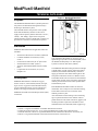
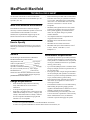
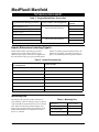
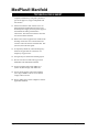
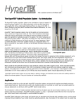
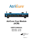
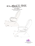
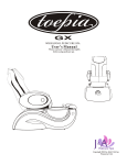
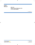
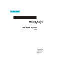
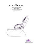
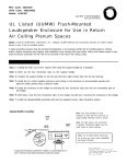
TECHNICAL DATA SHEET MedPlus® Manifold From Hill-Rom Product No. P6804 Series For Parts or Technical Assistance Technical Support: (800) 445-3720 Customer Service: (800) 445-3730 Canada: (800) 267-2337 International: Contact your distributor. www.hill-rom.com tds040 MedPlus® Manifold Technical Data Sheet Revisions Revision Letter Pages Affected Original Issue Date January, 2001 tds040 January 16, 2001 tds040 Page i Revisions 2001 by Hill-Rom Services, Inc. ALL RIGHTS RESERVED. No part of this text shall be reproduced or transmitted in any form or by any means, electronic or mechanical, including photocopying, recording, or by any information or retrieval system without written permission from Hill-Rom Services, Inc. (Hill-Rom). First Edition First Printing 2001 Printed in the USA Hill-Rom® is a registered trademark of Hill-Rom Services, Inc. MedPlus® is a registered trademark of Hill-Rom Medaes, Inc. National Electrical Code® is a registered trademark of National Fire Protection Association, Inc. NEC® is a registered trademark of National Fire Protection Association, Inc. Underwriters Laboratories Inc.® is a registered trademark of Underwriters Laboratories Inc. The information contained in this document is subject to change without notice. Hill-Rom makes no commitment to update or keep current, the information contained in this document. The only product warranty intended by Hill-Rom is the express, written warranty accompanying the bill of sale to the original purchaser. Hill-Rom makes no other warranty, express or implied, and in particular, makes no warranty of merchantability or fitness for a particular purpose. Additional copies of this technical data sheet can be obtained from Hill-Rom. Page ii tds040 January 16, 2001 Table of Contents Purpose . . . . . . . . . . . . . . . . . . . . . . . . . . . . . . . . . . . . . . . . . . . . . . . . . . . . . . . . . . . . . 1 Standards. . . . . . . . . . . . . . . . . . . . . . . . . . . . . . . . . . . . . . . . . . . . . . . . . . . . . . . . . . . . 1 Description . . . . . . . . . . . . . . . . . . . . . . . . . . . . . . . . . . . . . . . . . . . . . . . . . . . . . . . . . . 1 MedPlus® Manifold Accessories . . . . . . . . . . . . . . . . . . . . . . . . . . . . . . . . . . . . . . . . . 2 How to Specify . . . . . . . . . . . . . . . . . . . . . . . . . . . . . . . . . . . . . . . . . . . . . . . . . . . . . . . 2 General . . . . . . . . . . . . . . . . . . . . . . . . . . . . . . . . . . . . . . . . . . . . . . . . . . . . . . . . . . . . . 2 Design Requirements . . . . . . . . . . . . . . . . . . . . . . . . . . . . . . . . . . . . . . . . . . . . . . . . . . 2 Performance Requirements. . . . . . . . . . . . . . . . . . . . . . . . . . . . . . . . . . . . . . . . . . . . . . 2 Components per Manifold . . . . . . . . . . . . . . . . . . . . . . . . . . . . . . . . . . . . . . . . . . . . . . 3 Electrical System . . . . . . . . . . . . . . . . . . . . . . . . . . . . . . . . . . . . . . . . . . . . . . . . . . . . . 3 Installation System Check . . . . . . . . . . . . . . . . . . . . . . . . . . . . . . . . . . . . . . . . . . . . . . 3 Service . . . . . . . . . . . . . . . . . . . . . . . . . . . . . . . . . . . . . . . . . . . . . . . . . . . . . . . . . . . . . 3 Submittals . . . . . . . . . . . . . . . . . . . . . . . . . . . . . . . . . . . . . . . . . . . . . . . . . . . . . . . . . . . 3 Warranty . . . . . . . . . . . . . . . . . . . . . . . . . . . . . . . . . . . . . . . . . . . . . . . . . . . . . . . . . . . . 3 Dimensions and Flow . . . . . . . . . . . . . . . . . . . . . . . . . . . . . . . . . . . . . . . . . . . . . . . . . . 3 Flow Capacity . . . . . . . . . . . . . . . . . . . . . . . . . . . . . . . . . . . . . . . . . . . . . . . . . . . . . . . . 4 Ordering Information . . . . . . . . . . . . . . . . . . . . . . . . . . . . . . . . . . . . . . . . . . . . . . . . . . 5 Header Extensions Including Pigtails . . . . . . . . . . . . . . . . . . . . . . . . . . . . . . . . . . . . . . 6 Mounting Kits . . . . . . . . . . . . . . . . . . . . . . . . . . . . . . . . . . . . . . . . . . . . . . . . . . . . . . . . 6 Installation Information . . . . . . . . . . . . . . . . . . . . . . . . . . . . . . . . . . . . . . . . . . . . . . . . 7 January 16, 2001 tds040 Page iii Table of Contents NOTES: Page iv tds040 January 16, 2001 MedPlus® Manifold TECHNICAL DATA SHEET Figure 1. MedPlus® Manifold Purpose The MedPlus® Manifold reduces cylinder pressure to line pressure for distribution through the facility’s medical gas distribution system. The manifold monitors the pressure of the cylinder banks and automatically switches to the reserve supply when the primary bank is exhausted. “In Use”, “Ready”, and “Empty” lights on the front panel indicate the status of each cylinder bank. Contacts are provided for connection to external alarm systems. Standards MedPlus® Manifolds meet all applicable codes and standards: t040_001 • • • • • • National Fire Protection Association (NFPA) 99 Canadian Standards Association (CSA® ) Z-305.1 Underwriters Laboratories Inc.® Section 407 National Electrical Code® (NEC® ) American National Standards Institute (ANSI) B57.1 Compressed Gas Association, Inc. (CGA) Pamphlet V-1 NOTE: 1 This manifold is not suitable for liquid oxygen or liquid nitrogen cylinders. For those manifolds, refer to the MedPlus® Manifold for Use With Liquid Cylinders Technical Data Sheet (tds038). 2 3 4 The MedPlus® Manifold is designed for left and right cylinder banks of equal capacity. When one bank is exhausted, the manifold automatically switches to supply gas from the other bank. Status lights on the front panel indicate the switch-over. Remote visual and audible alarms can be connected to the manifold circuit board. Gauges on the front panel continuously indicate pressures within both of the cylinder banks and the delivery lines. Description MedPlus® Manifolds are available for oxygen, nitrous oxide, air, carbon dioxide, helium, nitrogen, argon, xenon, oxygen and carbon dioxide mixture, oxygen and helium mixture, oxygen and nitrogen mixture, and oxygen and nitrous oxide mixture. MedPlus® manifolds use National Pipe Thread (NPT) connections. Each MedPlus® Manifold includes an electrical transformer with a utility box for external mounting, and an NPT-to-tube union for connection to the medical gas delivery line. Also included are wall-mounting or floor-mounting legs as specified and the correct number of blind glands and union nuts, header extensions, pigtails, and mounting brackets required for installation. If the manifold will be floor-mounted, header support legs 1. CSA® is a registered trademark of Canadian Standards Association. 2. Underwriters Laboratories Inc. ® is a registered trademark of Underwriters Laboratories Inc. 3. National Electrical Code® is a registered trademark of the National Fire Protection Association, Inc. 4. NEC® is a registered trademark of the National Fire Protection Association, Inc. January 16, 2001 tds040 Page 1 of 8 MedPlus® Manifold TECHNICAL DATA SHEET • for the header extensions are also included. With accessories, the manifold can accommodate up to 28 cylinders (14 x 14). MedPlus® Manifold Accessories Each Header Extension Kit contains all the parts necessary to add two additional cylinders to each side of the manifold. If the manifold is to be floormounted, the required header support legs for the header extensions must be ordered separately. • • • • How to Specify • • Include the following information in your order for medical gas manifolds. See “Ordering Information” on page 5. Each manifold is provided with an intermediate and a line relief valve pre-joined for connection to a vent line. Manifolds with no intermediate relief valve or an intermediate relief valve that cannot be connected to a vent line are not acceptable. Manifolds, blind gland and union nuts, header extensions, and pigtails are CGA gas-specific. Each cylinder pigtail is provided with a nonreturn valve to permit change of cylinders without shutdown. All component material is compatible with oxygen and nitrous oxide. Manifolds can be wall-mounted or floormounted. Manifolds are UL-listed, Section 407. Manifolds will meet current NFPA 99, CSA® Z-305.1, NEC® , ANSI B57.1, CGA Pamphlet V-1. 1 2 General Performance Requirements The medical gas manifold shall be a Hill-Rom MedPlus® Manifold, product number ____________, designed for use with ____________ (type of gas), with two equal banks of ____________ (quantity) cylinders for a total of ____________ (quantity) cylinders, and shall not exceed __________ in length, 24" (0.6 m) in width, and 66" (1.7m) in height. Manifold shall be ____________ (wall or floor) mounted. If floor-mounted, manifold will include __________ (quantity) Header Support Leg Kit(s) product number P6804-9040-031. • • • • Design Requirements • • • Each manifold is fully encased in a housing easily removable for service access and installation. A line pressure gauge is provided. Each bank is provided with a contents gauge and LED indicator lamps for “In Use,” “Empty,” and “Ready.” Manifolds without a “Ready” indicator are not acceptable. Manifolds using light bulb indicators are not acceptable. • • The capacity of each 55 psi (379 kPa) manifold (all gases besides nitrogen) is 30 cfm (850 lpm) with cylinders at a standard switch-over pressure of 150 psi (1034 kPa) and with a 10 psi (69kPa) delivery pressure drop. Up to 90 cfm (2549 lpm) flow is available with a 250 psi (1724 lpm) switch-over pressure and a 15 psi (103 kPa) drop. The capacity of each 180 psi nitrogen manifold is 70 cfm (1982 lpm) with cylinders at a standard switch-over pressure of 300 psi (2068 kPa) with a 15 psi (103 kPa) delivery pressure drop. Each manifold is fully automatic and requires no intervention by an operator to switch over to reserve power bank. The manifold switches over to the other bank by dome loading the operating supply pressure regulator. Manifolds that use shuttle valves or are manually switched are not acceptable. The manifold design is intrinsically safe in the event of electrical or pneumatic control circuitry failure. Should failure occur, the manifold continues to operate and supply the system. 1. CSA® is a registered trademark of Canadian Standards Association. 2. NEC® is a registered trademark of National Fire Protection Association, Inc. Page 2 of 8 tds040 January 16, 2001 MedPlus® Manifold TECHNICAL DATA SHEET Components per Manifold Installation System Check • Relief valves that exceed the maximum regulator flow capacity with reset pressure greater than the normal operating pressure of the line they protect • Full enclosure that is removable for service without the use of tools. The enclosure is lockable (lock provided by others). Red “Empty,” green “Ready,” and amber “In Use” LED indicators for indicating switch-over from primary to secondary supply and bank status Dry electrical contacts for connection to master alarms Left and right bank pressure gauges Central delivery line capacity gauge for continuous indication Bank regulators and dome regulator Full duplex delivery line regulators with four isolation check valves and intermediate pressure service bypass Soft-seat, hand-tight pigtails and check valves • • • • • • • After installation, Hill-Rom offers an optional system check to certify that there are no cross-connections. Hill-Rom certification, in accordance with NFPA 99, helps to ensure that the medical gas system operates safely and protects the patient. Service Service will be provided by a Hill-Rom-approved service organization. Third party service is not acceptable. Submittals Hill-Rom will submit documentation detailing specified design and performance requirements, including delivery pressure and flow capabilities. Warranty Please refer to the service manual for the warranty. Electrical System A step-down transformer is provided with each manifold for installation inside the manifold cabinet or at a remote location. The transformer requires connection to a 120 V AC Essential Electrical Distribution power and delivers 24 V AC to manifold circuit board where it is converted to V DC to power the solenoid, relays, LEDs, and switches. Dimensions and Flow Both wall-mounted and floor-mounted manifolds are 24" (61 cm) in width and 66" (168 cm) in height. See table 1 for cylinder lengths. Lengths of wall-mounted or floor-mounted manifolds vary with the number of cylinders attached. The maximum recommended number of cylinders for the MedPlus® Manifold is 28 (14 on each side). For MedPlus® Manifold dimensions, see figure 2 on page 4. Table 1. Cylinder Lengths January 16, 2001 Number of Cylinders Length 4 (2 x 2) 8 (4 x 4) 12 (6 x 6) 16 (8 x 8) 20 (10 x 10) 24 (12 x 12) 28 (14 x 14) 2' 7" (0.8 m) 4' 10" (1.5 m) 6' 10" (2.1 m) 8' 10" (2.7 m) 10' 10" (3.3 m) 12' 10" (3.9 m) 14' 10" (4.5 m) tds040 Page 3 of 8 MedPlus® Manifold TECHNICAL DATA SHEET Flow Capacity dioxide, helium, argon, xenon, and gas mixture manifolds. There is a 15 psi delivery drop from a 180 psi static pressure for nitrogen manifolds. The table 2 on page 4 shows the flow capacity for various switch-over pressures when there is a 5 psi (35 kPa), 10 psi (69 kPa), or 15 psi (103 kPa) delivery pressure drop from the 55 psi (379 kPa) static pressure for oxygen, nitrous oxide, air, carbon Nitrogen manifolds with line pressures up to 250 psi (1724 kPa) are also available. Call Hill-Rom Customer Support at (800) 445-3730 for information. Table 2. Delivery Pressure Drop Switch-over Pressure Delivery Pressure Drop for All Gases Except Nitrogen 55 psi (379 kPa) 5 psi (35 kPa) 10 psi (69 kPa) 15 psi (103 kPa) 100 psi (690 kPa) 7 cfm (198 lpm) 20 cfm (566 lpm) 30 cfm (850 lpm) 150 psi (1034 kPa) 10 cfm (283 lpm) 30 cfm (850 lpm) 50 cfm (1416 lpm) 200 psi (1379 kPa) 30 cfm (850 lpm) 55 cfm (1557 lpm) 75 cfm (2114 lpm) 250 psi (1724 kPa) 40 cfm (1133 lpm) 70 cfm (1982 lpm) 90 cfm (2549 lpm) 300 psi (2068 kPa) N/A N/A N/A NOTE: The 180 psi (1241 ka) nitrogen manifold with of a delivery drop of 15 psi (103 kPa) has a flow of 70 cfm (1982 lpm), and a switch-over pressure of 300 psi (2069 kPa). Figure 2. Dimensions Page 4 of 8 tds040 January 16, 2001 MedPlus® Manifold TECHNICAL DATA SHEET Full cylinders of compressed gas, except nitrous oxide and carbon dioxide, normally contain approximately 2200 psi (15169 kPa). Nitrous oxide and carbon dioxide are liquefied in standard full cylinders and cylinder pressures vary with temperatures (see figure 3 on page 5). Figure 3. .Vapor Pressure versus Temperature for Nitrous Oxide and Carbon Dioxide Cylinders Ordering Information Table 3. Gas Types Type of Gas H - Size cfh (lph) G - Size cfm (lph) Product Number (CGA Designation) Oxygen 251 (7100) 187 (5300) P6804-9040-009 (CGA 540) Nitrous Oxide 558 (15800) 489 (13800) P6804-9040-010 (CGA 326) Air 234 (6620) 179 (5070) P6804-9040-012 (CGA 346) Carbon Dioxide 558 (15800) 436 (12300) P6804-9040-013 (CGA 320) Helium 219 (6200) 141 (4000) P6804-9040-014 (CGA 580) Argon 244 (6909) 187 (5300) Indicate Gas When Ordering Xenon 89 (2520) -- Indicate Gas When Ordering Nitrogen 230 (6500) -- P6804-9040-011 (CGA 580) January 16, 2001 tds040 Total Number of Cylinders Page 5 of 8 MedPlus® Manifold TECHNICAL DATA SHEET Table 4. Oxygen Mixed With a Second Gas Oxygen Plus the Following Second Gas: Product Number (CGA Designation) Total Number of Cylinders P6804-9040-015 (CGA 280) Specify Gas When Ordering Carbon Dioxide <7.5% Helium <80.5% Nitrogen <76.5% Nitrous Oxide 47.5% to 53.5% P6804-9040-016 (CGA 500) Specify Gas When Ordering Carbon Dioxide >7.5% Helium >80.5% Header Extensions Including Pigtails Header Extension Kits (including gas-specific pigtails) have product numbers specific to the different types of gases. These kits are shipped with the order based on the type of gas specified and the number of cylinders specified. Each kit allows the addition of 4 cylinders, 2 per bank. See table 5 on page 6, for Header Extension Kit product numbers. Table 5. Header Extension Kits Type of Gas (CGA Designation) Product Number Oxygen (CGA 540) P6804-9040-023 Nitrous Oxide (CGA326) P6804-9040-024 Air (CGA 346) P6804-9040-026 Carbon Dioxide (CGA 320) P6804-9040-027 Helium (CGA580) P6804-9040-025 Argon (CGA580) P6804-9040-025 Xenon (CGA 580) P6804-9040-025 Nitrogen (CGA 580) P6804-9040-025 Mounting Kits Mounting kits have specific product numbers for wall-mounting or floor-mounting, see table 6. Specify if the manifold will be mounted to the wall or onto the floor. When floor mounting, Header Support Leg Kit(s) must be specified in the same quantities as for Header Extension Kits for configurations of more than 2 x 2 cylinders. Page 6 of 8 Table 6. Mounting Kits Description Product Number Wall Mounting Kit P6804-9040-022 Floor Mounting Kit P6804-9040-030 Header Support Leg Kit P6804-9040-031 tds040 January 16, 2001 MedPlus® Manifold TECHNICAL DATA SHEET Table 7. MedPlus® Manifold Configuration Chart Cylinders Number of Header Extension Kits Required 2x2 0 4x4 1 6x6 2 8x8 3 10 x 10 4 12 x 12 5 14 x 14 6 Installation Information Installation instructions are included in the manual shipped with each manifold. When planning installation, note the following additional information: 1. The manifold room must not be used for any purpose other than the manifold and cylinder storage. The manifold room door must be lockable. Provide 3 sets of keys. 5. Allow sufficient space to manage the cylinders and the manifold, and to store empty and reserve cylinders. 6. The manifold room must constructed out of at least 1 hour fire-rated material, and all interior finishes must be noncombustible. 7. The manifold room must meet NFPA 99 and the National Electrical Code® standards for ordinary locations. The manifold room must meet any local electrical code requirements. All electrical fixtures, including receptacles, must be in fixed locations at least 60 "(152 cm) above the finished floor. 2. Locate the manifold and cylinders in a vented room on the ground floor, by an exterior wall with easy access to the loading dock. If manifolds are placed out of doors, they should be covered to prevent exposure to direct sunlight and rain. 3. Provide dedicated mechanical venting or natural venting through an opening of at least 72 sq in (0.05 sq m) total free area. Venting must be to the outside of the building and not into a major egress corridor. If vents are open to corridors, they must be provided with a fire damper. Avoid locations near high temperatures, such as boiler rooms. 8. Provide chains or cables to restrain cylinders, including empty and reserve cylinders. 9. Do not locate manifolds in the same room with medical air or medical vacuum plants. According to NFPA 99, the temperature of the manifold room should not go below 32°F (0°C) or above 100°F (38°C). The temperature of the cylinders should never exceed 130°F (54°C). The heating in the manifold room must be steam, hot water, or other indirect means. Do not use electric heaters, gas heaters, etc., which have open flames or may be explosion hazards. 11. Each pigtail must be connected to a cylinder to prevent gas leaks. If there is a pigtail with no cylinder, remove the pigtail from the header and seal the header inlet securely with a gas-specific blind gland and nut. 4. January 16, 2001 10. Do not repeatedly bend, sharply bend, or twist the pigtail’s copper tubing. 12. Install the manifold according to Hill-Rom’s instructions. Test the manifold for leaks after tds040 Page 7 of 8 MedPlus® Manifold TECHNICAL DATA SHEET complete installation by using full cylinders of gas and an approved, oxygen-compatible leak test solution. 13. Electrical contractor must connect 120 V AC Essential Electrical Distribution power to the manifold power supply and wire power supply to the manifold according to Hill-Rom’s instructions. The electrical contractor must also wire and test alarm functions. 14. Relief valves must be piped to the outside of the building. Ensure the vent is turned down and screened. The vent must be located at least 120" (305 cm) above the final grade. 15. If required by NFPA 99, install an Emergency Pressure Oxygen Inlet for connection of a temporary oxygen source. 16. Nitrogen may be stored with oxidizing agents. 17. Do not store nitrous oxide and oxygen with flammable and combustible materials. 18. Oxygen supplies greater than 20000 cu ft (566 cu m) must comply with NFPA 99. 19. Nitrous oxide supplies greater than 3200 lbs (1451 kg) or 28000 cu ft (793 cu m) should comply with CGA G8.1. 20. Review NFPA 99 to ensure compliance with all applicable standards. Page 8 of 8 tds040 January 16, 2001