1
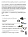
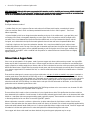
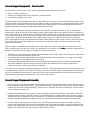
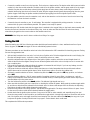
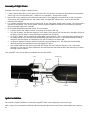
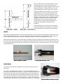
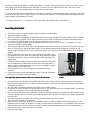
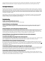
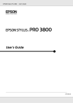
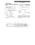
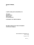
The HyperTEK
HyperTEK® Hybrid Propulsion System – An Introduction
The HyperTEK® hybrid propulsion system is the culmination of years of research in
hybrid propulsion systems. It is a direct descendent of the very first HPR hybrid
and possibly first nitrous oxide based hybrid ever flown on August 16, 1994 in
Miami, Florida by the group which founded Environmental Aeroscience, Inc. with
Korey Kline, TRA # 009.
HyperTEK® hybrid propulsion systems may be the safest and most economical
way to power your high-power rocket yet. One of the tremendous advantages
offered by nitrous oxide hybrids is the safety of both the oxidizer and the fuel
grain. No pyrotechnic materials are used in this system. The motor hardware and
fuel grains (including HyEFX™ fuel grains) are totally inert. Only when the nitrous
oxide tank is filled remotely on the launch pad and the proper sequence of startup events take place is the motor capable of acting as a propulsive device. If a
launch is aborted for any reason, the tank can be dumped remotely rendering the
system safe.
HyperTEK® hybrid motors are a “classic” hybrid configuration using a liquid
oxidizer (nitrous oxide) and a solid fuel (a thermoplastic polymer). The nitrous
oxide is a self-pressurizing condensed gas, which is stored within the oxidizer
A few HyperTEK
HyperTEK®® systems
tank. The behavior and handling of nitrous oxide is very similar to carbon dioxide.
Under normal atmospheric conditions, the nitrous oxide is self-pressurized to
between 650 and 750 pounds per square inch (psi), which allows the motor to operate at initial chamber pressures of up to
about 550 psi. As liquid nitrous oxide is delivered during motor burn (liquid phase), the tank temperature drops due to
evaporative cooling, and the chamber pressure drops correspondingly giving the motor a regressive thrust profile, which is
ideal for nearly all applications. Once the liquid nitrous oxide is depleted, the remaining pressurized gas is delivered to the
combustion chamber as the motor burns for another few seconds at a reduced thrust level (blow-down phase).
Nitrous oxide has the chemical formula N2 0. Each molecule contains about 36% oxygen by mass, which compares favorably
with ammonium perchlorate at about 34%. With the remainder nitrogen, having fairly low molecular weight and being
gaseous, the performance of nitrous oxide and hydrocarbon fuels is reasonable. As an example, under standard conditions a
combination of 87% nitrous oxide and 13% HTPB by mass has a theoretical specific impulse approaching 260 seconds.
HyperTEK® hybrid rocket motors do not have delay or ejection charges, and therefore must be used with auxiliary devices to
deploy the recovery system. Many such devices are commercially available.
Application
Many existing rocket kits can be used with HyperTEK® propulsion systems, and popular kit suppliers are already producing
hybrid-ready rocket kits. Nearly any HPR rocket with suitable provision for mounting the motor, plus an auxiliary system for
recovery deployment can be flown with HyperTEK® hybrid rocket motors.
The introduction in 2001 of industry-standard diameter tanks for all systems plus the use of bottom venting in the L and M
systems means that converting to HyperTEK® hybrid propulsion is a snap. It generally involves little more than ensuring that
your motor mount tube is long enough to accommodate the system.
HyperTEK® flight hardware is often longer and heavier than the equivalent total-impulse solid propellant motor, and the center
of gravity (CG) and stability of your rocket should be carefully examined. Also, the location of the oxidizer tank, the weight loss
during motor burn and the rearward location of the oxidizer mass during acceleration may cause a progressively rearward CG
shift. Ensure that your rocket is stable with the flight hardware at burnout weight and loaded weight before committing to
flight.
It is important to be able to see the liquid venting in order to know when to stop filling and launch. When using the
HyperTEK® “J” systems, the oxidizer tank must be vented through the side of the airframe as equal diameter of the tank and
fuel grain does not allow bottom venting. Usually a small hole drilled in the motor mount and/or airframe tube and aligned
with the vent is sufficient for smaller diameter rockets, e.g. minimum diameter up to 3” diameter. For larger diameter rockets,
a small piece of flexible tubing should be inserted from the outside of the airframe and pushed over the vent fitting, and
trimmed just long enough to vent to the outside of the vehicle. The other option is to use a removable motor mount, and run
the flexible vent tube through a small hole, down along the outside of the motor mount tube and out the rear of the rocket.
HyperTEK® hybrid rocket motors have no time delay or ejection charge. A timer, altimeter or other such device must be used
to activate the recovery system. Be aware that if an altimeter is used, it must be sealed from the motor section in its own
properly vented chamber so that any accidental pressurization in the motor section (from nitrous oxide venting) does not
affect barometric sensor readings and cause ejection problems.
Like all types of motor systems, a positive means of motor retention must be used both for safety and to protect your
hardware investment. Ensure that your motor retention method is capable of retaining the weight of the motor system under
the stresses of recovery deployment. The new 75mm and 98mm systems offer an optional larger-diameter retaining ring as
part of the rear adapter, that can be fastened to your model’s rear centering ring with four machine screws for positive
retention.
Ground Support Equipment
The ground support equipment consists of the following components:
•
Launch Stem; a coaxial tube with adjustable mount that fits to the launch rod or rail
and has male 4AN fittings for the gaseous oxygen and nitrous oxide lines.
•
Gaseous oxygen (GOX) line; a 10-foot stainless steel-braided hose with
red female 4AN fittings.
Nitrous oxide line; a 10-foot stainless steel-braided hose with blue
female 4AN fittings.
•
•
Nitrous oxide Solenoid Assembly; consisting of fill solenoid, dump solenoid, blue male 4AN
fitting, and CGA 326 tank fittings for industrial nitrous oxide tanks. CGA 660 tank valve
fittings for hot rod nitrous oxide tanks are an available option.
•
GOX Assembly; consisting of an oxygen regulator, CGA 540 tank fitting,
solenoid valve, check valve and a red female 4AN fitting.
•
Ignition module; 7500VDC output generates an arc across the ignition wire for ignition of the fuel
grain. Fuse-protected, comes with spare fuses.
•
Launch Controller; equipped with Safe & Arm key switch, LED power indicator, threeposition rotary switch for Fill/Dump/Fire functions, and momentary toggle actuator
switch. Reverse polarity protected.
•
Satellite Control Box with color-coded sockets; two outlets for the nitrous oxide fill and
dump solenoids, plus outlets for the GOX solenoid and ignition module.
•
100 foot 3-prong extension cord for connecting the launch controller and satellite control box.
•
One roll of 24 gauge 2-conductor ignitor wire.
VERY IMPORTANT:
IMPORTANT: Although this system uses standard AC extension cords for durability and economy, NEVER CONNECT ANY
CORD OR COMPONENT OF YOUR HyperTEK
HyperTEK®® SYSTEM TO ANY POWER SOURCE OTHER THAN 12 VOLTS DC AS INSTRUCTED.
TO DO SO IS HAZARDOUS AND WILL RESULT IN PERMANENT DAMAGE TO THE SYSTEM!
Flight Hardware
The Flight Hardware consists of:
• Oxidizer Tank; the J and L systems offer two tank volumes for different total impulse, currently the M system
offers one tank size. New in 2001 are industry standard diameter tanks for the L and M systems – 75mm and
98mm respectively.
• Injector End Bell; which has an integral vent tube extending to the top of the oxidizer tank, a gas vent fitting, and
a metering orifice (fixed or changeable depending on motor type). Three o-ring seals are used in the flight motor,
one which forms a seal between the injector bell and the oxidizer tank; one or two between the injector and the
fuel grain; and a third within the injector that seals against the launch stem and forms the patented Kline valve.
• Fuel Grain; single-use, also forms the combustion chamber. It is a one-piece molded fuel grain, with an insertmolded silica-phenolic nozzle. The top of the fuel grain is threaded and screws into the injector bell. Fuel grains are
included with your motor system, and are available separately as well. Fuel grains come in two types; standard with
unmodified fuel, and HyEFX™ with a modified fuel composition for enhanced flame and smoke effects and slightly
higher performance.
Nitrous Oxide & Oxygen Tanks
Prior to set up and operation of the system, tanks of gaseous oxygen and nitrous oxide must be procured. Your HyperTEK®
dealer may be able to recommend a local source. Gaseous oxygen and nitrous oxide can be obtained at most industrial gas
supply companies or welding supply shops. Nitrous oxide can also be obtained at some hot rod shops under the NOS Systems
Nitrous Plus brand name. Oxygen tanks are normally colored green, and nitrous oxide tanks are normally blue. The valve fitting
on a gaseous oxygen bottle is a standard CGA 540, on a nitrous oxide bottle either CGA326 for industrial tanks or CGA 660
for hot rod.
There are three valve types in common use on nitrous oxide tanks, only two of which are usable in our system. Anesthetic or
medical grade nitrous oxide SHOULD NOT BE USED as this is a controlled substance and possession of this material without
proper documentation could violate federal laws. These tanks are also supplied with a valve that has a limited flow rate and is
unable to adequately supply the liquid nitrous oxide to fill the tank. Medical grade tanks are supplied with chrome plated
valves that mate with CGA 326 fittings. Use either the hot rod style CGA 660 valve used on NOS tanks, or the CGA 326-AA
grade valve used on industrial grade nitrous oxide.
The nitrous oxide solenoid assembly is supplied with CGA 326 fittings as these are in more common use, however CGA 660
fittings are available from your HyperTEK® dealer if required.
The term Nitrous Plus is used to refer to automotive or hot rod grade nitrous oxide. This signifies that the nitrous oxide has
been denatured by the addition of small amounts of sulfur dioxide. Industrial grade nitrous oxide can be denatured with sulfur
dioxide or a mercaptan (the same pungent smelling agent used with propane). These materials are added to the nitrous oxide
to discourage abuse, but do not affect it’s use with HyperTEK® systems.
Nitrous oxide tanks come with or without a siphon tube. A siphon tube allows the liquid nitrous oxide to flow from the
bottom of the tank rather than the gaseous nitrous oxide from the top of the tank. Hot rod tanks are typically supplied with a
siphon tube while industrial tanks usually are not. If a nitrous oxide tank without a siphon tube is used, a stand or support will
be needed to hold the tank upside down in order that liquid will be delivered through the tank valve.
Once oxygen and nitrous oxide tanks have been obtained, the ground support equipment may be set up.
Ground Support Equipment – how it works:
The GSE performs three functions, each of which is controlled remotely via the launch controller:
•
•
•
filling of the flight oxidizer tank
dumping of the flight oxidizer tank in the event of an aborted launch
non-pyrotechnic ignition of the motor
The flight oxidizer tank is filled through the central coaxial tube in the launch stem. This tube mates and seals with the o-ring
in the injector bell, forming the Kline valve. After the rocket is placed on the launch stem, it is restrained with tie-straps placed
through the slots in the bottom of the motor and affixed to the fill stem assembly. The tie-straps prevent the fill tube from
ejecting from the Kline valve when the tank is pressurized with nitrous oxide.
The fill solenoid is activated by setting the mode selector rotary switch on the launch controller to “Fill” and pressing the
activate switch. This opens the nitrous oxide solenoid, allowing liquid nitrous oxide to flow through the hose, through the fill
tube on the launch stem, through the Kline valve and then into the oxidizer tank. The oxidizer tank has a vent tube which runs
from the top of the tank to a port on the side of the injector bell, and from which nitrous oxide is vented to the exterior of the
rocket airframe. During filling, only gaseous nitrous oxide is vented, which is not visible. When the tank is full and liquid
nitrous oxide begins to vent, the vent plume becomes visible indicating that the rocket is ready to launch. This will take about
25 to 30 seconds for the smaller J systems up to 2 minutes for the larger (M) systems. At this point the activation toggle
switch should be released.
When the oxidizer tank is filled and the venting nitrous oxide is visible, the rocket is ready to fire. The rotary switch on the
launch controller is placed on the “Fire” position, the countdown may commence, and at ZERO the activation toggle switch is
pushed and held. When the fire sequence is initiated, the following events occur:
•
•
•
•
The ignition module and the oxygen solenoid are simultaneously activated. High voltage from the ignition module creates
an arc across the exposed ends of the ignition wire.
A few milliseconds later the oxygen reaches the combustion chamber, and in the presence of the oxygen, the insulation
on the wire begins to burns rapidly, igniting the fuel grain.
The fuel grain begins burning with the GOX, burning through the tie-strap that retains the fill stem in the Kline valve.
The tie-strap releases the fill stem, which pops free of the Kline valve releasing the flow of nitrous oxide into the
combustion chamber, and the rocket launches immediately.
If the launch must be aborted or substantially delayed for any reason, a filled flight oxidizer tank may have to be dumped. This
is accomplished by moving the rotary switch on the launch control to the “Dump” position and pushing the activation toggle
switch. This activates the dump solenoid, located on the nitrous oxide solenoid assembly, which allows the nitrous oxide to
escape through the Kline valve, through the hose, and out the dump solenoid.
Ground Support Equipment Assembly
•
Mount the nitrous oxide solenoid assembly onto the nitrous oxide tank. The tank fitting which connects the tank valve to
the solenoids should be moderately tight - a large adjustable wrench is suggested, NOT slip-joint pliers. Attach the nitrous
oxide line (the hose with the blue 4AN fittings). Take care not to overtighten the aluminum AN fittings; a small amount of
torque is sufficient to effect a seal.
•
Mount the GOX assembly on the oxygen tank. Attach the oxygen line (with red AN fittings) to the regulator. The fitting
tightening instructions above apply here as well. It is recommended that the oxygen bottle be laid on its side to prevent
damage to the valve or regulator in case it is knocked over. The aluminum hose fittings are also particularly susceptible to
this type of damage. Remember that oxygen is stored as a compressed gas and thus tank orientation is unimportant.
•
Mount the launch stem assembly to the launch rod or rail, following the separate instructions provided. Connect the
nitrous oxide line (blue fitting) to the nitrous oxide fitting on the launch stem (blue fitting). Connect the oxygen line (red
fitting) to the oxygen fitting on the launch stem (red fitting). The oxygen tank and the nitrous oxide tank should be six to
eight feet from the launch stand, with no kinks or tight bends in the hoses.
•
Connect the satellite control box to the launcher. The box has two duplex outlets. The duplex outlet with brown and white
outlets is for the nitrous oxide solenoids. The black outlet is for the ignition module, and the green outlet is for the oxygen
solenoid. Plug the nitrous oxide dump solenoid (white plug) into the white nitrous dump outlet. Plug the nitrous fill
solenoid (brown plug) into the brown nitrous fill outlet. Plug the oxygen solenoid (green three-prong plug) into the green
ignition oxygen outlet. Plug the ignition module (black three-prong plug) into the black ignition spark outlet.
•
Plug the satellite control box onto the extension cord, and run the extension cord to the test or launch control area. Plug
the extension cord into the launch controller.
•
Connect the launch controller to your 12 volt battery. The controller is equipped with polarity protection - it does not
matter which clip goes to which battery terminal. The system is now ready to operate.
Before testing the GSE, double-check that the oxygen hose is attached to the oxygen fitting on the launch stem assembly, and
that the nitrous hose is attached to the nitrous fitting. Also, check to make sure that the nitrous fill and nitrous dump
solenoids are plugged into the correct outlets on the satellite control box.
REMEMBER:
REMEMBER Blue fittings are used for nitrous oxide and red fittings for oxygen.
Testing the GSE
When first testing your GSE, the following procedure should be performed outside in a clear, ventilated area free of open
flame, dry grass, etc. Do not test oxygen or nitrous oxide delivery systems indoors!
This same procedure can and should be carried out in the field whenever the GSE is assembled for launching purposes. Testing
first can save aggravation later.
•
•
•
•
•
•
•
•
•
•
Split and strip insulation from one end of a 4 inch piece of ignition wire. Twist the stripped wire ends to avoid fraying. Cut
the other end straight across – make this a clean cut with sharp scissors or cutters.
Attach the stripped ends to the alligator clips of the ignition ignition module, and let the cut end dangle where it is
visible. Make sure that the alligator clamps are not shorted together and that the wire or the clips are not in contact with
you or anything else.
Fully open the oxygen tank valve and adjust the regulator to between 80 and 100 psi. If you hear any leakage, turn the
oxygen off and make sure the fittings are tightened.
Fully open the nitrous oxide tank valve and verify that there are no leaks. Remember that nitrous oxide tanks without
siphon tubes must be mounted upside down to allow liquid nitrous oxide to flow into the oxidizer tank.
Set launch controller switches as follows: Safe/Arm key switch on Safe,
Safe rotary switch on Fill (top) position, and activate
switch Off.
Off
Attach the battery cables to a 12V DC source capable of supplying at least 10 amps. Either a car battery or a gel-cell
battery will be adequate. Please note that the launch controller circuitry is reverse-polarity protected and the clips may be
attached either way to the power source.
Turn the Safe/Arm key switch to the Armed position. The indicator light should now be on.
Make sure that the launch pad area is clear prior to checking the oxidizer fill system. Briefly push the activate toggle switch
up and nitrous oxide should be released from the launch stem. As nitrous oxide escapes from the fill tube, the vaporizing
liquid plume should be easily visible. Release the toggle switch.
Move the rotary switch to the dump position, and activate the toggle switch. The dump solenoid clicks as it opens - listen
for the sound (no nitrous oxide will be released). Release the toggle switch.
Double check that the ignition wires are clear of any part of the GSE or other materials, and especially away from you!
Move the rotary switch to the fire position, and activate the toggle switch. A steady high-voltage arc should be seen at the
end of the ignition wire, and oxygen should be heard escaping from the start oxidizer tube. Do not place any part of your
body near the ignition circuitry while this test is in progress – serious electric shock could result.
This completes the GSE checkout procedure.
Assembly of Flight Motor
Assembly of the motor for flight is a simple process:
•
•
•
•
If using a system with injector orifice, select and fit the orifice of your choice. It screws into place above the internal Kline
valve o-ring. Use a flat screwdriver with ¼” blade. Do not overtighten – simply screw in snugly.
Remove old o-rings carefully from the Kline valve and injector if not already done. Lubricate a set of new o-rings with a
small amount of the supplied lubricant, and install in place. Use HyperTEK® lubricant only – do not use fluorinated
lubricants such as Krytox.
For J systems, thread the fuel grain onto the injector bell. Do not over-tighten, simply screw in snugly – the o-rings effect a
gas seal, not the threads. For L and M systems, follow the Igniter Installation instructions on the following pages first
them proceed with flight motor assembly.
Fit the flexible polyurethane vent tube if used. Trim as necessary.
• J systems have no rear adapter, and use a hose barb on the injector bell only
• On L and M systems, the vent tube attaches to a PTC fitting on the injector bell. Push the end of the tubing firmly into
the fitting, then pull gently to ensure the fitting has grabbed onto the tubing.
• On 75mm L systems, the rear adapter has a barb fitting for the vent tube – this is a semi-permanent attachment and
the tubing must be cut to remove. When disassembling and storing this motor, we recommend leaving the tubing
attached to the rear adapter, and detaching it from the PTC fitting on the injector bell.
• On 98mm M systems, the injector bell has a barb fitting and rear adapter has a PTC fitting and thus the tubing
should be attached and detached from the rear adapter PTC fitting.
• After several installation and removal cycles with PTC fittings, the end of the tube may take a “set”, and require
trimming to a fresh area for secure attachment. We recommend that vent tubes be left a little extra long to facilitate
trimming if/when necessary.
Your HyperTEK® motor is now ready for installation into the rocket vehicle.
Oxidizer tank
O-ring
Injector bell
O-ring
Fuel
grain
Kline valve
o-ring
Orifice
Vent tube
Igniter Installation
Two methods of igniter installation are used with HyperTEK® hybrid motors depending on the motor type.
With J motors, the core diameter is relatively small and taping the igniter wire to the fill stem works reliably and is simple to
do.
With L and M motors, the preferred method is to tape
the igniter wire to the core of the fuel grain before
motor assembly. This method is slightly more finicky, but
really quite simple once you get the hang of it. It has
proven reliable both on the test stand and in the field.
With either method, start by cutting a 24” piece of the
supplied igniter wire. Make sure the end that is to be
placed in the motor is cut cleanly and straight across.
Sharp scissors work well for this. A sloppy cut can reduce
reliability, causing ignition delays or preventing ignition
altogether. A strong electric arc is required for quick
reliable ignition. You can check the quality of your
cutting method by making a few short igniters and
testing them as described in the GSE checkout
procedure.
Strip the insulation from the other end, and twist the
wire strands together to avoid fraying. You may twist a
loop in the bare ends to give the igniter clips a better
bite.
J motors:
Place a strip of masking tape about 3” long across the igniter wire 2” from the motor end. Firmly tape the igniter wire to the
GOX tube (external coaxial tube) ¾” down from the end as shown. The top edge of the tape should be ¾” from the top of
the GOX tube. Electrical tape works too but can sometimes be difficult to clean from the GOX tube after firing.
Now bend the exposed section of the igniter wire in the middle, down past 90 degrees as shown below left. When you load
your motor and rocket onto the fill stem, you will need to bend the igniter wire a little more to fit it through the nozzle. Once
it has cleared the nozzle internally, the wire should spring outwards and contact or be very close to the core of the fuel grain
as shown below right.
Igniter wire installed on a J fill stem
Fill stem & igniter wire inside a J motor
L and M motors:
On these motors the igniter is installed before screwing the fuel grain onto the
injector bell.
Cut a strip of vinyl electrical tape* about 3” long. Place this lengthwise on the
motor end of the igniter wire, with about ½” of the wire remaining exposed. Feed
the other end of the igniter wire down through the top of the motor grain and
out the nozzle. Pull gently on this end to draw the taped end of the wire into the
core of the motor until the top of the wire is about ¾” from the top of the core –
not the very top of the fuel grain. You will see a step, or ridge, in the internal bore
of the fuel grain a little ways in from the forward end of the motor – at this point
Igniter wire installed on the inside of an M grain
the inside diameter reduces slightly. The igniter goes about ¾” further in from that point. Reach in with your finger, a pen or
other handy tool to smooth the tape down to the wall of the fuel grain core. Slightly bend the end of the wire so that it
stands about 1/8” off from the inside wall of the grain as shown above right.
You may now proceed with motor assembly. It is often helpful to bundle the remaining igniter wire and secure it to the nozzle
end of the motor with a piece of tape, to keep it out of the way and to keep it from catching anything and getting pulled out
during assembly and preparation for launch.
* in a pinch, we’ve used ¾” – 1” wide strips of duct tape (fabric, not aluminum type) – works fine too.
Launching the Rocket
•
•
•
•
•
•
•
•
•
•
Set up your launcher and ground support equipment (GSE) as described earlier.
Test the GSE before proceeding.
Refer to the specific assembly and use instructions for your motor type, included in this manual. Select orifice (if required)
and assemble your HyperTEK® motor. Make sure fresh o-rings are used, and that they are properly lubricated and fitted.
Load motor into rocket. Prepare rocket and recovery system electronics for launch.
Cut a piece of igniter wire about 24” long. Separate the wires at one end and strip about ½” of insulation from each.
Twist each wire end to prevent fraying.
Tape the igniter wire to the launch stem as shown leaving a little extra at the top so you can trim the top end of the wire
about 1” from the top of the nitrous oxide fill tube. Trim the wire by making a clean, straight cut as you did for GSE
testing, double checking that the cut end is positioned about 1” from the top of the fill tube. Bend the cut end outward
slightly.
Slide the rocket down the launch rod or rail. Carefully feed the launch stem
up through the fuel grain. When the fill tube (the center coaxial tube) passes
through the Kline valve o-ring, you should be able to feel it seat against the
injector body.
Feed the tie-straps through the slots in the fuel grain, and loop one around
each protruding bolt on either side of the stop collar on the drop stem as
shown at right. Join the tie-strap ends and cinch them up tightly to pull the
drop stem firmly towards the motor.
Raise the launch rod or rail to launch position, and arm the recovery
electronics.
Fully open the nitrous oxide and oxygen tank valves. If you hear any leakage,
STOP, and fix the problem before proceeding.
®
®
Your HyperTEK
HyperTEK hybrid powered rocket is now ready to fill and launch!
•
•
•
•
•
•
•
•
•
Fill tube inserted into Kline valve & cinched with
tie-straps
Secure permission from the Range Safety (RSO) and Launch Control Officer (LCO) to proceed with tank fill and launch.
Make sure that the RSO and LCO are aware of the time required to fill the tank and understand that launch should occur
immediately after filling.
Arm the launch controller by turning the key switch to the “Armed” position.
Fill the tank by turning the Launch Controller rotary switch to “Fill” and pushing up on the activation switch. You will hear
a hissing sound as gaseous nitrous oxide rushes out the vent tube.
When the tank is full, you will see a visible plume of nitrous oxide vapor issuing from the vent tube. Listen carefully, as you
will hear a change in the sound, which can be helpful to identify when the tank is full. Release the activation switch when
the tank is full.
Signal the LCO that you are ready to fire, and turn the rotary switch to the “Fire” position.
The LCO should now begin the countdown.
When the count reaches zero, press up on the activation switch and HOLD IT THERE until the rocket launches. You can
expect the rocket to remain on the pad for a couple of seconds while the GOX begins to flow, igniting the fuel grain, from
which the flame front will take a moment to burn the tie-straps. When this happens, the rocket will immediately lift off.
Release the activation switch, and disarm the controller.
Enjoy your rocket flight!
Once you recover your rocket, you may remove the motor assembly and disassemble it. The spent fuel grain CANNOT BE
REUSED and should be discarded. To fly again, simply repeat the above procedure with a new fuel grain and o-rings.
Post-flight Maintenance
The Kline valve and injector body o-rings should be carefully removed and discarded. Inspect the injector bell for combustion
residue and clean as necessary – wet wipes are handy in the field for this job, at home warm water and detergent works well.
New style bells with the annular injector have smaller orifices, and these should be kept especially clean. If necessary, carefully
unscrew the central injector cone (careful -don’t lose the check valve ball) and clean the annular surfaces. Reassemble – don’t
over-tighten, hand tight is enough.
Always inspect your entire motor system for damage, especially after a “less than perfect” recovery. If you have any doubts
about the integrity of the motor system after a rough landing, don’t fly it again until you have thoroughly inspected it for
damage. If in doubt, contact your HyperTEK® dealer for assistance.
Troubleshooting
The LED on the Launch Controller doesn’t come on.
Check the power connection and ensure your battery is fully charged.
Activate the fill sequence, and nothing happens.
Check the power connection. Check the cord and connections between the launch controller and the satellite control box.
Verify that the Fill solenoid is plugged into the correct outlet. Make sure that the supply nitrous oxide valve is opened
completely.
Activate the fill sequence, nitrous oxide escapes from the bottom of the motor.
This indicates that the fill stem is not properly seated in the Kline valve, or the nitrous oxide and oxygen hoses are not hooked
up correctly. Make sure that the rocket is all the way down on the launch stem, the tie-straps are tight, and the hoses are
correctly connected. If that doesn’t correct the problem, the injector o-ring may be damaged or missing. Remove the rocket
from the launch pad and disassemble the motor. Check the o-ring and replace or re-seat as necessary.
Activate the fill sequence, nitrous oxide escapes from the bottom of the motor, and the rocket jumps up.
The tie-strap was not properly installed.
It sounds like it’s been filling for long enough, but I don’t see the vapor plume.
Is the tank upside down? If it has a siphon tube, it should be right side up. If it doesn’t have a siphon tube, it should be upside
down. Is there liquid nitrous oxide left in the tank? Are the nitrous oxide and oxygen hoses hooked up correctly?
The tank is filled, but I have to wait another 10 minutes before launch.
Move the rotary switch to the Dump position, and activate the toggle switch to empty the oxidizer tank. While it may seem
like a waste to throw the nitrous oxide overboard, if it is allowed to vent for an extended period, the oxidizer tank will get very
cold (approaching –120F). Since the tank vents continuously, fill the tank immediately prior to launch. Don’t fill, then wait for
other rockets to be launched.
The tank is filled, I activate the fire sequence and the oxygen flows, but nothing else happens.
If you heard the oxygen flowing, then the ignition module may not be hooked up correctly, or the end of the ignition wire has
shorted against the launch stem or injector bell. Was the ignition wire carefully trimmed after taping it to the launch stem?
There is a fuse on the ignition module that may be blown. Extras are provided in the ignition module box.
The tank is filled, I activate the fire sequence and nothing happens at all.
Verify that the tank valve is opened completely, and that the regulator shows pressure within the oxygen supply tank and an
output pressure of 80-100 psi. It may be necessary to dismount the rocket after dumping nitrous oxide and re-trim or re-install
the igniter wire as the end will be burned and may not arc again.
I activate the fire sequence, and it seems a little slow taking off.
When attaching the tie-strap, make sure it goes directly under the nozzle. If it is not in the direct path of the flame, it may
take more time to burn through and release the rocket. When taping the igniter wire to the launch stem make sure that the
zip-cord is not twisted and that enough tape is used to hold the wire in place.
I launched the rocket, but it didn’t perform as well as it usually does.
The oxidizer tank vents continuously. If there is more than a minute between the fill sequence and the launch sequence, the
oxidizer tank will not be full. In three minutes, the tank will be about half full. Wait until the last minute to fill the tank.
HyperTEK
HyperTEK® Helpline
Our engineers are available to provide assistance and to answer your questions about the system. Below is the contact
information for help.
Cesaroni Technology Incorporated
Main Number: (905) 887-2370
Fax Number:
(905) 887-2375
Email:
[email protected]
Website:
http://www.hypertekhybrids.com
Warranty
Cesaroni Technology Incorporated (CTI) is committed to developing and offering a diverse range of high-quality, professionally engineered propulsion systems
for the discriminating high-power rocket enthusiast. As such, CTI will replace or repair any of its products which are proven to have failed to perform properly
as a direct result of a manufacturing defect. Please note that experimental and beta tester motor systems, beta tester fuel grains, beta tester GSE and beta
tester components are not covered by this warranty.
Warranty Claim Process First, please contact the dealer from whom you originally purchased your HyperTEK products. Your dealer will then contact us for
further instructions. If you cannot reach your dealer, please contact our technical support department by email ([email protected]) or by
calling us at (905) 887-2370. After talking with a technical support representative, you will be given a Returned Material Authorization (RMA) number if a
return is deemed necessary. Ship the items FREIGHT PREPAID to: Cesaroni Technology Incorporated, P.O. Box 246, 2561 Stouffville Road, Gormley, Ontario
CANADA L0H 1G0
FREIGHT COD SHIPMENTS WILL NOT BE ACCEPTED.
ACCEPTED Please include proof of purchase with your package. Also include your name, address, phone number and
a brief description of the problem. Include any photos where applicable.
HyperTEK
HyperTEK Product Warranty Policies After opening the package, reading this warranty and using this HyperTEK product, you acknowledge that you have
read, understood and agreed to the terms and conditions contained herein. If you do not agree to the terms and conditions of this warranty, please return
the unused product in the original packaging to your dealer for an exchange or credit. No warranty, either expressed or implied is made regarding HyperTEK
products, except for replacement or repair, at CTI's option. Only those products which are proven to be defective in manufacture within ninety (90) days or
one year, (applicable as described below), from the date of original purchase qualify. If your inquiry is regarding missing parts, please contact your dealer.
Note: Your state/province may provide additional rights not covered by this warranty.
HyperTEK
HyperTEK Motor Hardware (54mm J to 98mm M systems)
systems) Covered one (1) year from date of purchase; Rupture or leakage of oxidizer tank (oxidizer tank
must bear HyperTEK logo); Not covered: Injector bell leakage (o-ring leakage) and resulting damage/degradation of fuel grain, degradation of injector bell
anodizing, injector bell thread wear as a result of normal use or misuse, hardware used with non-recommended reload kit or non-recommended injector
orifice size, motor systems not used in accordance with instructions and hardware otherwise modified in any way.
HyperTEK
HyperTEK Reload Kits (54mm J to 98mm M systems)
systems) Covered one (1) year from date of purchase - Fracture of fuel grain under normal operating conditions
(fuel grain must bear original HyperTEK label with CTI logo). Not covered: Failure of fuel grain to ignite, reload kits not used in accordance with instructions or
modified in any way, any reload kit or o-rings used more than once, fractured fuel grains as a result of a leaking Kline Valve o-ring (thermal shock). The use of
any lubricant other than HyperTEK brand silicone based o-ring lube voids this warranty.
Ground Support Equipment (GSE ) Covered ninety (90) days from date of purchase - All materials and workmanship for all launch control systems and
components. Not covered: Damage to fill stems for any reason, damage to any electronics as a result of using non-recommended power supplies exceeding
12 VDC, damage to GSE caused by user not taking appropriate measures to shield systems from exhaust blast, GSE not used in accordance with instructions
and GSE otherwise modified in any way.
Limitation of Liability CTI certifies that it has exercised reasonable care in the design and manufacture of its products. Once sold, we cannot assume any
liability for product storage, transportation or use. CTI shall not be held responsible for any property damage (including loss or damage to rocket vehicles,
payloads or equipment) or personal injury whatsoever arising from the handling, storage, use or misuse of our product. The buyer assumes all risks and
liabilities and accepts and uses HyperTEK products on these conditions.
v
v
v
v
HyperTEK® is a registered trademark of Environmental Aeroscience Corporation.
HyperTEK® hybrid rocket motor systems are covered by US patents 5,715,675 6,058,697 6,085,516. Other patents pending.
Manufactured by Cesaroni Technology Incorporated, makers of Pro38 Reloadable High Power Rocket Motor Systems.
Made in Canada
© 2001 Cesaroni Technology Incorporated. All rights reserved.