1
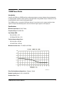
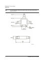
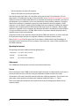
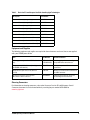
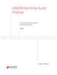
Keysight 11636B APC-3.5 mm Power Divider DC to 26.5 GHz Operating and Service Manual Notices © Keysight Technologies 1985, 2013, 2014 No part of this manual may be reproduced in any form or by any means (including electronic storage and retrieval or translation into a foreign language) without prior agreement and written consent from Keysight Technologies as governed by United States and international copyright laws. Manual Part Number 11636-90001 Edition August 2014 Supersedes: February 1985 Keysight Technologies 1400 Fountaingrove Parkway Santa Rosa, CA 95403 Warranty The material contained in this document is provided “as is,” and is subject to being changed, without notice, in future editions. Further, to the maximum extent permitted by applicable law, Keysight disclaims all warranties, either express or implied, with regard to this manual and any information contained herein, including but not limited to the implied warranties of merchantability and fitness for a particular purpose. Keysight shall not be liable for errors or for incidental or consequential damages in connection with the furnishing, use, or performance of this document or of any information contained herein. Should Keysight and the user have a separate written agreement with warranty terms covering the material in this document that conflict with these terms, the warranty terms in the separate agreement shall control. Technology Licenses The hardware and/or software described in this document are furnished under a license and may be used or copied only in accordance with the terms of such license. Restricted Rights Legend If software is for use in the performance of a U.S. Government prime contract or subcontract, Software is delivered and licensed as “Commercial computer software” as defined in DFAR 252.227-7014 (June 1995), or as a “commercial item” as defined in FAR 2.101(a) or as “Restricted computer software” as defined in FAR 52.227-19 (June 1987) or any equivalent agency regulation or contract clause. Use, duplication or disclosure of Software is subject to Keysight Technologies’ standard commercial license terms, and non-DOD Departments and Agencies of the U.S. Government will receive no greater than Restricted Rights as defined in FAR 52.227-19(c)(1-2) (June 1987). U.S. Government users will receive no greater than Limited Rights as defined in FAR 52.227-14 (June 1987) or DFAR 252.227-7015 (b)(2) (November 1995), as applicable in any technical data. Safety Notices CAU TI O N A CAUTION notice denotes a hazard. It calls attention to an operating procedure, practice, or the like that, if not correctly performed or adhered to, could result in damage to the product or loss of important data. Do not proceed beyond a CAUTION notice until the indicated conditions are fully understood and met. WA RN ING A WARNING notice denotes a hazard. It calls attention to an operating procedure, practice, or the like that, if not correctly performed or adhered to, could result in personal injury or death. Do not proceed beyond a WARNING notice until the indicated conditions are fully understood and met. 11636B Power Divider Introduction From DC to 26.5 GHz, the 11636B provides excellent output power symmetry between the two output ports. Its design provides excellent source match for fault applications using network analyzers. However, it is not recommended for ratio or source leveling applications. The 11636B provides a symmetrical 6 dB power division. It can also be used as a power combiner: when signals are input at the two output ports, the sum of the two signals appears at the input port. Specifications Maximum Input Power: 0.5 W (27 dBm) Frequency Range: DC to 26.5 GHz Input/Output SWR: • DC to 10.0 GHz: 1.22 • 10.0 GHz to 26.5 GHz: 1.29 Tracking Between Output Ports: • DC to 18.0 GHz: <0.25 dB • 18.0 to 26.5 GHz: <0.50 dB Maximum Insertion Loss: <7.5 dB (DC to 26.5 GHz) Phase Tracking Between Output Arms: <3 degrees, Typical Nominal Insertion Loss: 6.0 dB + 0.04 dB/GHz Number of Ports: Three 11636B Operating and Service Manual 1 Connectors: 3.5 mm on all ports Dimensions: NOTE 2 In the following graphic, dimensions are given in inches (cm) and are maximum unless otherwise specified. 11636B Operating and Service Manual Mating the 11636B Power Divider with Other Precision 3.5 mm Devices The 11636B power divider has precision 3.5 mm connectors, and is best used with other precision 3.5 mm devices. When mating connectors, observe the following precautions: • Push them straight together. • Make sure the male contact pin is precisely aligned with the female. • Do not overtighten the connectors. • NEVER rotate either center conductor (by turning the device body). • Only turn the outer nut of the male connector. • Torque to 8 in-lb (96 N-cm) for the final connection. An 8 in-lb torque wrench is available from Keysight. For the part number, refer to “Equipment and Supplies” on page 5. Mating the 11636B Power Divider with SMA Devices CAUTION SMA connectors are not precision devices, and are often out of mechanical tolerances even when new. Out of tolerance SMA connectors will likely ruin a precision 3.5 mm connector on the first mating. Gage SMA connectors before use. The 11636B power divider has precision 3.5 mm connectors. SMA connectors will mate with precision 3.5 mm connectors. However, caution is necessary to prevent accidental damage due to worn or out-of-tolerance SMA connectors. Such connectors can destroy a precision 3.5 mm connector even on the first connection. Keysight Technologies recommends that you remember the following important information: • SMA connectors are not precision mechanical devices. • They are not designed for repeated connections. • They are very susceptible to mechanical wear. • SMA connectors are often out of mechanical tolerances when new. Before mating an SMA connector (even a new one) to a precision 3.5 mm connector, inspect the SMA connector carefully both visually and mechanically. To measure the mechanical tolerances, use a precision connector gage. A male SMA connector pin which is too long can smash or break the delicate fingers on the precision 3.5 mm female connector, damaging it beyond possibility of repair. Gaging SMA connectors is the most important step in preventing damage to your equipment, and it takes very little time. Gaging instructions and gage part numbers are provided in the Connector Care for RF and Microwave Coaxial Connectors document. It can be viewed online by searching for part number 08510-90064 at www.keysight.com. Use the following precautions when mating SMA and precision 3.5 mm connectors: • Push them straight together. • Make sure the male contact pin is precisely aligned with the female. • Do not overtighten the connectors. • NEVER rotate either center conductor (by turning the device body). 11636B Operating and Service Manual 3 • Only turn the outer nut of the male connector. • Torque to 5 in-lb (50 N-cm) for the final connection. Note that the torque listed above is less than when mating two precision 3.5 mm connectors. A 5 in-lb torque wrench is available from Keysight. For the part number, refer to “Equipment and Supplies” on page 5. Significant structural and dimensional differences exist between these two type of connectors. Precision 3.5 mm connectors use an air dielectric. Only air exists between the center and outer conductors. The male or female center conductor is supported by a plastic bead, deep within the body of the connector. In SMA connectors, a plastic dielectric supports the entire length of the center conductor. In addition, the diameters of both the inner and outer conductors differ between SMA and precision 3.5 connectors. When an SMA connector is mated with a 3.5 mm connector, the connection will exhibit a discontinuity mismatch (SWR) of 1.10 typical at 20 GHz (return loss = 26.5 dB). SMA and 3.5 mm connectors should be mated only when a high connector mismatch can be tolerated. Using only precision 3.5 mm connectors will provide superior SWR and insertion loss. It will also extend the life of your power divider (and other test equipment connectors) by reducing mechanical wear. Refer to Table on page 6 for a list of precision 3.5 mm adapters available from Keysight Technologies. A precision 3.5 mm (m) to precision 3.5 mm (m) adapter, or precision airline, can be used to extend the life of the 11636B connectors. Operating Environment The operating environment should be within the following limits: Temperature 0 to +55C (+32 to +131F) Humidity Up to 95% relative Altitude Up to 4.572 meters (15,000 feet) Adjustments The 11636B power divider requires no electrical or mechanical adjustments. Service The circuit elements of the 11636B are split into three identical channels. A malfunction will usually occur in only one channel and can be verified by moving the connection to another channel of the divider. An ohmmeter can be used to check the continuity of the inner conductor connections. The resistance from either output center conductor to the input center conductor should be 33.3 ohms +/– 2 ohms. There are no replaceable components for the power divider. A worn or damaged power divider must be replaced in whole. 4 11636B Operating and Service Manual Table 1 Precision 3.5 mm Adapters Available from Keysight Technologies Description Part Number Precision 3.5 mm (m) to type-N (m) 1250-1743 Precision 3.5 mm (m) to type-N (f) 1250-1750 Precision 3.5 mm (f) to type-N (m) 1250-1744 Precision 3.5 mm (f) to type-N (f) 1250-1745 Precision 3.5 mm (m) to Precision 7 mm 1250-1746 Precision 3.5 mm (f) to Precision 7 mm 1250-1747 Precision 3.5 mm (m) to Precision 3.5 mm (m) 85027-60007 Precision 3.5 mm (f) to Precision 3.5 mm (f) 85027-60005 Precision 3.5 mm (m) to Precision 3.5 mm (f) 85027-60006 Equipment and Supplies The following equipment and supplies are required for the maintenance and use of, but are not supplied with, your 11636B power divider. Item Part Number Recommended Use 3.5 mm gage sets (part of the 85052B calibration kits) 11752-60105 (f) 11752-60106 (m) Periodic gaging of connectors. Gage every SMA connector before use. Torque wrench, 5/16”, 96 N-cm (8 in-lb) (part of the 85052B calibration kit) 8710-1765 Mating two precision 3.5 mm connectors. Torque wrench, open-end, 5/16”, 60 N-cm (5 in-lb) 8710-1582 Mating a precision 3.5 mm connector to an SMA. connector. Document: Connector Care for RF and Microwave Coaxial Connectors 08510-90064 Following instructions on using and maintaining coaxial connectors. Cleaning Connectors For information on cleaning connectors, refer to the Connector Care for RF and Microwave Coaxial Connectors document. It can be viewed online by searching for part number 08510-90064 at www.keysight.com. 11636B Operating and Service Manual 5 Contacting Keysight Assistance with test and measurement needs and information on finding a local Keysight office are available on the Web at: www.keysight.com/find/assist NOTE 6 In any correspondence or telephone conversation, refer to the Keysight product by its model number and full serial number. With this information, the Keysight representative can determine whether your product is still within its warranty period. 11636B Operating and Service Manual This information is subject to change without notice. © Keysight Technologies 1985, 2013, 2014 August 2014 *11636-90001* 11636-90001 www.keysight.com