1
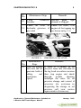
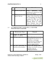
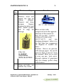
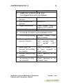
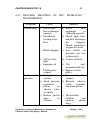
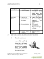
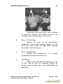
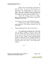
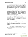
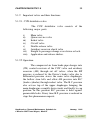
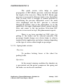
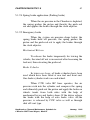
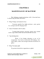
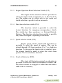
dsoy dk;Zky;hu mi;ksx gsrq
(For Official Use Only)
Hkkjr ljdkj GOVERNMENT OF INDIA
jsy ea=ky; MINISTRY OF RAILWAYS
Handbook on General Maintenance
Schedule for OHE Tower Wagon
MarkMark-III
CAMTECH/2002/E/TW/1.0
January, 2002
Centre
for
Advanced
Maintenance
TECHnology
Execellence in Maintenance
Maharajpur, GWALIOR - 474 005
FOREWORD
Indian Railways uses large number of Tower wagons for
maintenance of overhead equipment in electrified section. The
proper maintenance of tower wagon is vital to ensure its
availability and reliability.
CAMTECH has prepared this hand book to cover all
essential aspects of tower wagon maintenance.
This handbook describes various maintenance schedules,
trouble shooting instructions and do's and don'ts. It also covers
operating and maintenance instructions for OHE car driver.
I am sure the book will prove to be very useful to our
field personnel to carry out their work more effectively and
efficiently.
CAMTECH, GWALIOR
DATE: 17.01.02
M.L.GUPTA
EXECUTIVE DIRECTOR
PREFACE
Tower Wagon is an important vehicle for regular
inspection and attending breakdown of O.H.E. Therefore proper
maintenance of tower wagon is necessary to ensure the reliability
and availability of tower wagon in emergency and for regular
maintenance of OHE. This handbook on "Maintenance of Tower
Wagon" has been prepared by CAMTECH with the objective of
making our maintenance personnel aware to correct maintenance
and maintenance techniques adopted in field
It is clarified that this handbook does not supersede any
provisions laid down by RDSO or Railway Board.
I am sincerely thankful to Director(TI)/RDSO/LKO for
his valuable suggestions and comments. I am also thankful to all
field personnel who helped us in preparing this handbook.
Technological upgradation and learning is a continuous
process. Hence feel free to write to us for any addition/
modification in this handbook. We shall highly appreciate your
contribution in this direction.
CAMTECH, GWALIOR
DATE: 17.01.02
RANDHAWA SUHAG
DIRECTOR/ELECT
CONTENTS
Chapter
No.
Contents
Page
No.
FOREWORD
PREFACE
CONTENTS
CORRECTION SLIP
v
vii
ix
xv
1.
INTRODUCTION
1.1
Body Structure
01
02
2.
LIFTING, SWIVELING PLATFORM AND
PANTOGRAPH
2.1
Pantograph
03
04
3
MAINTENANCE OF ENGINE
3.1
'A; Check Every Day
3.2
'B' Check Every 300 Hours or 6 months
which ever is earlier
3.3
'C' Check Every 1500 Hours or 6 months
which ever is earlier
3.4
'D' Check Every 6000 Hours or 2 years
which ever is earlier
3.5
'E' Check
06
06
09
13
16
17
Chapter
No.
4
Contents
Page
No.
TRANSMISSION
4.1
4.2
4.3
4.4
4.5
4.6
4.7
Maintenance of VOITH Hydraulic
Transmission
Maintenance of Hindustan Motor
Hydraulic Transmission
Trouble Shooting of H.M. Hydraulic
Transimission
Maintenance of VENTRA Drop Gear Box
VENTRA Axle Drive Maintenance
Schedule
Maintenance of KPC Hydraulic
Transmission
K.P.C. Axle drive Maintenance Schedule
18
19
20
23
26
27
29
34
5.
BRAKE SYSTEM
5.1
Air Pressure System
5.2
Maintenance of the Valves
37
37
44
6.
TXR CHECKING
46
7.
ELECTRICAL MAINTENANCE
7.1
Trip Schedule
7.2
Fortnightly Schedule
7.3
Monthly Schedule
7.4
Quarterly Schedule
7.5
Half Yearly Schedule
7.6
Yearly Schedule
47
47
48
48
49
49
49
Chapter
No.
Contents
Page
No.
8.
MAINTENANCE OF BATTERY
50
8.1
Hydrometer reading and battery condition 51
9.
IMPORTANT OPERATING AND
MAINTENANCE INSTRUCTIONS
FOR DRIVERS OF OHE CAR
9.1
9.2
9.3
9.4
10.
Description and operating principle
Stationary Condition
Running Condition
Change of Cabin
DO'S and DON'TS
10.1 Do's
10.2 Don'ts
10.3 Suggestion for achieving zero Failure
10.4 Maintenance Step for Engine
Annexure A -
Annexure B-
Techanical Specification of
Tower Wagon
Oil Change
52
52
56
59
59
60
60
61
62
63
64
73
76
REFERENCE
******
ISSUE OF CORRECTION SLIPS
The correction slips to be issued in future for this
handbook will be numbered as follows:
CAMTECH/2001/E/CL/TW # XX date----------Where “XX” is the serial number of the concerned
correction slip (starting from 01 onwards).
CORRECTION SLIPS ISSUED
Sr. No.
Date of
issue
Page no. and Item
no. modified
Remarks
CAMTECH/2002/E/TW/1.0
CHAPTER 1
INTRODUCTION
Tower wagon has a key role in the maintenance
of OHE and for attending of breakdown, restoration of
damaged OHE equipment and erection of small length
catenary and contact wires. It is also used for inspection,
patrolling and maintenance of overhead equipment. The
satisfactory up keep of tower wagon is therefore of
utmost importance. It is the direct responsibility of tower
wagon incharge to ensure that the tower wagon is
maintained satisfactorily and is available always for
attending OHE maintenance and for use in the event of
OHE breakdown. This handbook deals with details of
schedule maintenance to be carried out by OHE depots.
POH facilities are not available in OHE depots
and therefore POH of complete tower wagon including
engine, running gear arrangement, brake rigging, wheel
and axle, roller bearing, pneumatic valves, lifting and
swiveling platform, hydraulic transmission, axle drive,
bogie, electrical equipment and all under frame
equipment shall be carried out at an interval of three
years in an EMU shop/ Electric Loco shed/ Electric Loco
workshop as decided by CEE. This handbook does not
include details of work to be carried during POH of
tower wagon in EMU shop/Electric Loco shed/Electric
Handbook on General Maintenance Schedule for
January, 2002 4 Wheeler OHE Tower Wagon, Mark III
2
CAMTECH/2002/E/TW/1.0
Loco workshop. Similarly work to be carried out by
TXR during monthly examination is not included in this
handbook as this handbook is intended for the staff of
OHE depots only.
1.1
BODY STRUCTURE
The body of the tower wagon is built up by iron
sheets supported on the large frame work erected on the
under frame.
Tower wagon’s inside is divided into two driving
cabs with seating arrangement for driver and supervisor
and central portion. The central portion is having various
racks and pigeon holes on one side and lattice enclosure
on the other side. A space is left at the centre for the staff
to work.
All the enclosures are used for preserving the
materials and tools for attending OHE maintenance and
breakdowns.
The roof of the tower wagon is mounted with
iron corrugated sheet and strengthen for staff to work on
the top. It is also mounted with lifting and swiveling
platform at one end while the other end is having
pantograph.
*****
Handbook on "General Maintenance Schedule for
4 Wheeler OHE Tower Wagon, Mark III"
January, 2002
3
CAMTECH/2002/E/TW/1.0
CHAPTER 2
LIFTING AND SWIVELING
PLATFORM AND PANTOGRAPH
Lifting and swiveling platform measuring with in the
permissible limits is mounted on the one end of the roof for
raising its height and rotating it by 360°. The arrangement is
such that when the maintenance staff has to work near the
structure , the platform can be rotated so that it reaches the
structure and facilitates the working of the staff. Similarly
height of the plat- form can be adjusted to suit the working spot
on overhead equipment. This has got the chain pulley and gear
system and having its operating arrangement on the top by
means of a handle.
The platform is surrounded from all the three sides (other
than panto side) with collapsible railing of pipe. These railings
can be lifted up as and when the staff works on the roof
otherwise these are normally kept lowered on the platform and
thus the moving dimensions are maintained.
Handbook on "General Maintenance Schedule for
4 Wheeler OHE Tower Wagon, Mark III"
January, 2002
4
CAMTECH/2002/E/TW/1.0
2.1
PANTO GRAPH
Pantograph is similar to that used for AC loco but having
spring control only.
The required pressure of panto is adjusted by means of
control springs at the bottom. It is mounted on the centre line
along the roof of the tower wagon at the other end. The height of
the panto is adjusted suitably to meet the requirement of
overhead equipment
On panto pan the marking of stagger is done. Similarly
the height gauge is also fitted to the pantograph. This facilitates
recording of the stagger and height of the contact wire
respectively.
FIGURE 2.1 PANTOGRAPH LOWERED CONDITION
Handbook on "General Maintenance Schedule for
4 Wheeler OHE Tower Wagon, Mark III"
January, 2002
5
CAMTECH/2002/E/TW/1.0
FIGURE 2.2 PANTOGRAPH RAISED CONDITION
Details of figure 2.1 and 2.2
S.
1.
2.
3.
4.
5.
6.
7.
8.
9.
Details
Base
Horizontal Spindle
Lower Arm
Yoke
Tube
Upper Tube
Thrust Rod
Pivot point
Transverse Tube
S.
10.
11.
12.
13.
14.
15.
16.
17.
18.
Details
Joint of upper tube
Spring Box
Positioning Link
Lifting Spring
Servo Motor
Tie rod insulator horn
Collector
Insulated Horn
Support Insulator
*****
Handbook on "General Maintenance Schedule for
4 Wheeler OHE Tower Wagon, Mark III"
January, 2002
6
CAMTECH/2002/E/TW/1.0
CHAPTER 3
MAINTENANCE OF ENGINE
3.1
‘A’ CHECK EVERY DAY
S.
No
Maintenance Steps
Remarks
1.
Check previous day’s
Correct as required.
engine log book.
2.
Drain
water
and
sediment from fuel Before
filter through drain engine.
cock.
3.
starting
the
Must be slightly less than
Check engine oil level
or equal to ‘H’ mark on
and
top
up
if
dip stick when engine is
necessary.
stopped and has stood for
20 minutes or more (must
be measured after all oil
is drained back into oil
pan).
Handbook on "General Maintenance Schedule for
4 Wheeler OHE Tower Wagon, Mark III"
January, 2002
7
CAMTECH/2002/E/TW/1.0
S.
Maintenance Steps
No
4. Check for fuel, oil,
water and exhaust
leaks.
5. Fill radiator/surge tank
with treated water
(chromate
concentration
3500
PPM)
6.
7.
8.
9.
Remarks
Correct if leaking.
Radiator cap must be
firmly tightened back
into the radiator/surge
tank neck. Engine must
not be operated without
the aeration and
overheating of the
coolant. Check engine
radiator water level.
Check air cleaner oil Use clean engine oil.
level and change oil, if
required (If oil bath
type). Clean dustpan
and pre- cleaner of dry
type air cleaner.
Check air
line Correct as required.
connections for leaks.
Remove and clean air Fill with clean oil upto
compressor breather, if the mark.
equipped.
Drain air receiver tank
at the beginning of
every day and then
close the drain cock.
Handbook on "General Maintenance Schedule for
4 Wheeler OHE Tower Wagon, Mark III"
January, 2002
8
CAMTECH/2002/E/TW/1.0
S.
No
10.
Maintenance Steps
Clean
breather.
Remarks
crankcase Discard paper type
element if clogged.
Check oil level in Check for leaks. Use
11. hydraulic governor, if engine oil for topping up
provided
(as shown in fig. 3.1)
FIGURE 3.1
S.
Maintenance
No
Steps
12. Start the engine
and note the oil
pressure both at
idling
and
maximum
speed.
CHECKING OF OIL LEVEL
Remarks
If there is a change in oil
pressure from that recorded in
the log book on earlier occasion
then stop engine and check
through
trouble
shooting
technique the cause for oil
pressure change and correct if
necessary (for assistance in
diagnosing the change in oil
pressure call your service
representative if necessary.
Handbook on "General Maintenance Schedule for
4 Wheeler OHE Tower Wagon, Mark III"
January, 2002
9
CAMTECH/2002/E/TW/1.0
S. Maintenance Steps
Remarks
No
13. Record oil pressure. Refer
operation
and
maintenance manual for lub
oil pressure limits.
14. Fill fuel tank at the Use clean fuel and a
end of the day.
strainer. Also clean the cap
and surrounding area before
opening the filler cap. Fill
fuel at end of the day
allowing diesel to settle.
Drain sediment from fuel
filter water separator bowl.
3.2
‘B’ CHECK EVERY 300 HOURS or 6 MONTHS
WHICH EVER IS EARLIER
S.
Maintenance Steps
Remarks
No
1. Repeat all maintenance -steps of ‘A’check
2. Change engine oil.
When lub oil is examined
through lub oil analysis in a
laboratory, oil change
period may be extended. In
such cases, refer to your
service representative.
3. Fit new lubricating oil Inspect the changed filter
full flow filter element.
element and check for metal
particles and oil
sludging/oxidation.
Handbook on "General Maintenance Schedule for
4 Wheeler OHE Tower Wagon, Mark III"
January, 2002
10
CAMTECH/2002/E/TW/1.0
S.
No
4.
Maintenance Steps
Remarks
Remove, clean and
inspect dry type air
cleaner
element.
Remove and clean
dustpan.
Inspect
FIG. 3.2 AIR CLEANER
element for holes and
tears. Check gaskets
and ‘O’ rings for Blow out dust with
damage.
compressed air in the opposite
direction of the normal air
flow. If very dirty , wash in
solution of warm water.
(48.9°C-60°C)
and
non
sludging detergent. Allow it to
dry first then use compressed
air. Replace if washed two
times.
Caution : Excess air pressure
will damage paper. Air nozzle
FIG. 3.3
must be kept at least 8” from
ELEMENT
the element. Must not be used
CHECKING
if even one pin hole exists.
WITH ELECTRIC
Discard element if punctured
and also change gasket along
with element.
5.
Clean oil bath air
----cleaner tray screen.
Handbook on "General Maintenance Schedule for
4 Wheeler OHE Tower Wagon, Mark III"
January, 2002
11
CAMTECH/2002/E/TW/1.0
S.
No
6.
7.
8.
9.
Maintenance Steps
Remarks
Change lubricating
oil by-pass filter
Record oil pressure
element and gasket if
provided.
Clean float tank
and/or main fuel tank ----breather.
Check coolant PH
value/concentration
of
DCA/chromate
concentration (3500
PPM).
Change corrosion resistor
element if PH calue is
below normal range 8.5 –
10.5.
Check chromate
concentration at 3500 PPM.
Check
magnesium
plate in assembly
corrosion
resistor.
Change water filter
element.
Check magnesium plate for
pitting or being eaten away.
Change if more than 50% of
area is lost. Use DCA
service element or chromate
element bags AR 95679 if
concentration is low.
Clean shell fuel filter.
Change
element
when
restriction exceeds vacuum
20.32cm of mercury.
Use same oil as used in oil
pan.
10. Change fuel filter
element washer and
‘O’ ring on mounting
bolt.
11. Check oil in aneroid
control, If equipped.
Handbook on "General Maintenance Schedule for
4 Wheeler OHE Tower Wagon, Mark III"
January, 2002
12
CAMTECH/2002/E/TW/1.0
S.
No
Maintenance Steps
Remarks
Tighten belt tension (use
ST – 1293)
Check and adjust belts.
New belts will stretch
12.
within one hour of use.
They must be readjusted.
FIG. 3.4 CHECK BELT
TENSION
Tighten foundation bolts
and flexible coupling
13.
bolts of engine and
alternator.
-----
Check all air cleaner
connections for cracks- Correct as required.
14.
chafing etc. Tighten all
air intake connections.
15. Check fan hub and drive.
Clean/change
16. compressor
element.
Use special tool no. ST
845 or ST 893 for
tightening the fan hub
nut.
Change element for
air
naturally
aspirated
breather
engine. Clean screen for
turbo engine.
17. Check throttle linkage.
Handbook on "General Maintenance Schedule for
4 Wheeler OHE Tower Wagon, Mark III"
-----
January, 2002
CAMTECH/2002/E/TW/1.0
3.3
13
‘C’ CHECK EVERY 1500 HOURS or 1 YEAR WHICH
EVER IS EARLIER
S.
Mainten
Remarks
No
ance Steps
1. Repeat all maintenance
steps of checks ‘A’ & ---‘B’.
2.
It should start opening and
open fully within range
73.9°C and 79.5°C or
Check
thermostat
76.6°C and 85° C. Discard
operation.
and fit new thermostat if
operation
is
not
satisfactory.
3. Check fan hub and Check mounting bolts and
drive.
bearing end play.
4. Check impeller water
Correct if necessary.
pump for play.
5. Check for turbocharger
Correct as required.
oil leaks.
6.
Tighten to the specified
Tighten turbocharger
torque. Do not tighten
mounting nuts.
when engine is hot.
7.
Check after cleaning dry
type air cleaner element . If
Check
inlet
air
restriction in excess of
restriction.
63.5cm water, a new
element must be fitted.
8.
Remove complete
Clean oil bath air
assembly and clean
cleaner.
inclusive of fixed screens.
Handbook on "General Maintenance Schedule for
4 Wheeler OHE Tower Wagon, Mark III"
January, 2002
CAMTECH/2002/E/TW/1.0
14
S.
Mainten
Remarks
No
ance Steps
9. Clean and tighten all ----electrical connections.
10. Check
generator Replace and clean as
brushes
and
required.
commutators.
11. Clean entire engine.
High pressure and soap
water mixture preferred
after spraying engine with
cleanser taking care of
protecting
electrical
system.
12. Tighten all mounting Tighten as required. Over
bolts and nuts.
tightening may result in
distortion or damage.
13. Clean
aneroid
air Replace
breather
if
breather.
necessary.
14. Check engine blowby.
15. Clean radiator.
Handbook on "General Maintenance Schedule for
4 Wheeler OHE Tower Wagon, Mark III"
Readings in excess of
recommended limits.
Corrective action must be
taken through analysis with
the help of trouble shooting
chart.
Blow air through the
radiator core in opposite
direction to the normal
flow of air, if working
under dusty/dirty
condition.(Reverse
flushing operation)
January, 2002
15
CAMTECH/2002/E/TW/1.0
S.
No
Mainten
ance Steps
Remarks
16. Check air compressor
Check shaft and clearance.
Adjust injectors and Clean fuel inlet connection
valves.
screens. Final adjustments
must be carried out with
17.
engine hot and with correct
torque as specified (Refer
O & M manual).
Change
18. governor
oil.
19.
Check
damper.
hydraulic
Use engine lubricating oil.
oil/aneroid
Check
wobble
and
eccentricity/alignment
vibration marks on rubber type.
Discard
damper
if
misalignment is more than
0 .16 cm.
Handbook on "General Maintenance Schedule for
4 Wheeler OHE Tower Wagon, Mark III"
January, 2002
16
CAMTECH/2002/E/TW/1.0
3.4
‘D’ CHECK EVERY 6000 HOURS or 2 YEARS
WHICH EVER IS EARLIER
S.
Maintenance Steps
Remarks
No
1. Repeat all maintenance
-steps of checks ‘A’, ‘B’
& ‘C’.
2. Check exhaust and inlet
-manifold
nuts
and
capscrews.
3. Tighten all mounting
-bolts and nuts.
4. Clean
turbocharger
-diffuser and impeller
and check end float.
5. Check
turbocharger Only end float on semi
bearing clearances.
floating bearing if in
excess of limits, replace
it.
6. Check crankshaft end If
in
excess
of
float.
recommended
limits,
corrective action is
indicated.
7. Clean injector inlet Must be done only if a
screens
performance
deterioration is evident.
Some of the indications
for
performance
deterioration are.
1.
Black smoke.
Handbook on "General Maintenance Schedule for
4 Wheeler OHE Tower Wagon, Mark III"
January, 2002
17
CAMTECH/2002/E/TW/1.0
S.
No
Maintenance Steps
Remarks
2.
3.
4.
5.
6.
7.
8.
9.
3.5
Change in fuel
manifold pressure.
Loss of power.
Malfunction
of
aneroid.
Clean and calibrate
all injectors.
Check fuel pump
calibration.
Replace
aneroid
bellows
and
calibrate
Replace fuel pump -filter screen and
magnet.
Steam clean engine.
If steam is not available,
then use clean soap water
solution as outlined in ‘C’
check item – 11.
'E' CHECK Overhauling Of Engine After Two 'D' Check
******
Handbook on "General Maintenance Schedule for
4 Wheeler OHE Tower Wagon, Mark III"
January, 2002
CAMTECH/2002/E/TW/1.0
18
CHAPTER 4
TRANSMISSION
The transmission and control equipment were supplied
by two firms viz. M/s Kirloskar Pneumatic Co. Ltd., Pune and
M/s Venkateswara transmission private Ltd. (VENTRA)
Hyderabad. Hydraulic transmission offered by M/S KPC is of
their own design and that of M/s Ventra is of Hindustan Motors.
However five numbers 4 wheeler tower wagons were provided
with Voith transmission system.
A common power pack is used for both the two designs.
A Kirloskar Cummins Ltd. model N-743-L naturally aspirated
diesel engine developing 210 horsepower at 2100 rpm has been
used. The transmission of both powers from diesel engine to
wheels is by means of hydrodynamic system incorporating
torque converter and gears.
The final power transmission in both designs is through
carden shaft and axle drives. In the KPC design the transmission
output is directly connected to the axle drive on the rear axle by
means of a long cardan shaft using axle drives of two different
overall gear ratios. This transmission also incorporates reversing
arrangements with the use of plate clutch unit.
In the VENTRA design the transmission output is
connected to the axle drive through an intermediate gearbox of a
differential gear unit and a hydrodynamic torque converter
incorporating speed change provision. The final drive from
diesel engine is through a slip- clutch assembly properly aligned
with in the engine fly-- wheel housing.
Handbook on "General Maintenance Schedule for
4 Wheeler OHE Tower Wagon, Mark III"
January, 2002
19
CAMTECH/2002/E/TW/1.0
4.1
MAINTENANCE
TRANSMISSION
OF
VOITH
HYDRAULIC
4.1.1 Maintenance Schedules
Maintenance interval Work to be performed
20,000 km
Check oil level
300,000 km
Oil change, inspection of control
parts, replacement of filter,
replacement of disposable filter.
900,000 km
Major overhaul
4.1.1.1 Maintenance after 20,000 km
Check the oil level.
4.1.1.2 Maintenance after 300,000 km
a)
Oil change
Under normal operating conditions, the
oil filling lasts for a distance of approx..
300,000km . This period can be extended if the
oil sample is still with in the tolerance of the
specification for new oil.
For changing the oil, drain it from valve
while it is at operating temperature and drain the
oil cooler too. If oil of a different approved brand
is to be filled in, flush the transmission and
cooling system with half the quantity of the new
oil needed for a complete fill.
Handbook on "General Maintenance Schedule for
4 Wheeler OHE Tower Wagon, Mark III"
January, 2002
CAMTECH/2002/E/TW/1.0
20
b)
Replace all filters. For this purpose, drain off the
oil first, then remove the filters, take off the caps
and remove filter elements.
c)
Check control parts such as governor, standstill
detector valve, operating cylinder, and main
control valve for proper operation, leakage and
wear.
4.1.1.3 Major Overhaul
A major over haul of the transmission is
recommended after approx. 900,000 km of operation,
depending on operating conditions and duty. During this
over haul, the transmission is stripped as far as
necessary. Bearing labyrinth rings, shaft seats etc. are
inspected and damaged parts are replaced.
4.2
MAINTENANCE
OF
HINDUSTAN
HYDRAULIC TRANSMISSION
MOTOR
4.2.1 Control Linkage
Check the transmission shift control linkage and
the directional linkage to ensure that the linkages are free
and that the selector levers are properly positioned. The
Shift levers should engage in all shift tower positions
freely. Inspect the linkages for binding, wear, cracks,
breaks or defective cotter pins.
Handbook on "General Maintenance Schedule for
4 Wheeler OHE Tower Wagon, Mark III"
January, 2002
CAMTECH/2002/E/TW/1.0
21
4.2.2 Cold Oil Level Check
The cold check (engine not running) is made to
determine if there is sufficient oil to safely start the
engine - especially if the vehicle has been idle. The oil
level should be at or near the full-level check plug. Some
transmissions have one plug, others have two plugs, an
ADD and a FULL plug.
4.2.3 Hot Level Check
Oil level must be checked with the engine
running at 1000 rpm, transmission in neutral and with
the transmission at normal operating temperature
(82.3°C - 93.4°C). The upper check plug (if there are
two plugs) indicates the full oil level while the lower
plug is the add level. The oil must be maintained at the
FULL level. If there is only one check plug, the oil level
must be maintained at this level. Add oil if necessary to
bring the level to the FULL mark.
4.2.4 Oil, Filter Change
The oil should be changed every 1000 hours of
operation or sooner, depending upon operating
conditions. Also, the oil must be changed whenever there
are traces of dirt or evidence of high temperature
indicated by discoloration or strong odor. The filter
screen in the sump should be removed and cleaned with
mineral spirits at each oil change.
The filter elements should be replaced at each oil
change and at 200 hour intervals between oil changes.
Handbook on "General Maintenance Schedule for
4 Wheeler OHE Tower Wagon, Mark III"
January, 2002
CAMTECH/2002/E/TW/1.0
22
The filter shells should be cleaned. New gaskets and seal
rings must be used when replacing filter elements. After
installation, check the filter for oil leakage while the
vehicle engine is running.
4.2.5
Keeping oil clean
It is absolutely necessary that the oil put in the
transmission be clean. Oil must be handled in clean
containers, filler etc., to prevent foreign material from
entering the system.
4.2.6
Filling Transmission
At temperature above -23.3°C, pour hydraulic
transmission fluid type C-2 into filler opening. At
temperature below -23.3°C, an auxiliary preheat is
required to raise the temperature in the sump. Use only
C-2 fluids from approved manufacturers.
4.2.7
Care of Breather
The breather should be kept clean at all times. It
should be checked and cleaned regularly and as
frequently as necessary, depending upon the operating
conditions. A badly corroded or plugged breather
restricts proper breathing, causing oil leaks.
4.2.8
Control Linkage Adjustment
Manual shift linkage must be adjusted so that the
operator's control is positioned to exactly match the
detent position of the selector valve on the transmission.
Adjust the linkage so that it can be freely connected
without moving either the valve or the operator's control.
Handbook on "General Maintenance Schedule for
4 Wheeler OHE Tower Wagon, Mark III"
January, 2002
23
CAMTECH/2002/E/TW/1.0
Then operate the range selector lever, the directional
selector lever and the output disconnect (if applicable)
through each position. Make minor adjustments, if
necessary, to insure that each of the selector levers seats
in each position of the operator's control. Then inspect
the control linkage for binding wear or breaks.
4.3
TROUBLE SHOOTING
TRANSMISSION
OF
Causes
HM
HYDRAULIC
Remedy
A. LOW CLUTCH APPLY PRESSURE
1.
2.
3.
4.
Low oil level
Clogged oil strainer
Clogged oil filter
Inching control
adjustment not fully
retracted
5. Air leak at intake side of
oil pump
6. External oil leakage
7.
8.
B.
1.
2.
Add oil to correct level
Clean strainer
Replace filter element
Check, adjust linkage
Check pump mounting
bolts.
Tighten bolts or replace
gaskets
Brake hydraulic (or air) Check brake residual
pressure applying clutch pressure
(brakes
cutoff valve
released); check brakes
for full release.
Internal failure
Overhaul transmission,
or repair subassembly
OVERHEATING
High oil
Restore proper oil level
Clutch failed
Rebuild transmission
Handbook on "General Maintenance Schedule for
4 Wheeler OHE Tower Wagon, Mark III"
January, 2002
CAMTECH/2002/E/TW/1.0
24
Causes
Remedy
3. Vehicle overloaded
Reduce load
4. Low clutch apply
Refer to A.
pressure
5. Engine water overheated Correct
engine
overheating
6. Cooler oil water line
Clean or replace line
kinked or clogged
C. AERATED (foaming) OIL
1. Incorrect type oil used
2.
3.
4.
5.
D.
1.
2.
3.
E.
1.
2.
Change oil; use proper
type
High oil level
Restore proper oil level
Low oil level
Restore proper oil level
Air entering suction side Check oil pump bolts
of oil pump
and gasket
Air entering at clutch
Check plug seal and
cutoff valve (air
seal ring of valve.
actuated)
VEHICLE WILL NOT TRAVEL
Low clutch apply pressure Refer at A
Selector linkage broken or Repair or connect
disconnected
linkage
Internal mechanical
Overhaul
failure
transmission
VEHICLE TRAVELS IN NEUTRAL WHEN
ENGINE IS ACCELERATED
Selector linkage out of
Adjust linkage
adjustment
Clutch failed (won't
Overhaul
release)
transmission
Handbook on "General Maintenance Schedule for
4 Wheeler OHE Tower Wagon, Mark III"
January, 2002
25
CAMTECH/2002/E/TW/1.0
Causes
Remedy
F. VEHICLE LACKS POWER AND
ACCELERATION AT LOW SPEED
1. Low clutch apply
pressure
2. Low converter out
pressure
3. Engine malfunction
4. Aerated oil
Refer to A
Refer to A
Check engine; refer to
engine service manual
Refer to C
G. CLUTCH CUTOFF VALVE INEFFECTIVE
1. Valve or plug sticking
3. Brake apply air
pressure not reaching
air cylinder
4. Plunger sticking in air
cylinder
Rebuild control valve
body assembly
Check pressure at control
valve (min-max limit -140.7
9.15
kg/cm2
2
kg/cm )
Check air cylinder (15.85
kg force required to
stroke valve)
Check operation of air
cylinder
5. Air entering at valve
(air actuated)
Check operation of air
cylinder (seals)
2. Brake apply hydraulic
pressure incorrect
Handbook on "General Maintenance Schedule for
4 Wheeler OHE Tower Wagon, Mark III"
January, 2002
26
CAMTECH/2002/E/TW/1.0
4.4
MAINTENANCE OF VENTRA DROP GEAR BOX
General
Ventra drop gearbox is a single --stage gearbox,
all the bearing and gear s are adequately rated to give a
longer life. This gearbox transmits the power from
converter/ transmission to the rear axle drive gearbox
through carden shaft of adequate design.
Description
The input flange is key mounted on the input
pinion shaft, which runs on the spherical roller bearings.
The input pinion is meshed with out put gear, which is
key mounted on the out put shaft. The out put flange is
key mounted on out put shaft. The out put shaft runs on
spherical roller bearings. The gears and bearing are
lubricated through pipe by means of a Hypo pump
mounted on the output shaft. Oil seals are provided at
input and out put end to prevent the oil oozing through
the end covers
Maintenance
1. Daily oil level to be checked through the level plug
/indicator, if necessary, top up the oil.
2. Daily check the oil leakage through input, out put oil
seals, through the end cover s and through housing
joints etc. if so, rectify the oil leakage by changing
the new oil seals or by tightening the respective bolts
and nuts.
Handbook on "General Maintenance Schedule for
4 Wheeler OHE Tower Wagon, Mark III"
January, 2002
27
CAMTECH/2002/E/TW/1.0
3. Once in a week take out the magnetic drain plug
from the gear boxes and check for any wear out
particles or debris, if heavier particles found, the gear
box has to be opened and checked.
4. For the new gears, first oil changing period is one
month Then once in three months, the specified oil to
be changed
Note-- Before changing the equivalent oil, clean the
gearbox with kerosene or diesel. Then pour the
equivalent oil and drain out 1/2 to 1 litre of the same
oil through the drain plug. Then put the oil little
above the level plug / indicator
5. Breather must be cleaned thoroughly once in three
months.
4.5
VENTRA
AXLE
SCHEDULE
DRIVE
MAINTENANCE
The final drive to the tower wagon is affected by
the axle mounted right angle drive gear box. The input
and intermediate shaft run spherical roller bearing. The
axle also run on spherical roller bearing the gear box
housings have been provided with oil pockets and gears
and bearings get abundant lubrication. The bottom
housing serves as the oil sump. Level, drain plug and
inspection door have been provided for regular
maintenance.
Handbook on "General Maintenance Schedule for
4 Wheeler OHE Tower Wagon, Mark III"
January, 2002
28
CAMTECH/2002/E/TW/1.0
1. Daily oil level to be checked through the level
plug and if necessary top up with the same oil
(please refer oil chart for quantity/grade).
2. Check for
oil leakage
through oil
seals and
housing
joints. Seal
are to be
replaces or
housings
are to be
tightened
according
to the prescribed tightened torque, if necessary.
3. Once in a fortnightly take out the magnetic drain
plug from the gear box and check for any wear
particles or debris; if heavier particles are found
the gear box has to be inspected by opening the
cover at the top.
Note For Changing Oil
For a new gear box, first oil change shall be done
after one month. During changing, clean the gear box
with kerosene or diesel after draining out the sump. Pour
the recommended/equivalent oil and drain out 1/2 to 1
litre oil again. Close the drain. Fill the sump with
specified quality.
Period of changing oil - every three months.
Handbook on "General Maintenance Schedule for
4 Wheeler OHE Tower Wagon, Mark III"
January, 2002
29
CAMTECH/2002/E/TW/1.0
4.6
MAINTENANCE
TRANSMISSION
OF
KPC
HYDRAULIC
4.6.1 Maintenance
4.6.1.1 Hydraulic system
a.
The oil capacity of
transmission is 20
litres.
b.
Oil level should be
checked
daily
through the oil level
gauge
in
transmission.
Oil
level should be checked at idling engine speed, it
should be between high & low marks.
c.
Oil must be changed after 1000 Hrs. of operation.
d.
Drain valve is provided for draining the oil
without loss. Connect hose to the drain valve and
then open the valve.
e.
Fill the oil in transmission through breather cap
hole. Run the engine and check the oil level.
Replace the breather cap or alternatively, remove
plug provided on cover top & fill oil. Refit plug
after oil filling.
Handbook on "General Maintenance Schedule for
4 Wheeler OHE Tower Wagon, Mark III"
January, 2002
CAMTECH/2002/E/TW/1.0
30
f.
Replace filter element as per recommendations.
Remove the filter cover and replace filter
element. Use new gasket, if necessary, for the
filter cover.
g.
Suction strainer: Unscrew plug on top of strainer
housing for strainer removal. Clean strainer
throughly by flushing in clean diesel oil. All
foreign particles must be removed from the
strainer before refitting it. Ensure air tightness
after replacing plug on housing strainer. Thread
sealing compound may be used to avoid leakage
of air in to the circuit.
h.
Remove the breather assembly every 1000 Hrs.
of operation. Flush the oil breather assembly.
4.6.1.2 Inspection - Daily
a.
Check oil level.
Add if necessary.
b.
Check
all
pipelines,
end
connections
for
leakages. Replace
damaged parts to
stop leakages.
c.
Check all pressure/ temperature gauges for
proper functioning. Replace damaged gauge
immediately.
Handbook on "General Maintenance Schedule for
4 Wheeler OHE Tower Wagon, Mark III"
January, 2002
31
CAMTECH/2002/E/TW/1.0
d.
Check oil leakage from oil seal bolted joints.
Replace damaged oil seals. Tighten loose bolts/
screw to stop leakages from joints.
4.6.1.3. Inspection - Weekly
a
Check strainer and
clean.
b
Check
filters
element and clean
if necessary.
c
Check and tighten
all bolted joints including mounting bolts.
4.6.1.4 Inspection After Each 1000hrs Of Operation
a
Change oil in the sump and fill new
recommended oil
b
Clean selector valve.
c
Check all gauges for their correctness.
4.6.1.5 Periodic Overhaul
A complete over haul of the transmission should
be done simultaneously with overhauling of engine . The
period is aproximately4000Hrs . of operation or 18
month whichever is earlier.
Handbook on "General Maintenance Schedule for
4 Wheeler OHE Tower Wagon, Mark III"
January, 2002
32
CAMTECH/2002/E/TW/1.0
4.6.2 TROUBLE SHOOTING
TRANSMISSION
Symptom
Overheating
OF
Cause
a. Insufficient
heat exchanger
capacity.
b. Insufficient
cooling water
flow.
KPC
a)
b)
c. Clutch slipping.
c)
d. Oil level too
high.
e. Improper oil .
d)
f.
Low
oil a)
pressure
b)
c)
HYDRAULIC
Remedy
Install
heat
exchanger
of
sufficient capacity.
Check pipe lines
and heat exchanger
for
clogging.
Check correctness
of pipe size used.
Low clutch oil
pressure (see low
oil pressure).
Correct oil level.
e) Use
only
recommended oils.
f) Replace clutch
Clutch plates
plates.
warped
Clogged
a) Remove & clean
strainer.
strainer .
Stuck pressure b) Remove selector
regulation
valve
assembly
piston
in
and clean piston.
selector valve
assembly.
Broken piston c) Disassemble
rings
in
clutches
and
clutches.
replace
piston
rings.
Handbook on "General Maintenance Schedule for
4 Wheeler OHE Tower Wagon, Mark III"
January, 2002
CAMTECH/2002/E/TW/1.0
33
Symptom
Cause
Remedy
d) Damaged
or d) Remove oil pump.
worn oil pump
Replace damaged
assly.
/worn assly.
e) Clogged or
e) Remove
orifice
plugged orifice
plate and clean .
plate in
selector valve
assembly.
f) Low oil level. f) Add.
oil
to
maintain proper oil
level.
g) Foamed oil.
g) Check for air leak
in suction line.
No
oil a) Faulty pressure a) Replace pressure
pressure
gauge .
gauge .
b) Low oil level b) Check
or emply sump
gasekets,seals for
.
leakage. Replace
parts
causing
leakage. Maintain
correct oil level.
c) Fully clogged c) Remove &clean it.
oil strainer.
d) Damaged oil d) Replace oil pump.
pump.
Poor
a) Low
oil a) Add
oil
to
performance
pressure.
maintain oil level.
b) Use recommended
b) Improper oil.
oil .
Handbook on "General Maintenance Schedule for
4 Wheeler OHE Tower Wagon, Mark III"
January, 2002
34
CAMTECH/2002/E/TW/1.0
Symptom
Excessive
Noise
Neutral
4.7
Cause
Remedy
c) Clutch slipping c) Disassemble clutch
assemblies. check
clutch plates and
replace worn-out
or damaged plates.
a) Air leak in
a) Check and tighten
suction line of
all joints. Replace
the sump.
damaged
end
fittings/hoses
/pipes.
b) Bearing failure b) Disassemble
transmission.
Replace damaged
bearings.
a)
clutch plates a) Replace clutch
warped.
plates.
KPC AXLE DRIVE MAINTENANCE SCHEDULE
1.
Periodic maintenance
Daily - Check
oil level daily. It
should be at the upper
mark. Refill the oil, if
the level has dropped
below the minimum
mark. Be sure to use
the same oil brand.
Handbook on "General Maintenance Schedule for
4 Wheeler OHE Tower Wagon, Mark III"
January, 2002
CAMTECH/2002/E/TW/1.0
35
Check the bolts and screws and re-tighten
if necessary. Inspect the torque reaction rod
assembly and its mounting to base frame.
2.
Every 375,000 Kms
Subject all parts to an intermediate
inspection. Check the bearing pattern on the
bevel gear drive. Check the taper roller bearings
for proper axial clearances.
3.
Every 750,000 Kms.
Subject all components to a major
inspection and replace if necessary.
4.
Oil Change
After a new axle drive has been in use for
50 Hrs., the oil must be changed. Further oil
change must be made after every 6000 Hours of
operation.
Handbook on "General Maintenance Schedule for
4 Wheeler OHE Tower Wagon, Mark III"
January, 2002
36
CAMTECH/2002/E/TW/1.0
Remove the oil drain plug to drain the oil
from the drive. If excessive metal particle are
detected on the magnetic plug or in the oil, it
shows that some components have rubbed each
other. Open the axle drive and inspect, Remove
the plunger type pump and clean pump strainer.
Clean the housing from oil sludge.
Replace the drain plug. Fill with new filtered oil
through the filler neck.
5.
Axial clearance check, Tapered Roller Bearings:
Proceed in accordance with the guidelines
and instructions. The bearing clearance must be
maintained.
6.
Check of Bearing Pattern, Bevel Gear Drive:
To enable this inspection the axle drive
must be opened. Lightly coat three or four teeth
on bevel pinion with blue colouring. Rotate the
driven gear by hand. Check the bearing pattern
on the contact surfaces. The bearing pattern
should be centered on the working surface or
pointing a little toward the minor diameter. If the
bearing pattern falls short of this requirement,
readjust.
*****
Handbook on "General Maintenance Schedule for
4 Wheeler OHE Tower Wagon, Mark III"
January, 2002
CAMTECH/2002/E/TW/1.0
37
CHAPTER 5
BRAKE SYSTEM
5.1
AIR PRESSURE SYSTEM
5.1.1 Introduction
Air pressure system in the Tower car mark III
carried out the following operations i)
Operation of the brake cylinders
ii)
Control system
iii)
Signal Horns
iv)
Parking brake
When the power pack of tower car works, the
entire air pressure system is charged by the integrated
diesel engine air compressor. The main reservoir
pressure is kept between 7 to 8 kg/cm2 with the help of
governor, time relay auto drain valve (fitted with main
reservoir) and unloader. There is one another Safety
valve set at 9.5 kg/cm2 which can save the air pressure
system in the worst case, when the usual safety valve
(unloader and auto drain valve with time relay) fails.
Handbook on "General Maintenance Schedule for
4 Wheeler OHE Tower Wagon, Mark III"
January, 2002
CAMTECH/2002/E/TW/1.0
38
Duplex pressure gauges have been provided in
both the Dr cabins which will show the M.R. and B.P. of
the air pressure system. Two nos. gauges have been also
provided in the Driver's cabin to show the Brake cylinder
pressure when brake is applied. Another two nos. gauge
have been provided for control system (one in each Dr.’s
cabin) One no. of pressure gauge has been provided on
control box. Which will show the actual pressure
receiving by the control system. There is one air pressure
oiler fitted with service pipe line to control box to
facilitate the lubrication of pneumatic valves and
equipment fitted in control board.
Condemned water from the system can be
removed by means of drainage valve provided in air
supply tanks. There are 4 nos. of brake cylinders (one for
each wheel) to facilitate perfect brake on the tread of
wheels from both sides.
There are two spring brake actuators provided
specially for parking brake. It can park the Tower car
where there is no air in the system. In the normal running
condition due to air pressure brake are in the released
condition.
It will function as emergency brakes when the air
pressure drops below the spring brake hold off pressure,
the spring pushes the piston and the push rod out to
apply the brakes.
Handbook on "General Maintenance Schedule for
4 Wheeler OHE Tower Wagon, Mark III"
January, 2002
CAMTECH/2002/E/TW/1.0
39
5.1.2 Important valves and their functions.
5.1.2.1. C3W distributor valve
The C3W distributor valve consists of the
following major parts.
i)
ii)
iii)
iv)
v)
vi)
vii)
viii)
Main valve
Quiere service valve
Inshot valve
Cut off valve
Double release valve
Auxiliary reservoir check valve
Freight to passenger change over device or lock.
Application and release chokes.
5.1.2.2 Operation
The compressed air from brake pipe charges into
(CR) control reservoir of the C3W valve and auxiliary
reservoir (AR) through cut off valves. when the BP
pressure is reduced by the Driver's brake valve due to
differential pressure across the main valve diaphragm,
the hollow stem lefts and allow AR pressure into B.C
(brake cylinder) through inshot valve. The B.C pressure
also acts.on top of the upper diaphragm bringing the
main diaphragm assembly down wards and finally to cap
position. In this position B.C pressure is held against
permissible leaks. Every time B.P. pressure is reduced in
steps this phenomenon repeats.
Handbook on "General Maintenance Schedule for
4 Wheeler OHE Tower Wagon, Mark III"
January, 2002
CAMTECH/2002/E/TW/1.0
40
The quick service valve helps in quick
propagation of B.P (Brake pressure) reduction through
the length of the train also. When the B.P. (Brake pipe
pressure) is increased by Driver's brake valve, the hollow
stem of main valve is brought to normal position by
neutralizing the pressure differential across the main
valve diaphragm and the B.C. pressure is released
through the hollow stem to the atmosphere. As in the
application, the upper diaphragm balance against upward
force and comes to the lap position. Everytime B.P.
pressure is increased in steps, this phenomenon repeats.
There is on lever provided in C3W valve, by
pulling it, the brakes can be released manually. The
passenger freight change over device helps to achieve
required brake application and release timings depending
on the type of service either frieght on passenger.
5.1.2.3. Spring brake actuator
Function
To produce braking forces at the wheel for
parking brake.
Operation
In the normal running condition the chamber air
is pressurized and the piston compresses the spring and
the brakes are in released condition.
Handbook on "General Maintenance Schedule for
4 Wheeler OHE Tower Wagon, Mark III"
January, 2002
CAMTECH/2002/E/TW/1.0
41
5.1.2.4 Spring brake application (Parking brake)
When the air pressure in the Chamber is depleted,
the spring pushes the piston and thereby the push rod
out and applies the brakes through the slack adjuster.
5.1.2.5 Emergency brake
When the system air pressure drops below the
spring brake hold off pressure, the spring pushes the
piston and the push rod out to apply the brakes through
the slack adjuster.
Mechanical Release
To release the brake temporarily for towing the
vehicle, the wind off nut is unscrewed after loosening the
lock nut, thus retracting the push rod.
Brake Cylinder
In tower car 4 nos. of brake cylinders have been
used which have been fitted at rear end and front end.
One brake cylinder works on each wheel.
When C3W valve BC lines operates, the air
pressure rush into the cylinder and compress the spring
and ultimately push out the piston and apply the brake on
wheels treads from both sides with the help of
mechanical levers and brakes shoes. If the driver release
the brake with the help of auto brake valve A9,the
pressure is released by C3W valve as well as through
shut off vent type.
Handbook on "General Maintenance Schedule for
4 Wheeler OHE Tower Wagon, Mark III"
January, 2002
CAMTECH/2002/E/TW/1.0
42
5.1.2.6 Auto Brake Valve (A-9 Automatic Valve)
It is valve by which drivers can apply the brake
to the tower car as well as release the brake to run the
vehicle (Tower car)
Description
The A-9 Automatic
Brake Valve is a compact
self-lapping,
pressure
maintaining brake valve
which is capable of
graduating in application
or release of tower wagon
brakes.
The
A-9
Automatic Brake valve has
five positions: Release,
minimum Reduction, Full
service, Over - reduction
and emergency. The full service application position is
preceded by a zone in which brake pipe air is supplied or
exhausted in proportion to brake valve handle movement
through this zone, thus providing the graduation of an
automatic application or release of the tower wagon
brakes.
The A-9 Automatic Brake Valve consists of a
self-lapping regulating portion, which supplies or
exhausts the brake pipe pressure and a vent valve which
is actuated only when the brake valve handle is placed in
Emergency position for the purpose of venting brake
pipe pressure at an emergency rate.
Handbook on "General Maintenance Schedule for
4 Wheeler OHE Tower Wagon, Mark III"
January, 2002
CAMTECH/2002/E/TW/1.0
43
5.1.2.7 Double check valve
Function
To charge a central line in a selected manner
from two independent sources.
Operation
When a pressure differential exists between the
two end ports, the higher air pressure forces the check
valve over to seal against its seat on the low-pressure
side. This closes the passage between the low pressure
port and the common port in the body. Air then flows
from the high-pressure port through the common port to
the device under control.
5.1.2.8 A1 Check valve
Check valves are used in pneumatic brake system
to allow -compressed air to flow in one direction only.
The A1 check valve is metal seated check valve and is
used in compressor delivery line. When compressed air
flows in the right direction, the valve of the check valve
lifts by the upward air force acting underneath the valve
and allows air to pass through the outlet connection. In
case of reverse flow, the valve is pressed on its seat
tightly due to air pressure acting on top face of the valve.
5.1.2.9 J1 Safety Valve
The J1 safety valve is installed vertically in the
main reservoir system, vents pressure at a pre determine
setting to atmosphere in order to prevent excessive main
reservoir pressure build up.
Handbook on "General Maintenance Schedule for
4 Wheeler OHE Tower Wagon, Mark III"
January, 2002
CAMTECH/2002/E/TW/1.0
44
5.1.2.10 Automatic Drain Valve
The automatic drain valve automatically
discharges precipitated moisture from a reservoir with
each operating cycle of the control device.
5.1.2.11 J air filter
The J-air filter function
to assist in preventing the
passage of dirt and moisture
which may be mixed with the
air flowing from the main
reservoir into the air brake
equipment.
5.2
MAINTENANACE OF THE VALVES
5.2.1 Cleaning, Inspecting andRepairing
•
With the brake valve completely disassembled, all
parts must be cleaned and inspected.
•
All the parts (excepting rubber parts) must be washed
in a suitable solvent that will dissolve oil or grease
and permit all the parts to be thoroughly cleaned
without abrasion. The exterior of the body must be
thoroughly cleaned by means of a cloth or rag
saturated with a suitable solvent.
•
All Gasket, Diaphragms, and "O" rings must be
replaced.
All Packing rings should be replaced.
•
Handbook on "General Maintenance Schedule for
4 Wheeler OHE Tower Wagon, Mark III"
January, 2002
45
CAMTECH/2002/E/TW/1.0
•
Clean all springs using a wire brush and suitable
solvent and inspect for pitted marks distortion, or
permanent set. Replace where necessary.
•
Replace all parts that are cracked, broken, worn
excessively, damaged or in such a condition as would
result in unsatisfactory operation.
•
The spring may be wire brushed to assist in the
removal of rust and scale. After cleaning, blow all
metal parts with a low pressure jet of clean and dry
air.
•
Promptly blow the parts dry with low pressure jet of
clean and dry air.
•
Discard the filter unit and replace with a new one.
•
Inspect all other parts. Reject and replace any part
that is cracked, cut damaged, worn excessively or is
in such a condition that would result in
unsatisfactorily operation.
•
The spring must be replaced if it is rusted, distorted
or has taken a permanent set.
•
Frequency of overhauling of valves is to be decided
by depots depending upon the utilization of tower
wagon. However overhauling is to be carried out at
least once in year.
NOTE : All the gauges and meters are to be caliberated once
a year.
Handbook on "General Maintenance Schedule for
4 Wheeler OHE Tower Wagon, Mark III"
January, 2002
46
CAMTECH/2002/E/TW/1.0
CHAPTER 6
TXR CHECKING
A general inspection of brake, control, wheel and axle
and suspension should be done by depot's staff before going on
trip. A monthly inspection of running gear, soundness and
conditions of wheels and axle, underframe, undergear fittings,
buffer height, brake rigging, roller bearing, axle box, laminated
springs, horn check gap and wheel line gauge should be done by
the TXR as per the relevant drawings issued by Jamalpur
workshop of Eastern Railway.
******
Handbook on "General Maintenance Schedule for
4 Wheeler OHE Tower Wagon, Mark III"
January, 2002
47
CAMTECH/2002/E/TW/1.0
CHAPTER 7
ELECTRICAL MAINTENANCE
ELECTRICAL ITEMS (OTHER THAN BATTERIES)
7.1
TRIP SCHEDULE
7.1.1 Condition - Diesel engine running
General examination
a.
Check for high temperature, unusual sound and
odour of the following:
•
•
•
•
b.
Alternator
Lube oil pump
Engine tachometer
Starting equipment
Ensure the working of hour meter and battery
charging:
7.1.2 Condition - Diesel engine stopped
General examination
Make visual examination of junction boxes,
distributors, electrical control equipment and instruction
for dirt, flashover, overheating, loose covers and screws,
leads and wiring connections for tightness, presence of
moisture and incipient damage due to rubbing and other
defects.
Handbook on "General Maintenance Schedule for
4 Wheeler OHE Tower Wagon, Mark III"
January, 2002
CAMTECH/2002/E/TW/1.0
48
Lights
Check operation of:
a. Head and buffer lights
b. Cab lights
c. Gauge lights
d. Warning and indicating lights
e. Inspection lights
f. Dimmer lights
g. Flasher lights
7.2
FORTNIGHTLY SCHEDULE
7.2.1 Condition - Diesel engine stopped
7.3
•
Check insulation resistance of reversible protected
type plugs and ensure for earthing.
•
Check the condition and ensure proper working of all
relays, pressure and tumbler switches, rectifiers and
contactors etc. Adjust if required.
•
Clean and inspect contacts of engine starting press
keys.
MONTHLY SCHEDULE
7.3.1. Condition - Diesel engine stopped
•
Open cabinet doors of pneumatic and electrical
control and blow out with clean and dry compressed
air. Ensure that the equipment is dry sand clean.
Handbook on "General Maintenance Schedule for
4 Wheeler OHE Tower Wagon, Mark III"
January, 2002
49
CAMTECH/2002/E/TW/1.0
•
7.4
Check starter motor, alternator and engine
tachometer. Blow off dirt with compressed air.
Inspect carbon brushes, holders and commutators.
Check brush pigtail.
QUARTERLY SCHEDULE
7.4.1 Condition - Diesel engine running
•
Check and adjust alternator
•
Check engine tachometer with a master tachometer
for correct and accurate operation.
7.4.2 Condition Diesel Stopped
7.5
•
Check the complete circuit and wiring and rectify as
required.
•
The alternator and self starter may be removed and
inspected, connections checked and their working
may also be checked.
HALF YEARLY SCHEDULE
7.5.1 Condition - Diesel engine stopped
Remove and repair alternator if condition warrants.
7.6
YEARLY SCHEDULE
7.6.1 Condition - Diesel engine stopped
7.6.1.1 Remove and overhaul the following electrical machines
•
•
•
Self starter
Alternator
Engine tachometer generator
*****
Handbook on "General Maintenance Schedule for
4 Wheeler OHE Tower Wagon, Mark III"
January, 2002
50
CAMTECH/2002/E/TW/1.0
CHAPTER 8
MAINTENANCE OF BATTERY
The following simple instructions will, if observed have
to obtain long life built into battery.
• Keep Clamps and terminals clean
Corrosion product has high resistance, cause power
loss, and prevent full charging back.
• Smear Terminals with Vaseline
Vaseline film prevents corrosion (grease may contain
metal soaps which attack lead and should not be used).
• Top Up Regularly
Water is lost during charging as gas or by
evaporation. Low level of electrolyte will damage, 'dry',
top of plates, make acid stronger and more destructive to
plates.
• Keep Vent plug tight
To prevent electrolyte evaporation or splash.
Handbook on "General Maintenance Schedule for
4 Wheeler OHE Tower Wagon, Mark III"
January, 2002
51
CAMTECH/2002/E/TW/1.0
• Keep battery top clean and dry
Dirt and moisture cause surface current leaks
between top metal resulting in battery running down.
• Use distilled or deionised water only.
Ensure water will cause self-discharge or attack
plates due to the impurities present in it.
• Keep cable connection tight.
Because loose connections cause power loss.
• Keep hold downs firmly secured
To prevent bouncing, container abrasion and damage.
8.1
HYDROMETER
CONDITION
READING
Hydrometer reading
Correct at 27° C
1.250 ± 0.005
1.170 ± 0.005
1.120 ± 0.005
1.100 or below
AND
BATTERY
Battery Condition
Fully Charged
75 % Charged
50 % charged
must be recharged
Keep return record of daily and monthly
inspection. The monthly inspection included gravity and
voltage readings of all shells, flushing down the battery,
checking connectors and compartment vents.
Handbook on "General Maintenance Schedule for
4 Wheeler OHE Tower Wagon, Mark III"
January, 2002
52
CAMTECH/2002/E/TW/1.0
CHAPTER 9
IMPORTANT OPERATING
AND MAINTENANCE INSTRUCTIONS
FOR
DRIVERS OF O.H.E. CAR.
9.1
DESCRIPTION AND OPERATING PRINCIPLE
The following components are used in electro
pneumatic system -
9.1.1 Station Selection Key Switch (CSI)
A station selection switch is provided in both the
drivers' cabin, which is key operated. Only one key is to
be used for both the cabins so that the control system can
be operated from only one cabin at a time.
9.1.2 MCB (CSO)
A 15 ampere capacity Miniature Circuit Breaker
(MCB) is provided in control system as a MAINS if due
to any fault, current in the control system exceeds than
15 ampere, it will trip the control circuit automatically.
Handbook on "General Maintenance Schedule for
4 Wheeler OHE Tower Wagon, Mark III"
January, 2002
53
CAMTECH/2002/E/TW/1.0
9.1.3 Engine Operation Mode Selection Switch (Cs2)
The engine mode selection switch is provided to
select the engine mode of operation i.e. 1) Test 2) off 3)
run. The engine can be started only in test mode and
clutch selection is possible only in run mode.
9.1.4 Direction selection switch (CS4)
The direction switch is provided to select the
desired direction by engaging correspondence clutch.
The switch has three positions i.e. Forward-NeutralReverse. The direction selection from neutral is possible
only when the engine is operating in run mode.
9.1.5 Speed selector switch (CS5)
Engine speed selector switch with 8 positions is
provided to select the speed of engine. This can be
rotated through 320 from position 0 to 7 in clockwise
direction. To decrease the speed rotate it anticlock wise.
No attempt should be made to rotate the switch from
position 7 to 0 in clockwise direction.
9.1.6 Stand still detector (SSD)
The stand still detector mounted on axle drive is
provided to detect the stand still condition of OHE CAR.
The clutch cannot be engaged in either direction unless
OHE CAR is stationary.
Handbook on "General Maintenance Schedule for
4 Wheeler OHE Tower Wagon, Mark III"
January, 2002
CAMTECH/2002/E/TW/1.0
54
9.1.7 Clutch actuating cylinder (CAC)
The clutch actuating cylinder mounted on
transmission is provided for shifting the lever of selector
valve to forward, neutral and reverse position. This is a
pivot mounted double acting and spring centered air
actuator. The rod of the cylinder is connected to the lever
of selector valve of transmission. When operated the rod
shifts the lever as per direction selection and hence the
respective clutch is engaged.
9.1.8 Solenoid valve (SOV. 5)
Its function is to start and run the engine. The coil
of valve is energized by 24 volt DC supply. It can also be
operated manually by tightening the screw provided on
it.
9.1.9 Solenoid Valves (Sov. 1 to 4)
These are also operated by 24 volts DC supply
and used for speed control of engine with the help of
CS3.
9.1.10 Solenoid Valve (SOV. 6)
3/2 way solenoid operated valve is used for
supplying air to stand still detector when energised by 24
volt DC supply.
Handbook on "General Maintenance Schedule for
4 Wheeler OHE Tower Wagon, Mark III"
January, 2002
CAMTECH/2002/E/TW/1.0
55
9.1.11 Solenoid valve (SOV. 7 & 8)
A 5/3 way solenoid operated valve is used for
supplying air to the desired port of clutch actuating
cylinder by energizing the corresponding solenoid. This
in turn controls the movement of selector valve lever.
9.1.12 Flow control valves
Flow control valve FC1, FC2, & FC3 are used as
time delay valves in pneumatic circuit.
9.1.13 Pressure switches
Pressure switches PS2 & PS3 are for
forward/reverse clutch pressure for the safety of
transmission .If the clutch pressure is below the set value
10Kg/cm2 on a pressure switch, it will not allow the
operation of engine speed control switch even if speed is
selected after clutch engagement. Pressure switch PS1 is
pneumatically operated by 3/2 way solenoid valve
through SSD. It is used for avoiding the clutch
engagement without achieving the stand still condition of
OHE car.
9.1.14 Lubricating oil pressure switch
It is mounted on engine. It will stop the engine if
the engine lubricating oil pressure is below 0.842
kg/cm2.
Handbook on "General Maintenance Schedule for
4 Wheeler OHE Tower Wagon, Mark III"
January, 2002
56
CAMTECH/2002/E/TW/1.0
9.1.15 Water temperature switch
It is also mounted on engine and will bring down
the engine RPM to idle from high if the engine cooling
water temperature reaches above set value 204° F on it.
9.2
STATIONARY CONDITION
On entering the Driver’s Cab, the Driver should
check and observe the following:
•
Check visually
all
equipment
for any visible
defects
as
leakage
in
water,
fuel,
luboil, TC oil
line
or
pneumatic pipe
lines, loose joints, FIGURE 9.1 CONTROL PANEL
etc. and rectify.
Clean. Driver's cave inside and wind shields.
•
Ensure that the handle of the Driver’s brake Valve of
the rear cabin is in “ISOLATING POSITION”.
•
Handle of the Driver’s Brake valve of the Driving
Cabin should be in release and running position.
•
Start the engine as follows:
•
Switch on the ignition key.
Handbook on "General Maintenance Schedule for
4 Wheeler OHE Tower Wagon, Mark III"
January, 2002
57
CAMTECH/2002/E/TW/1.0
•
Press the button (pink) for oil indication and
simultaneously press the starter (green) push button,
release the button once the engine starts.
•
Ensure F/R (forward/ Reverse) switch is in Neutral
position.
•
Move the engine throttle to higher notch for fast
charging of the MR/BP.
•
Pressure build up time : Check that MR pressure is
build up from 0 to 7.5 kg/cm2 in 10 minutes.
•
Ensure MR pressure between 7 to 8kg/cm2.
•
Check brake pipe pressure to 5 kg/cm2.
•
Observe the brake cylinder pressure to be ‘zero’. If
not, pull the manual release valve of the distributor
valve for a short while.
•
Apply leak hole test : In this test mild steel plate of
8mm dia hole is to be provided at the end of BP pipe
and ensure that pressure drop of BP is not more than
0.5 ±0.1 kg/cm2 in 5 minutes and pressure drop in
MR is not more than 0.7kg/cm2 in 5 minutes.
FIGURE 9.1
CHECKING BELT TENSION
Handbook on "General Maintenance Schedule for
4 Wheeler OHE Tower Wagon, Mark III"
January, 2002
CAMTECH/2002/E/TW/1.0
•
•
•
•
•
•
•
•
•
•
•
58
Check proper belt tension manually.
Check the working of horn, wipers before moving
the car.
Once the system is charged then apply emergency
brake application and observe BC pressure to be 3.8
kg, ± 0.1 kg/cm2 and BP 0 kg/ cm2.
Release the brake and recharge the system.
Ensure that brake application time is 6 to 9 sec. and
brake releasing time is 10 to 15 sec.
Check graduated application and release of brakes
for proper lapping and number of steps (Minimum 6
Nos.)
All the BC Isolating cock should be open and outer
most angle cock of wagons & OHE car should be
kept closed.
Every time driver should ensure charging of BP by
seeing the pressure gauge readings as well handle
position. After BP is charged, he should wait for 5
minutes for complete charging of brake system
including CR pressure and AR pressure etc.
Driver must confirm availability of service brakes
before moving the car.
Isolating valve handle of R-Charger must be in down
ward position; otherwise charging of distributor
valve will not take place.
Whenever quick release valve is operated for manual
release of brake, driver should wait for recharging of
brake system and confirm the availability of brakes
again by bringing the handle to application position.
Handbook on "General Maintenance Schedule for
4 Wheeler OHE Tower Wagon, Mark III"
January, 2002
59
CAMTECH/2002/E/TW/1.0
9.3
RUNNING CONDITION
•
•
•
•
9.4
During the run, if brake application is required to
reduce the speed, the handle of the Driver’s brake
valve should be brought to Ist notch in the
application range. Driver should reduce the BP to
minimum value, as reduction of BP by 1.4 kg/cm2
will give full brake cylinder pressure of 3.8 kg/cm2.
To operate the car on down gradient, short
application and release of air brakes is recommended
to maintain the specified speed and brake power.
Spare sub assemblies. Should be made available in
the OHE car for unit exchange basis in case of an
emergency. This include BP hose, angle cock,
Distributor Valve, relay valve etc.
Independent emergency brake valve is provided in
the cab (both ends facilitate the guard to initiate an
emergency brake in case of emergency.
CHANGE OF CABIN
Apply emergency application and then remove
the driver’s brake valve handle by bringing it quickly to
isolating position. Switch off the ignition key. Change
the cabin and repeat all the checks given under heading
9.2
*****
Handbook on "General Maintenance Schedule for
4 Wheeler OHE Tower Wagon, Mark III"
January, 2002
CAMTECH/2002/E/TW/1.0
60
CHAPTER 10
DO’S AND DON’TS
10.1
DO's
1.
2.
3.
4.
5.
6.
7.
8.
9.
10.
11.
12.
13.
Do keep the engine clean.
Do pay particular attention to lubrication.
Do use only approved grades of lubricating oil.
Do keep all bolts and nuts tight.
Do eliminate all air from the fuel system and keep
all fuel oil unions air tight
Do examine engine oil level in sump daily and
replace if necessary.
Do completely change engine oil in accordance
with periodical attentions.
Do renew element in lubricating oil filter in
accordance with periodical attention.
Do keep a check on the temperature of the cooling
water
Do attend immediately to fuel and lubricating oil
leaks.
Do keep essential spare in store.
Do drain radiator if engine is being left idle in
frosty weather.
Do remove pressurized radiator filter cap (where
fitted) before draining the coolant system.
Handbook on "General Maintenance Schedule for
4 Wheeler OHE Tower Wagon, Mark III"
January, 2002
CAMTECH/2002/E/TW/1.0
10.2
61
DON’Ts
1. Do not neglect the routine maintenance.
2. Do not race the engine in neutral.
3. Do not run the engine unless the gauge shows oil
pressure.
4. Do not unnecessarily interfere with any adjustments.
5. Do not continue to run the engine if the cooling
water boils.
6. Do not forget to keep the fan belt adjusted.
7. Do not continue to run the engine if black smoke is
coming from the exhaust.
8. Do not omit to wipe the engine occasionally with a
clean rag.
9. Do not use cotton waste or any fluffy cloth when
cleaning.
10. Do not use unapproved brands of lubricating oil.
11. Do not store fuel oil in a galvanised container.
12. Do not subject the engine or vehicle to continuous
overloading.
13. Do not load the vehicle beyond the stipulated
payload.
14. Do not coast when travelling down hill.
Handbook on "General Maintenance Schedule for
4 Wheeler OHE Tower Wagon, Mark III"
January, 2002
62
CAMTECH/2002/E/TW/1.0
10.3
SUGGESTION
FAILURES
FOR
ACHIEVING
ZERO
•
Engine should run idle for 3 to 5 minutes before
shutting it off after a full load operation.This allows
adequate cool down of pistons, cylinder liners,
bearing & turbocharger components.
•
Do not idle the engine for excessively long periods.
•
If the engine coolant temperature becomes too low,
60° C, raw fuel will wash the lubricating oil off the
cylinder walls and dilute the crankcase oil. All the
moving parts of the engine will not receive correct
amount of lubrication.
•
Operate engine only on electrical mode & ensure all
safety controls are functioning.
•
Do not over load the engine.
•
Do not remove radiator cap when engine is in
operation or immediately after stopping the engine.
•
Perform
periodic
recommendations.
•
Ensure trained person carries out the schedule
maintenance.
•
Ensure periodic health checks by experts.
•
Ensure quality of lubricants and fuel as per standards.
•
Correct problems when they are minor.
•
Use proper tools.
maintenance
Handbook on "General Maintenance Schedule for
4 Wheeler OHE Tower Wagon, Mark III"
as
per
January, 2002
63
CAMTECH/2002/E/TW/1.0
10.4
•
Use only CF4 grade lube oil for engine lubrication.
•
Do not operate the engine without thermostat
•
Do not crank the engine for more than 5-7 seconds .
•
Use only genuine parts while repairs/maintenance.
MAINTENANCE STEPS FOR ENGINE
•
keep dirt out of engine.
•
Maintain a lubricating film on all bearing surfaces.
•
Regulate the engine fuel.
•
Control operating temperatures.
•
Guard against corrosion.
•
Let the engine breath.
•
Prevent over speeding
•
Know your engines condition
•
Correct troubles while they are simple.
•
Schedule and control your maintenance.
*****
Handbook on "General Maintenance Schedule for
4 Wheeler OHE Tower Wagon, Mark III"
January, 2002
64
CAMTECH/2002/E/TW/1.0
ANNEXURE - 'A'
TECHNICAL SPECIFICATION OF TOWER WAGON
Model
Type
Track Gauge
Axle classification
No. of axles
Nominal axle load
Tractive Effort vs
Speed Curve No.
Adhesion factor
Maximum speed
Wheel dia
Fuel tank capacity
:
:
:
:
:
:
:
OHE Tower Car Mark - III
Diesel Hydraulic
1676 mm
O - B' - O
Driven/carrying
Two/One/One
16t max.
:
:
:
:
:
VT/G-490
0.3
70 kmph
904.5 (Half worn)
300 litres
1.
POWER PACK
1.1
Diesel Engine
Make
Model
Installed Power
Governed speed
Operating cycles
No. of cylinders
Bore & Stroke
Formation
Engine breathing
:
:
:
:
:
:
:
:
:
Kirloskar Cummins Limited
N - 743
212 HP @ 2100 rpm
2100 rpm
four
Six
130 x 152
In line
Naturally aspirated
Handbook on "General Maintenance Schedule for
4 Wheeler OHE Tower Wagon, Mark III"
January, 2002
65
CAMTECH/2002/E/TW/1.0
2.
TRANSMISSION
2.1
TECHNICAL DATA OF VENTRA TOWER WAGON
2.1.1 HYDRAULIC TRANSMISSION
Make :
Hindustan Motors Limited
Model :
Allison CRT - 5633
Type :
Torque converter, three speed forward &
reverse power shift transmission with
drop gear box.
Ratio :
Forward
I speed 3.95 : 1
II speed 1.96 :1
III speed 0.99 : 1
Reverse
I speed 4.11 : 1
II speed 2.04 : 1
III speed 1.04 : 1
2.1.1.1
Drop gear Box
Make
Model
Ratio
:
:
:
VENTRA
GBM 0081
2.41 : 1
2.1.1.2. Axle drive gear box
Make
Model
Ratio
2.1.1.3
:
:
:
VENTRA
GBM 0063
1.71 : 1
Carden shafts
a. Make
:
Twindisc, USA
Model
:
J - 230 - TS
Between transmission & drop gear box output and
axle drive gear box input
Handbook on "General Maintenance Schedule for
4 Wheeler OHE Tower Wagon, Mark III"
January, 2002
66
CAMTECH/2002/E/TW/1.0
2.1.1.4 Compressor
2.2
Make
:
Kirloskar Cummins
Model
:
Single cylinder
Engine
:
Engine mounted
(13.2 cfm 100 PSI)
TECHNICAL DATA
TRANSMISSION
Model
:
OF
KPC
HYDRAULIC
KTC 100.20
Specifications
Spec. Number :
780.430
Converter
:
8-1600
M.S.Value
:
330
RatioF/R
:
1.333 : 1
Housing
:
Suitable for SAE - 1
Flyweel housing
Dry weight
:
Sump capacity :
500 Kg Approximately
20 Litres (excluding pipe lines,
heat exchanger)
Pump capacity :
52 Litres/min. at engine
speed of 1400 rpm
Handbook on "General Maintenance Schedule for
4 Wheeler OHE Tower Wagon, Mark III"
January, 2002
67
CAMTECH/2002/E/TW/1.0
2.2.1 Operating pressure at 2100 rpm engine speed
a.
b.
c.
Converter base pressure :
Clutch engagement pr. :
2.0 to 4.5 kg/cm2
13.0 to
16.0 Kg/cm2
:
12.0Kg/cm2
minimum
Clutch neutral pressure :
4.5 Kg/cm2
: 3.0 Kg/cm2 minimum
2.2.2 Operating temperature
2.2.3 Oil change interval
:
:
80°C to 110°C
Replace every 1000 hours
of operation or 3 months
whichever is earlier.
2.2.4. Main filter element change: First change after 60 Hrs.
interval
of operation
:
Thereafter every 1000 Hrs.
of operation.
2.2.5 Suction strainer cleaning :
Every 10 -15 Hrs operation
initially and once a week
thereafter.
2.2.6 Recommended oils & Grease,
Oils
a.
Hindustan petroleum : ENKLO NX 32
b.
Indian Oil Corp.
: Servo Torque 10
Handbook on "General Maintenance Schedule for
4 Wheeler OHE Tower Wagon, Mark III"
January, 2002
68
CAMTECH/2002/E/TW/1.0
Grease
a.
Hindustan petroleum :
b.
c.
Bharat
Veedol
:
:
Multipurpose
Grease H
Bharat MP Grease2
Veedol AP Grease
Recommended torque tightening values for bolts/screws.
Thread
M10
M12
M14
M16
Torque in M-Kg
(Lubricated threads)
4.2
7.0
10.8
16.2
All bolts must be tightened to its specified torque value.
Use appropriate torque wrench for it.
2.3
TECHNICAL DATA OF KPC AXLE DRIVE
Dry weight of axle drive exclusive
of axle shaft
Oil capacity
Max. oil level below axle centre line
Min. oil level below axle centre line
Normal - axle load capacity
670 kg
12 Lit.
145 mm.
155 mm.
18 T. Max.
2.3.1 Gear ratio
Total reduction Ratio
Handbook on "General Maintenance Schedule for
4 Wheeler OHE Tower Wagon, Mark III"
4.289 : 1
January, 2002
69
CAMTECH/2002/E/TW/1.0
2.3.2 Torque Value
Torque values for fastener tightening when
threads are not lubricated while fitting (if lubricated use
values lower by 20%)
S.
N
Description
1
M 12 X 1.75 x
35
M 14 x 2
M 16 x 2 x 50
M 20 x 2
M20 x 1.5 x 140
M24 x 1.5 x 170
M24 x 3 x 330
M24 x 3 x 270
M10 x 2 x 60
M14 x 2 x 35
2
3
4
5
6
7
8
9
10
Screw Socket
Head
Bolt Hex. hd
Screw Hex. hd
Bolt Hex. Fitted
Bolt Hex. hd.
-- " --- " --- " --- " --- " --
Approx.
Torque MKg.
12
14
21
41
46
46
71
71
21
14
2.3.3 Recommended Oils for the Axle Drive
S.N
1
2
3
4
Name of Petroleum Co.
Hindustan Petroleum
Bharat Petroleum
Indrol
Indial Oil
Handbook on "General Maintenance Schedule for
4 Wheeler OHE Tower Wagon, Mark III"
Grade of Oil
HP Gear Oil EP 90
Bharat Spirol 90 EP
Hypod C 80 W/90
Servo gear HP 90
January, 2002
70
CAMTECH/2002/E/TW/1.0
3.
CONTROL EQUIPMENT & INSTRUMENTS
In the Tower Car there are two cabins and two
control desks. The operator can drive the car from any
one cabin in whichever direction he desires to travel.
Adequate controls including gauges, instruments
and safety devices are provided for safe and satisfactory
operation of the car. The equipment is so arranged on the
driver's desk and it is within easy reach.
3.1
Controls
a.
b.
c.
d.
e.
f.
3.2
Engine start & stop
Engine throtle control
Forward/reverse
Speed changer
Horn
Provision for air brake and parking brake.
Instruments & Gauges
a.
b.
c.
d.
e.
f.
g.
h.
i.
j.
Engine RPM meter
Engine Hour meter
Engine oil pressure gauge
Engine oil temp. gauge
Engine cooling water temp. gauge
Ammeter
Transmission temperature gauge
Transmission pressure gauge
Air pressure gauges
Speedometer
Handbook on "General Maintenance Schedule for
4 Wheeler OHE Tower Wagon, Mark III"
January, 2002
71
CAMTECH/2002/E/TW/1.0
3.3
Indication & warning lights
a.
b.
c.
d.
3.4
Safety devices
a.
b.
c.
d.
e.
3.5
Water temperature too high.
Transmission oil temperature too high.
Low lubricating oil pressure
Engine speed too high.
Low radiator water level.
Electrical Equipment
a.
b.
3.6
Engine on indication
Battery charge indication
Air on indication
Forward/reverse/neutral-cum-speed indication
24VElectrical system complete with batteries,
alternator/rectifier and starter motor provided.
Switch for light provided.
Storage Batteries
24V Lead acid batteries - one set is provided.
*****
Handbook on "General Maintenance Schedule for
4 Wheeler OHE Tower Wagon, Mark III"
January, 2002
72
CAMTECH/2002/E/TW/1.0
ANNEXURE 'B'
OIL CHART
Description Capacit
y
Hindustan Indian
Petroleum
Oil
Corpn.
Diesel
300
Engine
Ltrs.
Fuel/ Lube 32 Ltrs.
Oil
High
Speed
Diesel
Hy-Lube
- Extra
20W - 40
Caster
Oil
Bharat
Petroleu
m Corpn.
Ltd.
High
High
Speed
Speed
Diesel
Diesel
Deus OL Bharat
20 W - Actuma
- 40
20 W - 40
High
Speed
diesel
servo
super
20W
40
Servo -CRT
- 42 Ltrs Power
5633
Glide C - Transm
3
ission
Transmissi
C - 310 or C4
on
C - 330
SAE 30
DROP
10 Ltrs. EP - 140 SERVO -GEAR
GR.OIL
GEAR
BOX
HP
140
Axle drive 40 Ltrs. EP - 140 Servo -gear box
for each GR oil
Gear
gear box
HP
140
Handbook on "General Maintenance Schedule for
4 Wheeler OHE Tower Wagon, Mark III"
--
Bharat
Spiral
140 EP
Bharat
spiral 140
EP
January, 2002
73
CAMTECH/2002/E/TW/1.0
REFERENCE
1. Operating and maintenance manual bulletin
3243773 - 02 Cummmins India Ltd.
2. Instruction and Maintenance Manual
By Kirloskar Pneumatic Co. Ltd.
i. Electro Pneumatic control of 4 wheeler
OHE Car
ii. Hydraulic Transmission KTC 100 - 20
iii. Axle Drive V - 1719.
3. Operating and Maintenance Manual of VENTRA
Locomotive Ltd.
4. Allison Transmission CRT 5633
By Hindustan Motors
5. Papers presented during the seminar at
CAMTECH on maintenance of Tower Wagon.
*****
Handbook on "General Maintenance Schedule for
4 Wheeler OHE Tower Wagon, Mark III"
January, 2002