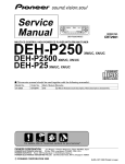
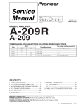
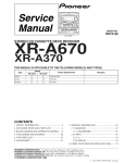
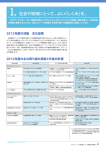
1
You can read the recommendations in the user guide, the technical guide or the installation guide for PIONEER A-207R. You'll find
the answers to all your questions on the PIONEER A-207R in the user manual (information, specifications, safety advice, size,
accessories, etc.). Detailed instructions for use are in the User's Guide.
User manual PIONEER A-207R
User guide PIONEER A-207R
Operating instructions PIONEER A-207R
Instructions for use PIONEER A-207R
Instruction manual PIONEER A-207R
You're reading an excerpt. Click here to read official PIONEER
A-207R user guide
http://yourpdfguides.com/dref/307835
Manual abstract:
+ + MIN MAX L R RRV1912 The illustration shows the A-307R. A-307R A-207R Type MYXJ/EW MYXJ/GR MVXJ SAMXJ SDXJ STEREO AMPLIFIER
THIS MANUAL IS APPLICABLE TO THE FOLLOWING MODEL(S) AND TYPE(S). Model A-307R A-207R Power Requirement AC220-230V AC220-230V
AC220-230V AC110V/120-127V/220V/240V AC110V/120-127V/220V/240V The voltage can be converted by the following method. With the voltage
selector With the voltage selector CONTENTS 1. SAFETY INFORMATION ......
.....
.....
..........
..........
.. 2 2. EXPLODED VIEWS AND PARTS LIST ..
.....
......... 3 3.
SCHEMATIC DIAGRAM ..........
.....
.....
..........
......... 6 4.
PCB CONNECTION DIAGRAM .....
.....
..........
...... 14 5. PCB PARTS LIST ...
.....
.....
..........
..........
.....
.....
.... 22 6. ADJUSTMENT .....
..........
.....
.....
..........
..........
.....
.. 25 PIONEER ELECTRONIC CORPORATION 7. GENERAL INFORMATION ..
..........
..........
.....
.....
26 7.1 IC .........
..........
.....
.....
..........
..........
.....
.....
...... 26 7.2 DISASSEMBLY ...
..........
.....
.....
..........
..........
27 7.3 BLOCK DIAGRAM ....
.....
..........
..........
.....
.....
28 8. PANEL FACILITIES AND SPECIFICATIONS .... 29 4-1, Meguro 1-Chome, Meguro-ku, Tokyo 153-8654, Japan PIONEER ELECTRONICS SERVICE,
INC. P.O. Box 1760, Long Beach, CA 90801-1760, U.S.
A. PIONEER ELECTRONIC (EUROPE) N.V. Haven 1087, Keetberglaan 1, 9120 Melsele, Belgium PIONEER ELECTRONICS ASIACENTRE PTE. LTD. 501
Orchard Road, #10-00 Lane Crawford Place, Singapore 0923 c PIONEER ELECTRONIC CORPORATION 1998 T - IZK APR. 1998 Printed in Japan
A-307R, A-207R 1. SAFETY INFORMATION This service manual is intended for qualified service technicians ; it is not meant for the casual do-ityourselfer.
Qualified technicians have the necessary test equipment and tools, and have been trained to properly and safely repair complex products such as those
covered by this manual. Improperly performed repairs can adversely affect the safety and reliability of the product and may void the warranty.
If you are not qualified to perform the repair of this product properly and safely, you should not risk trying to do so and refer the repair to a qualified service
technician. WARNING Lead in solder used in this product is listed by the California Health and Welfare agency as a known reproductive toxicant which may
cause birth defects or other reproductive harm (California Health & Safety Code, Section 25249.5). When servicing or handling circuit boards and other
components which contain lead in solder, avoid unprotected skin contact with the solder. @@@@@@Any current measured must not exceed 0.
5mA. 2. @@These are often not evident from visual inspection nor the protection afforded by them necessarily can be obtained by using replacement
components rated for voltage, wattage, etc. Replacement parts which have these special safety characteristics are identified in this Service Manual.
@@@@Product Safety is continuously under review and new instructions are issued from time to time.
For the latest information, always consult the current PIONEER Service Manual. A subscription to, or additional copies of, PIONEER Service Manual may be
obtained at a nominal charge from PIONEER. Device under test Test all exposed metal surfaces Reading should Leakage not be above current 0.5mA tester
Also test with plug reversed (Using AC adapter plug as required) Earth ground AC Leakage Test 2 A-307R, A-207R 2. EXPLODED VIEWS AND PARTS
LIST NOTES: · Parts marked by "NSP" are generally unavailable because they are not in our Master Spare Parts List. · The mark found on some component
parts indicates the importance of the safety factor of the part. Therefore, when replacing, be sure to use parts of identical designation. · Screws adjacent to
mark on the product are used for disassembly. (1) PACKING PARTS LIST Except MVXJ type 18 5 15 (SAMXJ type Only) 7 1 (Except MYXJ/GR type) 2
(MYXJ/EW and MYXJ/GR types Only) 13 3 (MYXJ/EW type Only) 4 (MYXJ/EW, MYXJ/GR and MVXJ types Only) 14 (SAMXJ type Only) 21 (SDXJ type
Only) 9 NSP NSP 2.1 PACKING MVXJ type Only 19 20 17 Mark No.
1 Description Part No. 12 6 Operating Instructions See Contrast table(2) (English) 2 Operating Instructions See Contrast table(2) (German) 3 Operating
Instructions See Contrast table(2) (French/Italian/Dutch/Swedish/Spanish/Portugese) 4 5 6 7 8 9 10 11 12 13 14 15 16 17 18 19 20 21 Warranty Card Remote
Control Unit (CU-A014) Battery Cover Dry Cell Battery (R6P,AA) Side Pad L Side Pad R Sub Pad Packing Case Literature Bag Packing Sheet Operating
Instructions (Chinese) Caution Label 220V Case Label Air Cap Power Cord Power Cord with Fuse Fuse (T5A) Operating Instructions (Spanish/Chinese) See
Contrast table(2) AXD7163 AZN2249 VEM-013 AHA7205 AHA7206 AHA7218 See Contrast table(2) AHG1180 AHG7015 See Contrast table(2) See Contrast
table(2) See Contrast table(2) See Contrast table(2) See Contrast table(2) See Contrast table(2) See Contrast table(2) See Contrast table(2) 8 10 FR ON NSP
T NSP 11 16 (SAMXJ type Only) (2) CONTRAST TABLE A-307R/MYXJ/EW, MYXJ/GR, SAMXJ, SDXJ, A-207R/MYXJ/EW, MYXJ/GR and MVXJ are
constructed the same except for the following : Part No. Mark No. @@@@@@Description Part No. Mark No. Description Part No. 5. @@·,C308
C321-C324 C173 C330,C332 C165,C166 C111-C113,C171,C341 C472 C159,C160 C161,C162 (2) PARTS LIST FOR AWX7119 SEMICONDUCTORS
IC454 (1A) IC453 IC451 IC452 IC101 IC301 IC151 Q311,Q312,Q329,Q330 Q337,Q338 Q313,Q314,Q321,Q322 Q452 Q309,Q310,Q327,Q328 Q339,Q340
Q315,Q316,Q319,Q320 Q303,Q304 Q451 Q341 Q101-Q104 Q151 Q152 Q153 Q331,Q332,Q343 Q333-Q336 Q317,Q318 Q323,Q324 Q325,Q326
D101-D104,D151,D301-D310 D401-D404 D451 D452-D455,D459,D460 D461 D311,D312 D457,D458 D456 D341 D462 AEK7009 BA178M06T
BA178M15T NJM79M15FA TC9163AN UPC4570C UPC4570G2 2SA1162 2SA1162 2SA1255 2SA1837 2SC2712 2SC2712 2SC3138 2SC3326 2SC4793
2SC5174P 2SK303 DTA124EK DTC124EK DTC124ES DTC143EK DTC143ES IMX1 IRF530 IRF9530 1SS355 1SS355 D5SBA20 S5566G(TPB2)
S5566G(TPB2) UDZ15B UDZ36B UDZ4.7B UDZS5.1B UDZS5.
6B RESISTORS R311,R312 R301,R302 R303,R304 R143 R133,R134,R171,R172 R351-R354,R452 R317,R318,R331,R332 R357-R360 R377,R378,R453
R465-R470 R361-R366 R339-R346 R454 R460 R355,R356 R459 R464 R379,R380 R451 R401,R402 R461-R463 R403 R373-R376 VR301,VR302 (2.2k) Other
Resistors RDR1/4VM152J RDR1/4VM240J RDR1/4VM561J RS1/10S100J RS1/10S101J RS1/10S101J RS1/10S122J RS1/10S151J RS1/10S153J RS1/10S161J
RS1/10S1R5J RS1/10S221J RS1/10S273J RS1/10S2R2J RS1/10S432J RS1/10S470J RS1/10S4R7J RS1/10S682J RS1LMF270J RS1LMF331J RS1LMF390J
RS1LMF821J RS1LMFR22J VCP1123 RS1/10S J COILS L151-L154 LCTA221J3225 RELAYS RY401-RY403 ASR7014 23 A-307R, A-207R Mark No.
@@@@Don't touch them or you will be electric shocked. 1. 2.
3. 4. 5. Connect the measuring instrument as shown in Fig.6-1.
(R373 or R374) Turn the POWER switch to ON. @@Ages for 5 minutes. Adjust VR301 (VR302) so that the voltage between both sides of R373 (R374)
becomes 11mV ± 1mV. DC Voltmeter DC Voltmeter AF ASSY SIDE A R373 R375 R374 R376 Heat Sink Heat Sink VR301 VR302 Heat Sink Heat Sink CN202
Fig.6-1 Adjustment Method 25 A-307R, A-207R 7. @@Pin name I/O Function 1 P53 I Remote control signal input pin.
You're reading an excerpt. Click here to read official PIONEER
A-207R user guide
http://yourpdfguides.com/dref/307835
2 O STB for TC9163N. P17/SRDY 3 P16/CLK O CLOCK for TC9163N. 4 P15/SOUT O DATA for TC9163N. 5 P14/SIN O CD INDICATOR.
6 P13/T1 O TUNER INDICATOR. 7 P12/T0 O PHONO INDICATOR. 8 P11 O LINE INDICATOR. 9 P10 O TAPE1 INDICATOR. 10 P27/IN7 O SPEAKER-A
INDICATOR. 11 P26/IN6 O SPEAKER-B INDICATOR. 12 P25/IN5 O LOUDNESS INDICATOR. 13 P24/IN4 O Not used. 14 P23/IN3 O Not used. 15
P22/IN2 O DIRECT INDICATOR.
16 P21/IN1 O TAPE2 INDICATOR. 17 P20/IN0 O FUNCTION switch MUTE. 18 VREF I Pulls up to 5V. 19 XIN I 4.19MHz .
20 XOUT O Ceramic vibrating and connecting terminal. 21 VSS - Digatal GND. 22 VCC - Power supply +5V. 23 P50/XCIN I SPEAKER-B KEY input. No.
Pin name I/O Function 24 P51/XCOUT I SPEAKER-A KEY input. 25 I Reset pin. RESET 26 P30/INT0 I BACK UP detection pin. interrupt specification. 27
P31/INT1 I Not used. 28 P32/CNTR0 I REC selector input 1. 29 P33/CNTR1 I REC selector input 2. interrupt specification. 30 P40 O Volume DOWN data
output. 31 P41 O Volume UP data output.
32 P42 I FUNCTION selector input 1. 33 P43 I FUNCTION selector input 2. WAKE UP input. I 34 P00 Key on wake up specification. 35 P01 O Not used.
DIRECT KEY input. I 36 P02 Key on wake up specification. 37 P03 O Protection control pin. 38 P04 I Output error detection pin 39 P05 O MUTING control
pin. LOUDNESS KEY input.
I 40 P06 Key on wake up specification. 41 P07 O Not used. @@@@@@@@@@@@@@@@@@@@Turning the knob clockwise causes the lit indicator
to right. Turning counterclockwise causes it to left. CD : For compact disc playback with a CD player.
TUNER : For AM or FM broadcast reception with a tuner. PHONO : For record playback with a turntable. @@@@Adjust balance if the sound is louder
from one of the speakers. @@@@@@@@The center position is the flat (normal) position. @@ON : The indicator lights.
Sound is heard from the speaker system. OFF : The indicator goes off. No sound is heard from the speaker system. @@@@@@@@The center position is
the flat (normal) position. When turned to the right, highfrequency tones are emphasized; when turned to the left, highfrequency tones are de-emphasized. ~
SPEAKERS A (ON/OFF) button/indicator Use this button to listen to the speaker system connected to SPEAKERS A terminals. ON : The indicator lights.
Sound is heard from the speaker system. OFF : The indicator goes off. No sound is heard from the speaker system.
Set to this position when listening with headphones. NOTE: This control does not operate when the DIRECT button is in the on position. 31 A-307R, A-207R
REMOTE CONTROL STANDBY/ON CD TUNER TAPE TAPE SELECT DECK DECK TAPE CD DISC SELECT STATION + TUNER CD TUNER PHONO +
VOLUME TAPE 1 TAPE 2 LINE STEREO AMPLIFIER REMOTE CONTROL UNIT 1 CD POWER button Switches CD player power STANDBY/ON. 7
TUNER POWER button Switches TUNER power STANDBY/ON. 2 TAPE SELECT button Selects the cassette No. (1 to 6) for multi-cassette changer. 8 TAPE
POWER button Switches the cassette deck power STANDBY/ON. (Can not turn ON/OFF some cassette decks.) 3 DECK II button To operate Deck II, press
this button before pressing the operating buttons. Also, when using a single deck, press this button before pressing the operating buttons.
9 TAPE operation buttons 2, 3 : Playback in the direction of the arrows. 7 : Stop 1, ¡ : Tape fast forward/reverse. 4 DECK I button To operate Deck I, press
this button before pressing the operating buttons. 0 CD player operation buttons 4 ¢ 7 3 : Returns you to the start of the current track. (Track search) : Takes
you to the start of the next track.
(Track search) : Stop : Play 5 DISC SELECT button Press this to select discs on a multi or twin tray compact disc player. 6 Input selector button Use to select
the playback source. CD : For compact disc playback with a CD player. TUNER : For AM or FM broadcast reception with a tuner. PHONO : For record
playback with a turntable.
TAPE 1 : For playback with a cassette deck or MD deck recorder connected to TAPE 1/MD terminals. TAPE 2 : For playback with a cassette deck or adaptor
connected to TAPE 2 MONITOR terminals. LINE : For playback with a component connected to the LINE terminal. - STATION + (up), (down) buttons Calls
each station number in sequence. = VOLUME + (up), (down) buttons + ......
..........
.....
.....
..........
..........
.....
.....
Increases the volume. .........
..........
.....
.....
..........
..........
.....
Decreases the volume. NOTE: When the accessory remote control unit is used to operate other Pioneer components with the Î mark, it cannot be used to
operate functions which do not correspond to the functions listed on the remote control unit. 32 A-307R, A-207R 8.2 SPECIFICATIONS Amplifier Section
Continuous power output (both channels driven at 20 Hz to 20 kHz) [A-307R] T.H.
D. 0.1 %, 8 ........
..........
.....
.....
......... 45 W + 45 W T.
H.D. 0.15 %, 4 .......
.....
.....
..........
........ 65 W + 65 W [A-207R] T.H.
D. 0.1 %, 8 ...
.....
..........
..........
.....
.... 35 W + 35 W T.
H.D. 0.15 %, 4 .......
..........
.....
.....
........ @@1.0 %, 8 .
..........
.....
.....
..........
....... 55 W + 55 W T.H.D.
1.0 %, 4 ....
.....
..........
..........
.....
.... 80 W + 80 W [A-207R] T.
H.D. 1.0 %, 8 .......
..........
.....
.....
..........
. 45 W + 45 W T.H.D. 1.0 %, 4 .....
.....
.....
..........
..........
... @@@@@@@@@@200 mV/50 k PHONO (MM) overload level 1 kHz, T.H.
D. 0.1 % ...
..........
..........
.....
.....
..........
. 150 mV Output level/impedance TAPE 1 REC, TAPE 2 MONITOR REC ..... 200 mV/1 k Frequency response PHONO (MM) ....
.....
.....
..........
. @@5 Hz to 100 kHz, +0 dB 3 Tone control BASS .........
.....
.....
..........
..........
.....
.....
...... ±8 dB (100 Hz) TREBLE ....
..........
.....
.....
..........
..........
.....
.. ±8 dB (10 kHz) Loudness contour (volume control set at 30 dB position) ...
..........
..........
.....
.....
....... +6 dB (100 Hz)/+4 dB (10 kHz) Signal-to-Noise ratio (IHF short circuit, A network) PHONO (MM, 5 mV input) ...
..........
.....
.....
..........
.. 85 dB CD, TUNER, LINE, TAPE 1/MD, TAPE 2 MONITOR ........
.....
.....
..........
..........
.....
.....
..........
..........
.....
... 106 dB Signal-to-Noise ratio (DIN, continuous power/50 mW) PHONO (MM) ..
..........
..........
.....
.....
..........
... @@@@AC 220 230 V, 50/60 Hz Power consumption [A-307R] .......
.....
.....
..........
..........
.....
.....
..........
....... 140 W [A-207R] ...
.....
.....
..........
..........
.....
.....
..........
..........
. @@@@@@@@1 Batteries (AA/R6P) ....
.....
..........
..........
.....
.....
..........
..........
... 2 Power cord (Rated current 2.5 A) .
.....
..........
..........
.....
.....
... 1 Operating instructions .......
..........
.....
.....
..........
..........
.....
.....
1 Warranty card ..........
..........
.....
.....
..........
..........
.....
.....
......... 1 NOTE: Specifications and design are subject to possible modifications without notice, due to improvements.
Measured with DIRECT button set to on. Measured by Audio Spectrum Analyzer. 33 .
You're reading an excerpt. Click here to read official PIONEER
A-207R user guide
http://yourpdfguides.com/dref/307835
Powered by TCPDF (www.tcpdf.org)