1
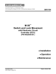
1000 Technology Drive, Pittsburgh, PA 15219 645 Russell Street, Batesburg, SC 29006 , PN-250F SM 9080 Relay Plug-In Replacement for the PF256 Flasher Relay ASTS USA Part No. N40116101 Installation Operation Maintenance © Copyright 2011 Ansaldo STS USA, Inc. SM 9080, Rev. 1 July 2011 Notices Proprietary Notice This document and its contents are the property of Ansaldo STS USA, Inc. (formerly known as Union Switch & Signal Inc., and hereinafter referred to as "ASTS USA"). This document is furnished to you on the following conditions: 1.) That no proprietary or intellectual property right or interest of ASTS USA is given or waived in supplying this document and its contents to you; and, 2.) That this document and its contents are not to be used or treated in any manner inconsistent with the rights of ASTS USA, or to its detriment, and are not to be copied, reproduced, disclosed or transferred to others, or improperly disposed of without the prior written consent of ASTS USA. Important Notice ASTS USA constantly strives to improve our products and keep our customers apprised of changes in technology. Following the recommendations contained in the attached service manual will provide our customers with optimum operational reliability. The data contained herein purports solely to describe the product, and does not create any warranties. Within the scope of the attached manual, it is impossible to take into account every eventuality that may arise with technical equipment in service. Please consult an ASTS USA local sales representative in the event of any irregularities with our product. ASTS USA expressly disclaims liability resulting from any improper handling or use of our equipment, even if these instructions contain no specific indication in this respect. We strongly recommend that only approved ASTS USA spare parts are used as replacements. SM 9080, Rev. 1, July 2011 i Revision History Revision History REV. DATE Original May 2003 1 July 2011 NATURE OF REVISION Initial Issue Revised Sections 3.2.2.1, 3.2.2.2, 3.2.2.3, 4.6.2, 4.6.3.1, 4.6.3.2, and 4.7.1. Copyright© 2011, Ansaldo STS USA, Inc. 1000 Technology Drive, Pittsburgh, PA USA 15219-3120 645 Russell Street, Batesburg, SC 29006 www.ansaldo-sts.com All rights reserved. ii SM 9080, Rev. 1, July 2011 Table of Contents Table of Contents 1. 2. 3. 4. GENERAL INFORMATION ............................................................................................................... 1-1 1.1. Introduction ............................................................................................................................... 1-1 1.2. Description ................................................................................................................................ 1-2 1.2.1. Coils .............................................................................................................................. 1-2 1.2.2. Contacts ........................................................................................................................ 1-2 1.3.1. Electrical ....................................................................................................................... 1-2 1.3.2. Mechanical .................................................................................................................... 1-3 INSTALLATION AND OPERATION ................................................................................................. 2-1 2.1. General ..................................................................................................................................... 2-1 2.2. Mounting Base .......................................................................................................................... 2-2 2.3. Flash Rate................................................................................................................................. 2-2 2.4. Electrical ................................................................................................................................... 2-2 2.5. Indexing .................................................................................................................................... 2-2 2.6. Receptacle Contact Springs ..................................................................................................... 2-2 2.6.1. Old Style Base Only ...................................................................................................... 2-2 2.6.2. Improved One-Piece Base Only ................................................................................... 2-3 2.6.3. Installing Wires in Receptacle Contact Springs ............................................................ 2-3 2.7. Relay Insertion .......................................................................................................................... 2-5 2.8. External Wiring ......................................................................................................................... 2-5 FIElD MAINTENANCE ...................................................................................................................... 3-1 3.1. Introduction ............................................................................................................................... 3-1 3.2. Periodic Performance Test ....................................................................................................... 3-1 3.2.1. Cleaning ........................................................................................................................ 3-1 3.2.2. Service Requirements .................................................................................................. 3-1 SHOP MAINTENANCE ..................................................................................................................... 4-1 4.1. Introduction ............................................................................................................................... 4-1 4.2. Cleaning and Inspection ........................................................................................................... 4-1 4.2.1. Cleaning Relay Contacts .............................................................................................. 4-2 4.2.2. Contacts With Surface Film or Oxidation (Not Pitted) .................................................. 4-2 4.3. Check-Out Procedure (Performance Test) ............................................................................... 4-2 4.4. Repairs and Replacement ........................................................................................................ 4-3 4.4.1. Disassembly.................................................................................................................. 4-3 4.4.2. Reassembly .................................................................................................................. 4-3 4.4.3. General Parts Replacement ......................................................................................... 4-3 4.5. Adjustments .............................................................................................................................. 4-4 4.5.1. Recommended Tools and Test Equipment .................................................................. 4-4 4.5.2. Magnet and Magnet Extension ..................................................................................... 4-4 4.5.3. Contact Adjustments on Relays With One Piece Molded Driver and New Contact Blocks Applied by Customers ....................................................................................... 4-5 4.5.4. Contact Adjustment, Old Blocks ................................................................................... 4-6 4.5.5. Hold-Down Force .......................................................................................................... 4-6 SM 9080, Rev. 1, July 2011 iii Table of Contents 5. 6. 4.6. Calibration ................................................................................................................................. 4-6 4.6.1. Recommended Test Equipment ................................................................................... 4-6 4.6.2. Calibration Procedure ................................................................................................... 4-6 4.6.3. Flash Rate Test (Relay with Flasher Module) .............................................................. 4-8 4.7. Calibration Requirements ......................................................................................................... 4-8 4.7.1. Calibration Values ......................................................................................................... 4-8 4.8. Contact Resistance ................................................................................................................... 4-9 PARTS LIST ...................................................................................................................................... 5-1 RAIL TEAM AND TECHNICAL SUPPORT ...................................................................................... 6-1 List of Figures Figure 1-1. PN-250F Relay................................................................................................................. 1-1 Figure 2-1. Relay Base showing Wiring Terminations ....................................................................... 2-1 Figure 2-2. New Mounting Base for PN-250F Relays ........................................................................ 2-4 Figure 2-3. Receptacle Spring Installed ............................................................................................. 2-5 Figure 4-1. Assembly of Permanent Magnet and Adjustment of Armature Position Indicator ........... 4-1 Figure 4-2. Heel Contact Springs ....................................................................................................... 4-5 Figure 4-3. PN-250F Relay Test Circuit ............................................................................................. 4-7 Figure 4-4. Flasher Relay Test Circuit ................................................................................................ 4-9 Figure 5-1. PN-250F Relay with One-Piece Molded Base ................................................................. 5-3 List of Tables Table 1-1. Electrical Specifications ................................................................................................... 1-2 Table 2-1. Base/Wire Combinations ................................................................................................. 2-4 Table 4-2. Recommended Test Equipment for Calibration ............................................................... 4-6 Table 4-3. Recommended Test Equipment for the Flasher Test ...................................................... 4-8 Table 4-4. Mechanical Adjustments and Hold-Down Torque ............................................................ 4-9 Table 4-5. Calibration Values - Single Coil Relays ........................................................................... 4-9 Table 5-1. Parts List for PN-250F Relay ........................................................................................... 5-1 iv SM 9080, Rev. 1, July 2011 General Information 1. GENERAL INFORMATION 1.1. Introduction This manual provides installation and operation information for the PN-250F plug-in DC Flasher Relay which is used as a flasher in signal systems. The PN-250F relay (N40116101) (Figure 1-1) was developed as a plug-in replacement for ASTS USA's PF-256 relay (N322561-XXX). The new PF-250F relay combines a solid state flasher with electromechanical relay contacts to provide a flexible, reliable relay to control the flashing of signals. As a plug-in replacement for the PF-256 relay, except for the flasher frequency selection described in Section 2.3, no wiring or system changes are required to exchange the relays. Figure 1-1. PN-250F Relay SM 9080, Rev. 1, July 2011 1-1 General Information 1.2. Description The PN-250F relay is an electronically driven, biased DC relay intended for use in signal flasher service. It uses an electronic flasher module to operate the relay at a selectable flash rate of 45 or 60 flashes per minute. Because the flash rate is electronically controlled, the rate is constant and is no longer dependent on mechanical adjustments. The electronic flasher package is mounted internally and is externally adjustable to provide 45 or 60 flashes per minute. The contact combination is 4NR silver alloy. The armature assembly in the PN-250F is hinged, eliminating the pivot screws and the wear associated with the pivots used in the PF-256. This results in a more reliable unit with longer service life. 1.2.1. Coils The PN-250F relay has a coil resistance of 87.5 ohms. 1.2.2. Contacts The four normal and four reverse contacts are silver alloy to silver alloy rated at 5 amperes at 30V dc or 175V ac. 1.3. Specifications The following paragraphs provide the electrical and mechanical specifications for the PN-250F relay. 1.3.1. Electrical The electrical specifications for the PN-250F relay are presented in Table 1-1. Table 1-1. Electrical Specifications Part No. Contacts System Power Flash Rate N401161-01 4 FB 10 – 14V dc @ 0.2 amp 45 or 60 +5 flashes/minute Contacts - silver alloy to silver alloy front and back rated at 5A at 30V dc or 175V ac. Power - DC power may be from battery or rectified DC current. 1-2 SM 9080, Rev. 1, July 2011 General Information 1.3.2. Mechanical All PN-250F relays have the following mechanical specifications. Dimensions Height Width Depth 7-1/16" (17.93 cm) 4 15/16” (12.64 cm) 8-3/8" (21.44 cm) Operating Temperature Range -40°F (-40°C) to +185°F (85°C) Indexing Refer to Section 2.5 Weight 6-3/4 lbs. Mounting Base - One-Piece Style (N438689-001). Weight - 9.5 oz. Dimensions Height 7-15/16" (20.16 cm) Width 4 15/16” (12.64 cm) Depth 1-25/32" (4.52 cm) Coil Resistance 87.5 ohms SM 9080, Rev. 1, July 2011 1-3 General Information 1-4 SM 9080, Rev. 1, July 2011 Installation and Operation 2. INSTALLATION AND OPERATION 2.1. General WARNING To avoid personal injury or equipment damage, observe all electrical safety precautions when installing the PN-250F relay. Power does not have to be turned off to insert the PN-250F into the existing base. As stated, the PN-250F relay is a plug-in replacement for the PF-256 relay. The relay base wiring is exactly the same as the PF-256 so no wiring changes are necessary (except for flash rate selection). The wiring terminations for the old style Bakelite base terminal are +A(+) and – A(-). The new style base terminal designations are 1A(+) and 1F(-). See Figure 2-1. DIRECT CONNECTION TO COIL FOR READING CALIBRATION VALUES IN THE FIELD -BATTERY +BATTERY 1 2 FLASH RATE SELECTOR JUMPER (INSTALLED FOR A 45 fpm FLASH RATE) 7 8 9 10 4N 3N 2N 1N 11 4H 3H 2H 1H 12 4R 3R 2R 1R Figure 2-1. Relay Base showing Wiring Terminations SM 9080, Rev. 1, July 2011 2-1 Installation and Maintenance 2.2. Mounting Base The mounting base is secured directly to the rack. All wiring terminates at the rear of the mounting base to solderless receptacle contact springs. The flash rate is selected as described in Section 2.3. Mounting base details are shown in Figure 5-1. 2.3. Flash Rate The flash rate is selectable for either 45 or 60 flashes per minute. The relay, when plugged into an existing PF-256 circuit, will flash at 60 flashes per minute. The rate can be easily changed to 45 flashes per minute by installing a jumper on the rear of the existing relay base. Two 7-inch jumpers are included with each relay. One jumper will be terminated with old style receptacles and the other will be terminated with new style receptacles. The type of relay base installed, old style Bakelite (N384243) or new style (M438689-001), will determine which jumper to use. The jumper for the old style base is installed between +B and -B and the new style base would between 2A and 2F. Without the jumper, the flash rate is 60 flashes per minute. 2.4. Electrical The PN-250F relay coil has ordinary pick up and drop away values as any standard biased relay. To check the electrical calibration values there is a connection that bypasses the internal flasher module so the electrical values can be checked. This is the T+ terminal on the old style base and 1B on the new style base. See for calibration values. 3.2.2.2, 3.2.2.2, The optimum on-time rate for the PN-250F is calibrated at 12 V DC. 2.5. Indexing The PN-250F is indexed so that it will replace either the PF-256 (N322561-001) or the PF-256 (N322561-002). The relay is factory equipped with indexing pins to prevent insertion of an incorrect relay into a mounting base. The relay is indexed so that it will plug into the current position of the N322561001 or N322561-002. 2.6. Receptacle Contact Springs 2.6.1. Old Style Base Only The old style mounting base was normally equipped with the required quantity of J680165 solderless receptacle contact springs, and would accommodate one or two #14 or #16 wires. It could, however, be equipped with receptacle contact springs for one or two #10 or #12 wires (J680181), or for one or two #18 or #20 wires (J680179). 2-2 SM 9080, Rev. 1, July 2011 Installation and Operation Make certain which type of solderless receptacle contact springs accompany the mounting base before proceeding with their installation. 2.6.2. Improved One-Piece Base Only The one-piece mounting base (Figure 2-2) with hardware (N438689-001) includes a full complement of receptacle contact springs (M451142-2702) to accommodate one or two #14-#16 wires mounting fasteners and tags. It can, however, be equipped with receptacle contact springs for one or two #18-#20 wires (M451142-2701), or for one or two #10 - #12 (M451142-2703) wires. Make certain which type of solderless receptacle contact springs accompany the mounting base before proceeding with their installation. Each solderless receptacle contact spring should be inspected for physical damage before proceeding with installation. The following is recommended when installing solderless receptacle contact springs: 1. Receptacle contact springs must be inserted into the base cavity with the lock side down (Figure 2-3). 2. Make certain that the lanced tab is slightly compressed when the receptacle contact spring is inserted along the top of the cavity. The lanced tab could have been bent during handling, and therefore might not provide the required contact pressure after the relay is inserted. If the lanced tab does not touch, pull it up slightly using fingers or a suitable tool. 3. After insertion, pull firmly on the wire to make certain the receptacle contact spring is locked in the cavity. 4. Have available the contact removal tools: J772383 – New Style (Yellow) J077931 – Old style (Red) 2.6.3. Installing Wires in Receptacle Contact Springs Use the following procedure to ensure a good electrical and mechanical connection between the conductor wire and the receptacle contact spring. Table 2-1 identifies the correct crimping tool to be used when installing wires in receptacle contact springs. 1. Strip 3/16 in. (0.187 in. or 0.47 cm.) of insulation from the end of the wire. 2. Place the receptacle contact spring into the jaws of the proper crimping tool. 3. Partially close the crimping tool jaws against the receptacle contact spring to hold it in place. (Do not crush the receptacle contact spring barrel at this time.) 4. Insert the stripped end of wire all the way into the receptacle contact spring barrel. Squeeze the tool handles until crimping is completed and the jaws release. Always attach the first wire to the longest terminal. This ensures that a second lead may be attached to the receptacle contact spring at a later time. SM 9080, Rev. 1, July 2011 2-3 Installation and Maintenance 5. Remove the crimped receptacle contact spring from the tool arid inspect the connection. Make certain that the wire is flush with the crimped barrel and that there are no loose strands of wire. Figure 2-2. New Mounting Base for PN-250F Relays Table 2-1. Base/Wire Combinations Crimping Tool (Amp Type) J397138 J397139 J397188 2-4 Wire Size #10/#12 AWG #14/#16 AWG #18/#20 AWG Old Style Receptacle J680181 J680165 (Std) J680179 Improved Base Receptacle Contact Spring M451142-2703 M451142-2702 M451142-2701 SM 9080, Rev. 1, July 2011 Installation and Operation 2.7. Relay Insertion Orient the relay to the mounting base with the push rod to the left-hand side; then plug the relay into the base. The relay should be pushed firmly against the mounting base while depressing the latch rod. After the relay is completely seated in the base, release the latch rod and pull on the handle to ensure that the relay has locked in place. 2.8. External Wiring The pin outs of the relay are the same as for the PF256 it replaces except for the flash rate selection jumper (see Figure 2-1). MOUNTING BASE WIRES RECEPTACLE SPRING CONTACT Figure 2-3. Receptacle Spring Installed SM 9080, Rev. 1, July 2011 2-5 Installation and Maintenance 2-6 SM 9080, Rev. 1, July 2011 Field Maintenance 3. FIElD MAINTENANCE 3.1. Introduction This section provides the necessary periodic preventive maintenance procedures which must be performed to ensure continuous, proper, and efficient operation of the PN-250F relay. Field maintenance covers periodic inspections and performance tests. 3.2. Periodic Performance Test 3.2.1. Cleaning Before inspecting and testing the relay, if necessary, use a soft cloth to clean the exterior to remove any dirt or dust that may have collected. A cleaning solution safe for use with plastics may be used for removal of accumulated dirt, grease, etc. 3.2.2. Service Requirements 3.2.2.1. General NOTE Maintenance shall be performed in accordance with railroad company guidelines. Minimum guidelines set forth in FRA CFR 49 Part 234.263 and Part 236.106 require the flasher relay to be inspected once upon installation and as follows: After not more than 10 million operations or 4 years, whichever occurs first, for a 45 flash rate relay (highway crossing lights flashing). After not more than 5 million operations or 4 years, whichever occurs first, for a 60 flash rate relay (wayside signal light flashing). The tests and inspections are to include flash rate and visual inspection of contacts for damage or misalignment, corrosion or other contamination of parts, loose parts inside of the cover, broken seal, and cracked or broken cover. The contact surfaces will normally roughen and appear burned due to service. The contacts should be examined for cratering or for material transfer which could result in mechanically interlocking the contacts. Relays having contacts with severely eroded surfaces, indicating more than the loss of 50% of the contact thickness, should be replaced. The flash rate is controlled by electronic package and is relatively independent of the relay’s calibration so it is not necessary to replace the electronics should the relay need be removed from service for repair. If the flash rate is outside the requirements or is severely unbalanced the electronic package must be replaced. Relays not passing tests and inspections must be replaced and not returned to service until the operating characteristics and conditions are in accordance with ASTS USA specifications. SM 9080, Rev. 1, July 2011 3-1 Field Maintenance 3.2.2.2. In-Service Visual Inspection When conducting a visual inspection at the intervals stated in Section 3.2.2.1, it is recommended that flasher relays be removed from service for shop repairs if one or more of the following conditions are observed: 1. The flash rate is not within ± 5 FPM of selected flash rate. (This does not indicate a complete failure; the relay can be left in service, if the flash rate is not objectionable.) 2. The on-time of the lamps becomes objectionably unbalanced. 3. If the contacts are worn to such a degree that failure is imminent. 3.2.2.3. Test Procedures If a flasher relay is removed from service based on the observation(s) stated in Section 3.2.2.2, additional testing may be conducted to confirm the need for sending the relay to the ASTS USA Service Shop for shop repairs. Measure the Drop Away, Full Drop Away and Full Stroke Pick Up current values using the procedure in Section 4.6.2. If the Drop Away current value falls below 67% of the value given in Table 4-5, or if the Full Drop Away current value falls below 33% of the value given in Table 4-5, or if the Full Stroke Pickup current is more than 110% of the value given in Table 4-5, the relay is considered to be out of calibration and needs shop maintenance. The flash rate and on-time values can be measured using the procedure given in Section 4.6.2. 3-2 SM 9080, Rev. 1, July 2011 Shop Maintenance 4. SHOP MAINTENANCE 4.1. Introduction This section provides the information necessary to perform shop level repairs on the PN-250F style relay. In general, relays arriving at the shop for repair have been checked in the field and have been found to perform unacceptably or have been physically damaged. 4.2. Cleaning and Inspection Before inspecting the relay and initiating repairs, use a soft cloth to clean the exterior carefully to remove any dirt or dust that may have collected. A safe cleaning solution or alcohol and water may be used for removal or accumulated dirt, grease, etc. Inspect the relay exterior for signs or physical damage, such as a cracked or broken cover, cracked or damaged housing, and damaged and/or missing contact block terminals and indexing pins. If severe damage is found, a careful inspection or the interior components should be made for obvious physical damage. Remove the cover and clean the surface between the armature and the pole races, especially the stop pin area (see Figure 4-1), using a lint free cloth and alcohol. Proceed with relay contact cleaning, using the recommended cleaning materials listed in Table 4-1. ADJUSTMENT SHUNT MAGNET MAGNETIC SHUNT STOP PIN POLE PIECE MAGNET EXTENSION PHOSPHOR BRONZE OR STEEL SCREW AS REQUIRED NOTCHES IN MAGNET Figure 4-1. Assembly of Permanent Magnet and Adjustment of Armature Position Indicator SM 9080, Rev. 1, July 2011 4-1 Shop Maintenance 4.2.1. Cleaning Relay Contacts After contacts have been dressed and/or after adjustments have been made to meet calibration requirements, the contacts should be cleaned in accordance with the procedures presented below. NOTE When using the paper strip, clean the back contacts first, then the front contacts last. Discard the paper strips when dirty. Table 4-1. Recommended Cleaning Materials Material/Part Number Burnishing Tool, P.K. Neuses Co. No. 3-316 J397187 Burnishing Tool, P.K. .Neuses Co. No. 3-318 (Heavy Duty) J397187-001 Paper Strip, 50 strips cut from 67# white Springhill Vellum Bristol Paper (or equivalent) J793094 Emery Paper, Wet or Dry, 600 grit, cut in strips (Commercially Available) Denatured Alcohol (Commercially Available) 4.2.1.1.1. Contacts That Are Severely Burned 1. Using a 600 grit emery paper strip folded with the grit side out so that both contacts can be burnished simultaneously, stroke the contacts in the direction of contact wipe. 2. Using the burnishing tool, stroke the contacts several times in the direction of contact wipe. 3. Place a paper strip between the open contacts, then close the contacts and withdraw the paper strip. 4. Repeat Step 3 several times if necessary. 5. Using denatured alcohol, give the contacts a degreasing wash. 6. Place a paper strip between the open contacts, then close the contacts and withdraw the paper strip. 7. Repeat Step 6 until the paper strip is clean after being withdrawn. 4.2.1.2. Contacts With Heavy Tarnish, Slightly Rough, or Pitted Perform Steps 2 through 7 of Section 4.2.1.1.1. 4.2.2. Contacts With Surface Film or Oxidation (Not Pitted) Perform Steps 6 and 7 of Section 4.2.1.1.1. 4.3. Check-Out Procedure (Performance Test) Test the calibration of the relay in accordance with Section 4.6. 4-2 SM 9080, Rev. 1, July 2011 Shop Maintenance 4.4. Repairs and Replacement Since the contacts are the only wearing parts in this relay, in most cases the relay can be restored to proper operation by dressing (Section 4.2.1) and readjusting them (Section 4.5.3 or 4.5.4 as applicable). 4.4.1. Disassembly Dismantle the relay only to the degree necessary to complete repairs. Refer to the Parts List (Appendix A) for part information and location of parts. In general, to dismantle the plug-in relay, proceed as follows: 1. Remove relay cover seal. 2. Carefully remove the plastic cover. 3. Remove/disassemble the relay components as required. 4. Remove contacts/contact block as required. 5. Remove the permanent magnet as required. NOTE These magnets are of a special alloy that permits retention of proper strength indefinitely if not abused. When not in place on relays, magnet assemblies should be kept separated from other magnetic objects, and the screws, which hold the extension to the magnet, should be kept tight. Should a magnet become weakened, it should be returned to the factory for recharging where there is special equipment required to fully charge the magnet, and then age it to its best working strength. 4.4.2. Reassembly Reassembly is accomplished generally in the reverse order of disassembly. The following paragraphs provide additional instructions to be followed during reassembly of the relay. 4.4.3. General Parts Replacement NOTE Do not over-tighten or force parts when reassembling the relay. Upon completion of reassembly, calibrate the relay per Section 4.6. 4.4.3.1. Replacing Contact Block 1. If the contact block is to be replaced, remove the old block, then use a small punch to remove the small dowel pins that secure the block. Attach the new block with the four screws. Run a #42 drill (0.0935 Dia.) through the dowel pin holes into the epoxy contact block for a total depth of 9/16" + 1/32 - 0. SM 9080, Rev. 1, July 2011 4-3 Shop Maintenance NOTE Replacement contact blocks MUST be of the same general design. 2. Carefully install the dowel pins, tapping in until they are flush with the aluminum surface. 3. If it is necessary to install a used contact block from another relay, remove only one of the dowel pins from the aluminum frame. Carefully press the block on the remaining pin and fasten in place with the screws. One dowel pin will adequately hold the block in place. 4. Do not over-tighten or force parts when reassembling a relay. Upon completion of reassembly, calibrate the relay as directed in paragraph 4.6. 4.4.3.2. Permanent Magnet The polarity of the magnet should be such that the top end farthest from the two notched holes will attract the end of a compass needle which points toward geographic South (see Figure 4-1). The permanent magnet assembly should be applied to the relay as shown in Figure 4-1 making sure that the shunt between the magnet and the magnet extension is touching the pole piece. Tighten the two long screws holding the magnet assembly to the pole piece sufficiently to straighten the curved strap against the magnet. Bend the nut locks securely up against the sides of the screw heads. 4.5. Adjustments NOTE All adjusting and testing must be done with the relay in its normal upright position. 4.5.1. Recommended Tools and Test Equipment Thickness Gauges - 0.001 in. to 0.200 in. Gram Gauge - 250 Grams Screw Driver - Torque Measuring 4.5.2. Magnet and Magnet Extension Insert a 0.130 inch spacer between the stop pin and the pole face and adjust the permanent magnet extension so that it touches the Teflon back stop tape or the back stop pins, whichever is present on the bottom of the armature. 4-4 SM 9080, Rev. 1, July 2011 Shop Maintenance After adjustment, the magnet and magnet extension should be centered on each other and on the armature. On relays without back stop pins, the bottom of the armature should fit flush on the surface of the magnet extension, with no air gaps. On relays with back stop pins, the air gap should be of uniform width across the surface of the magnet extension. 4.5.3. Contact Adjustments on Relays With One Piece Molded Driver and New Contact Blocks Applied by Customers The contact block or blocks should be installed in the relay frame with screws tightened by means of a torque measuring tool to 10 +/- 2 inch-pounds. The dowel pin hole or holes in the relay frame must be so located that the completed relay will fit freely into its proper mounting base (without receptacle contact springs). Proceed as follows to apply new contact locks: 1. Set all contact stops to be open. 2. With a 0.0153" spacer under the core pin, set all front contacts to be closed. All front contacts should open on a 0.058" spacer. 3. With a 0.077" spacer under the core pin, set all back contacts to be closed. All back contacts should be open on a 0.072" spacer. 4. Using Tool 1451151-2801, remove the driver and adjust the heel springs so that they are neither touching the front nor the back contacts. 5. Reinstall the driver and recheck the settings per Steps 2 and 3 above. 6. With a 0.042" spacer under the core pin, adjust the contact stops so that all front contacts are closed. With a 0.047" spacer, all fronts should be in their open positions. 7. With a 0.088" spacer under the core pin, adjust the back stops so that all backs are closed. With a 0.083” spacer all backs should be open. 8. Check that all Full Stroke Pick Up and Release that all stops are open. This opening should be approximately 0.008.” 9. With the armature held in the mid-point position, with neither fronts nor backs making, check to see that the free play between the heel spring and the driver is 0.010" or less. If the free play is excessive, adjust the height of the clip as shown in Figure 4-2. .100” .094” Figure 4-2. Heel Contact Springs SM 9080, Rev. 1, July 2011 4-5 Shop Maintenance 4.5.4. Contact Adjustment, Old Blocks For original factory installed blocks, adjust the contacts per Steps 6 and 7 of Section 4.5.3 above and check the stop opening per Step 8. If the 0.008” opening cannot be maintained, then complete contact adjustment must be performed. 4.5.5. Hold-Down Force With the relay in the normal upright position and deenergized, a force of at least 190 grams (Table 4-4) should be required to move the armature away from the permanent magnet assembly. This upward force should be measured with a gram gage at the bottom end of the centermost contact driver. The hold down force can be increased, if necessary, by bending the shunting strip (which is fastened to its forward face) away from the permanent magnet. If one or both of the two vertical screws which fasten the permanent magnet assembly to the relay frame is steel, a further increase in hold-down force can be obtained by changing to bronze screws. The steel screw, J463078, has dull (tin) plating and its head is 3/32 inch thick. The bronze screw, M327179, has brighter (nickel) plating and its head is 1/8 inch thick. Any change in the hold-down force will affect the relay calibration, as discussed in Sections 4.6 and 4.7. 4.6. Calibration The relay is calibrated with the flasher module bypassed. The flasher needs no calibration 4.6.1. Recommended Test Equipment The recommended test equipment is listed in Table 4-2. Table 4-2. Recommended Test Equipment for Calibration NOMENCLATURE/PART/MODEL/TYPE NO Power Supply, Variable, 0-40 Vdc Digital Multimeter (two required) Fluke Model 87 or equivalent DPDT (double pole, double throw-S1). SPST Switch (S2) 4.6.2. Calibration Procedure Proceed as follows to calibrate the relay: 1. Connect the circuit, as shown in Figure 4-3. 2. Set the voltmeter to the appropriate voltage range. 3. Set the ammeter to the appropriate current range. 4. Set switch S1 to its Normal position. 4-6 SM 9080, Rev. 1, July 2011 Shop Maintenance 5. Turn the dc power supply on, and close switch S2. 6. Observe the ammeter and adjust the dc power supply output control to obtain the charge current reading indicated in the Amps portion of the Charge column in Table 4-5. Note that the relay energizes and remains energized as the voltage increases. 7. Set switch S1 to its Reverse position. The relay should deenergize. 8. Set switch S1 to its Normal position. The relay should again energize. 9. Adjust the dc power supply output control to reduce the current at a rate so as not to overshoot the actual value and measure the Drop Away, which is the value at which the front contacts open (refer to Table 4-5 for the acceptable value). 10. Further reduce the dc power supply output control setting at a rate so as not to overshoot the actual value and check the minimum Drop Away with Full Back Contact Compression (refer to Table 4-5 for the acceptable value). Reduce the current to zero then open the circuit momentarily using switch S2. 11. Adjust the dc power supply output control to increase current at a rate so as not to overshoot the actual value, and obtain Pick Up, which is the value at which the front contacts make. (Refer to Table 4-5 for the acceptable value.) 12. Further increase the dc power supply output control at a rate so as not to overshoot the actual value to obtain the relay Full Stroke value, which is the value at which the armature is tight up to its stop pins. Frequently, Pick Up and Full Stroke will be the same value. AMMETER S2 A (TERMINAL 1B) + S1 + POWER SUPPLY _ VOLTMETER V NORMAL REVERSE RELAY UNDER TEST _ (TERMINAL 1F) Figure 4-3. PN-250F Relay Test Circuit SM 9080, Rev. 1, July 2011 4-7 Shop Maintenance 4.6.3. Flash Rate Test (Relay with Flasher Module) 4.6.3.1. Recommended Test Equipment The recommended test equipment for the flasher test is listed in Table 4-3. Table 4-3. Recommended Test Equipment for the Flasher Test NOMENCLATURE PART/MODEL/TYPE NO . Power Supply, Variable, 0-40 Vdc Digital Multimeter Fluke Model 87 or equivalent SPST Switch (S2) DPDT (single pole, single throw) Switch Counter: Redington R9-3206 or equivalent On-Time Meter PD-30 (Simpson-TS-111) 4.6.3.2. Procedure Connect the flasher relay test circuit, as shown in Figure 4-4, jumper terminals 2F and 2A on the back of the relay base, and proceed as follows: 1. Set M1 to appropriate DC voltage range. 2. Turn DC power supply on and adjust for 12 +/- 0.1V dc output. 3. Set switch S1 on the ON position and simultaneously begin to time a period of three minutes. 4. At the end of precisely three minutes, set switch S1 to OFF, and note the reading at the counter . 5. Divide the counter reading by three. The resultant rate should be 45 +/- 5 counts per minute. 6. Reset the counter to zero and remove the jumper from terminals 2F and 2A. 7. Repeat Steps 3 and 4. 8. Divide the counter reading by three. The resulting rate should be 60 +/- 5 counts per minute. 9. With switch S1 set to OFF and the relay operating at 12 volts, connect leads of the OnTime Meter across the heel and front contacts, and then across the heel and back contacts. The front and back contact on-time readings should be between 45 and 55%. 4.7. Calibration Requirements 4.7.1. Calibration Values Calibration requirements will be met when the relay adjustment values are the same as those given in Table 4-5. After any shop adjustments are made, check the calibration values (Section 4.6.2). If they are not within the values given in Table 4-5, the relay should not be shipped for in-service use. 4-8 SM 9080, Rev. 1, July 2011 Shop Maintenance S1 OFF NORMAL (UPPER CONTACT) H ON (HEEL) REVERSE (LOWER CONTACT) +A + + M1 POWER SUPPLY _ FLASHER UNDER TEST F V COUNTER _ _A Figure 4-4. Flasher Relay Test Circuit 4.8. Contact Resistance Resistance of front contacts should be measured with the armature in its full-stroke position, and resistance of back contacts should be measured with the armature fully released. Cleaned contact resistances should not exceed the following value. Silver Alloy to Silver Alloy 0.03 ohms Contact surfaces should not be disturbed unless there is evidence of severe pitting from excessive loading or an accidental short through the contacts. When contacts must be dressed, refer to Section 4.2.1 or 4.2.2. Table 4-4. Mechanical Adjustments and Hold-Down Torque Relay Arm. Air Gap (in.) Arm. Stroke (in.) Min Hold Down (Grams) PN-250F 0.0310 0.130 190 Adjusting Spacers Front Contacts Closed Open Rear Contacts Closed Open (in.) (in.) (in.) (in.) 0.042 0.047 0.088 0.083 Table 4-5. Calibration Values - Single Coil Relays Relay Style Ohms Charge (Amp) Min. Drop Away (Amp) Min Full Drop Away (Amp) Max Pick Up & Full Stroke (Amp) 250F 87.5 0.260 0.022 0.006 0.065 SM 9080, Rev. 1, July 2011 4-9 Shop Maintenance 4-10 SM 9080, Rev. 1, July 2011 Shop Maintenance 5. PARTS LIST Table 5-1 gives the parts tabulation for the PN-250F relay and Figure 1-1 shows the location of the parts. Table 5-1. Parts List for PN-250F Relay Item No. 01 02 03 04 05 06 07 08 09 10 11 12 13 14 15 16 17 19 20 21 22 23 24 25 26 27 28 29 30 31 32 33 34 35 36 37 38 39 40 41 42 43 44 45 46 47 Part Number M349197003 M349392 J770536 M395496 M321728 J048716 M321861 M436567 M435315 J046194 J487090 J522042 M434091 M434092 M433358 J026107 J052531 N438716 J5001320116 M434648 R349782 J525107 J052066 M321853 J463078 M327179 M168824 M68826 J776323 J5001310108 J792919 J525024 N188858 M349652 M4511380601 J050244 J776597 J047081 J7763070001 J5072950119 J561111 J4751210125 J5072360129 S002955 A043013 J079351 SM 9080, Rev. 1, July 2011 Part Description Frame Latch Rod, 1/8” Steel Knurled Knob, Nut Nut, 1/8” Heavy Latch, Machined Roll Pin, Stainless Steel Spring, Plated Plate, Mounting Hinge Plate Screw, 8 – 32 x 5/8” Hex Head Roll Pin – 3/32” D x 1-1/8” Screw, 8 – 32 x 7/16 Fil Head, Stainless Steel Shim, #40 B&S Gage Brass Shim, #28 x 3/8 Brass Shim, #24 x 6 Bronze Block, Hinge Aluminum Screw, 8 – 32 x ½” Round Head Contact Block Screw, 8 – 32 x 1” Round Head, Stainless Steel Spring Armature Pole, PC and Core Screw, 8 – 32 x ¾” Round Head Screw, 8 – 32 x 5/8” Fil Head Magnet Steel Strap Bolt, 8 – 32 x 1-1/4” Steel Screw, ¼” Hex Head, Bronze Rd Washer Washer Contact Block, Molded Screw, 8 – 32 x ½” Round Head Lock Bolt, Monel Screw, 4 – 40 x 3/16” Pan Head, Stainless Steel Coil Component Coil Lock Strap Screw, 10 – 32 x 3/8” Sch Relay Cover, Molded Rubber Gasket Relay Cover, Molded Screw, 8 – 32 x 7/16” Fh Pull Handle, Aluminum Washer, #10 Shake Proof, Stainless Steel Screw, 10 – 32 x 3/8” PH, Stainless Steel Tag Seal Wire, #23 x 12, Stainless Steel Lead Seal 5-1 Parts List Item No. 48 50 51 52 55 56 57 58 60 61 62 63 64 65 66 67 69 71* 72* Part Number J630943 J047714 PN435191 N4511370501 M385765 J790257 J7091460520 M349590 J475200109 J0481620002 J726274 J735547 J487087 M385766 M275388 M433346 J751247 N40116201 N40116202 Part Description Name Plate, Aluminum Washer #8, Lock, Shakeproof, Stainless Steel Permanent Magnet Armature Operating Arm Seal, Adhesive Ventil Faston Terminal, #16 – 14, 640905-1 Spring, #26, Phos Bronze, Round Washer, #8 Plate, Stainless Steel Nut, 8 - 32, Elastic Stop Relay Flasher Varis – 26 VDS V33ZA5 Roll Pin, 3/32” D x 3/8” Screw, ¼” Hex Head, Steel Lock Nut, 0.006 x 5/16”, Steel Spring Hinge Sponge Rubber seal Jumper for new improved base Jumper for old Bakelite base * Not shown in Figure 5-1 5-2 SM 9080, Rev. 1, July 2011 Shop Maintenance Figure 5-1. PN-250F Relay with One-Piece Molded Base SM 9080, Rev. 1, July 2011 5-3 Parts List 5-4 SM 9080, Rev. 1, July 2011 Technical Support 6. RAIL TEAM AND TECHNICAL SUPPORT The Rapid Action Information Link Team (RAIL Team) is a group of experienced product and application engineers ready to assist you to resolve any technical issues concerning this product. Contact the RAIL Team in the United States at 1-800-652-7276 or by e-mail at [email protected]. SM 9080, Rev. 1, July 2011 6-1 RAIL Team and Technical Support End of Manual 6-2 SM 9080, Rev. 1, July 2011