1
SERVICE MANUAL 4587
PN-150T TIME ELEMENT RELAY
WITH 2F CONTACTS
* * * * * * * * * * * * * *
CONTENTS
Page
Section
I
II
III
IV
v
VI
VII
VIII
IX
x
February, 1981
C-2/84-200-1271-1
PRINTED IN USA
GENERAL
2
DESCRIPTION
2
INSTALLATION AND SERVICE RECOMMENDATIONS
4
RELAY OPERATION
4
RELAY ADJUSTMENTS
5
DELAY UNIT DESCRIPTION AND TESTING
5
RELAY CALIBRATION
6
SERVICE TESTS
7/8
UPDATING THE 001 TO 007 AND 201 TO
207 SUFFIX SERIES RELAY 301 TO
307 SUFFIX SERIES RELAYS
11
PARTS LIST
15
UNION SWITCH & SIGNAL DIVISION
AMERICAN STANDARD INC./ SWISSVALE, PA 15218
ffi
UNION SWITCH & SIGNAL
I.
GENERAL
This manual is supplied as a guide for operation and maintenance of the PN-150T relay. The manual covers PN-150T relays
with suffix numbers of 001 to 007, 201 to 208, and 301 to
308. Table 1 lists the part numbers of the PN-150T's covered
by this manual and the corresponding voltage rating, and time
range of each.
TABLE 1
PN-150T RELAYS PART NUMBER, VOLTAGE, AND TIME RANGE
000 Series
N322523-001
N322523-002
N322523-003
N322523-004
N322523-005
N322523-006
N322523-007
200 Series
300-Series
N322523-201
N322523-202
N322523-203
N322523-204
N322523-205
N322523-206
N322523-207
N322523-208
N322523-301
N322523-302
N322523-303
N322523-304
N322523-305
N322523-306
N322523-307
N322523-308
Volts
10
12
16
10
12
16
10
12
Time Range
3-30 sec.
3-30 sec.
3-30 sec.
1/2-5 min.
1/2-5 min.
1/2-5 min.
1-10 min.
1-10 min.
Some of the 001 to 007 suffix series relays have "C" terminals
on the contact block. The 200 suffix series relays contain
redesigned electronic delay units. The 300 suffix series
relays contain delay units with improvements to further increase reliability, for greater reliability. Relays
N322523-803 and N322523-806 are physically equivalent to
N322523-203 and N322523-206 (respectively); but the former
have LEXAN* covers. All 300 suffix series relays have LEXAN*
covers.
II.
DESCRIPTION
The PN-150T relay is a DC, plug-in, time element relay, and
has two front or time contacts for external connection. It
is basically a PN-150B relay with an internal electronic
delay unit to determine the relay pick-up time. The PN-150T
relay is furnished for 10, 12, or 16 volt operation. The
pick-up time is adjustable from 3 to 30 seconds for the 30
second relay, .5 to 5 minutes for the 5 minute relay, and 1
to 10 minutes for the ten minute relay. The release time is
fixed at 0.5 second for all relays. The power consumption
varies from 0.5 watts to 2.5 watts depending on the input
voltage. The PN-150T has two standard silver heel contacts
and two silver impregnated carbon front contacts rated at 4
amps and up to 30 VDC or 175 VAC.
* Trademark of General Electric
4587, p. 2
UNION SWITCH & SIGNAL
TABLE II
TEST VALUES
Rated
Volts
Test Voltage
Low
High
10
12
16
8.5
10.0
13.0
Min. F.D.A.
Shop
Service
12.5
15.0
20.0
1.5
1.8
2.4
'"c"
1.0
1. 2
1. 6
TERMINAL*
,---- ------,---------,
I
I
I
TIME
2F CONTACTS lF I
~
.--:9 I
-~ ~ I
TIME
/
ADJUSTMENT
+u--1---i
TERMINALS
(FROM REAR
OF RELAY)
I
I
I
ZENER
REGULATOR
CIRCUIT
o
I
',
I
I
ui
I
-~-
/
TRANSISTOR
TRIGGER
DEVICE
TIMINGTOR
CAPAC!
S
;::;
~
~
~
I
I
I
I
L------------- ________ J
DELAY UNIT
RELAY STICK
COIL
CONTACT
*
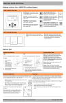
Used only on some 001-007 suffix series relays
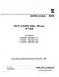
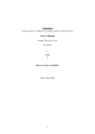
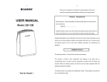
Figure 1.
Basic Circuit For All Suffix Series Relays
4587, p. 3
m
ffi
UNION SWITCH & SIGNAL
III.
INSTALLATION AND SERVICE RECOMMENDATIONS
The plastic indexing plate furnished with the relay should be
applied to the mounting base for the relay using the screws
provided. To adjust the time interval, remove the plug screw
from the front of the relay and turn the internal screw with
a small screwdriver. Clockwise rotation will increase the
time.
The 200 suffix and 300 suffix relays have a timing dial,
located on the front of the delay unit that indicates the
delay time; that is, the time starting at the application of
power to the relay's control circuit and ending with the heels
making contact with fronts. Accuracy of the timing dial is
+10%. Accurate time settings are made using a stop watch.
A red light on the front of the delay unit starts to glow
the moment power is applied to the relay's control circuit,
indicating the timing cycle has started. Closure between
front and heel contacts indicates the end of the timing cycle.
The red indicator light will continue to glow after closure
on front contacts, and will only be extinguished when power
is removed from the relay's control circuit.
It is recommended that the relay be checked at regular
intervals for proper pick-up time, and at longer intervals
to meet the requirements given in Section VIII.
The 200 suffix and 300 suffix series relays will operate from
85% to 125% of rated voltage. The suffix 000 series relays
can be energized at up to 150% of rated voltage. Voltages
in excess of these amounts should be avoided as they cause
excessive power dissipation that can damage the components
within the delay units.
IV.
RELAY OPERATION
The basic circuit for all suffix series relays is shown in
Figure 1. Constant voltage of the zener regulator charges
a solid tantalum capacitor bank through an adjustable resistor
the charging time being proportional to the resistance setting.
When the capacitors have charged to a reference voltage
determined by the divider resistors, a transistor combination
is triggered, causing the capacitors to discharge through the
relay coil. A resulting pulse picks up the relay which holds
itself up over an internal front stick contact until the
supply voltage is removed.
4587, p. 4
UNION SWITCH & SIGNAL
V.
RELAY ADJUSTMENTS
The relay armature is set at the factory to a parallel air
gap of 0.23 inch. The adjustable back stop screw in the
horizontal extension of the permanent magnet assembly is
adjusted to provide an air gap of .016 inch between the
armature and the extension. The extension itself is adjusted
to provide an armature stroke of 0.110 inch at the main
(non-adjustable) stop pin.
All checks of contact adjustment should be made with the
relay in its normal, upright position. The "Time" (left
and right) contacts should be adjusted to be barely open
with the armature held up against a .031 inch spacer at the
main stop pin. With a .029 inch spacer, these contacts
should be closed. The center contact should be adjusted
to be barely open with a .039 inch spacer at the main stop
pin. With a .037 inch spacer, this contact should be closed.
Contacts are adjusted by bending slightly at the base of the
front contact members.
The flat "bias" spring, which presses upward against the
bottom of the contact driving member, should be adjusted as
called for in Section VII. More detailed information on the
cleaning and adjustment of contacts is given in Service Manual
4551, entitled, "PN-150B Biased Neutral Plug-In Line Relay",
and Service Manual 4560, "Instructions for Cleaning Relay
Contacts".
VI.
DELAY UNIT DESCRIPTION AND TESTING
Delay units supplied with the suffix "000" series relays were
selected on the basis of supply voltage and time range.
In
the suffix "200" and "300" series the delay unit is selected
on the basis of time only, with the relay coil being chosen
on the bias of supply voltage.
(See Table III for a complete
listing of up to date delay units used on the 300 suffix
series and relay coil used on the 200 and 300 suffix series.
The delay units used on the 000 and 200 series are no longer
available. For updating relays see Section IX.
CAUTION
It is important that the proper coil be used
with the suffix "200" and "300" series delay
units. Ohterwise, complete destruction of the
delay unit may occur.
The magnetic shield can be slipped off the delay unit by removing two small screws at the front end. Connect a Oto 10
VDC or Oto 15 VDC voltmeter, having a resistance of at least
10,000 ohms per volt, from the minus terminal of the relay (see
4587, p. 5
ffi
UNION SWITCH & SIGNAL
Figure 1) to the two potentiometer terminals which are
tied together.
It will be convenient to set the time adjustment at "MAX" for a 30 second relay and "MIN" for a 5
minute and 10 minute relay. Apply rated voltage to the relay.
During the pick-up delay period, the voltmeter should read
in a range from 7.0 to 8.0 volts. A higher voltage would
indicate a condition that could be hazardous.
Once the relay
has picked up, the voltage can be expected to go to a lower
value that has no significance ..
The relay pick-up time should be measured at "MAX", then "MIN".
It should be observed that the time is adjustable over the
full range of 30 to 300 seconds or 3 to 30 seconds, or 1 to
10 minutes.
If the relay does not pick up, it may be that
the relay is out of calibration at the flat "bias" spring
mentioned in Section v. After energizing the relay, apply a
slight finger pressure under the armature to hold it in a
position with the center, front contact just open.
If the
delay unit is functioning, the relay can now be expected to
pick up at the end of the delay period.
If trouble is traced to the delay unit or the relay coil, it
is recommended that the entire relay be returned to our
factory for correction. Several of the electronic components
are critical and are selected to provide the proper time
range and temperature compensation for a particular production
delay unit.
Therefore, these components should be replaced
at the factory.
VII.
RELAY CALIBRATION
It is important to hold the pick-up calibration of the relay
within specified limits.
The calibration is kept high enough
that if for any reason the transistors should fire too early,
there will not be enough energy stored in the timing capacitor
to pick up the relay.
On the other hand, the calibration
must be kept low enough that the relay will pick up properly
under all service conditions.
With the voltmeter connected as described in Section VI, and
set for DC rated input voltage, carefully measure the Zener
volts toward the end of the delay period. The time should be
set a "MAX" of 30 for the 30 second relay and "MIN" or 1 for
the 5 minute or 10 minute relays. Now energize the relay
again, but this time reduce the supply voltage until the
Zener voltage at the end of the time interval is 92% of the
Zener voltage measured at rated input (See Figure 3). The
relay should pick up.
Now energize the relay again, adjusting
the input until the Zener voltage is 88% of that at rated input.
The relay should not pick up.
4587, p. 6
UNION SWITCH & SIGNAL
The pick-up calibration is adjusted by slightly bending the
support member of the flat "bias" spring which presses upward against the bottom of the contact driving member.
When proper pick-up calibration has been obtained, the relay
should be picked up at the "High" test voltage given in Table
II, then the supply voltage gradually reduced until the
armature drops away. The armature should go to its fully
released position at not less than the voltage given in Table
II under "Min. Shop F.D.". When properly adjusted and with
the relay deenergized, a force of at least 50 grams should be
required at the bottom of the contact driving member to lift
the armature clear of its full-release position. The force
at the same point to cause center contact to just make, should
be at least 35 grams.
As a final test, check that the relay will pick up properly
at the "Low" test voltage given in Table II.
VIII
SERVICE TESTS
The relay in service should be checked at regular intervals
of perhaps six months, for proper pick-up time.
If
appreciable wear is observed at the front contacts, the
release calibration of the relay should be measured. Starting
with the relay picked up and at full stroke, the supply
voltage is gradually decreased until the armature drops away
and goes to its fully released position.
If the relay is not
fully released at the "Service Min. F.D.A." value given in
Table II herein, it should be removed from service.
Special precaustions have been taken in the design of the
PN-150T relay to insure against any decrease in pick-up
calibration.
It should therefore be necessary to measure
pick up calibration only when the relay is in the signal shop
for overhaul. The shopping period for this relay can be at
least two years regardless of the frequency of operation in
service. At intervals of about two years a field service
check should be made of the integrity of the internal Zener
diode regulator circuit, as follows:
The only equipment required is a Oto 10 VDC or Oto
15 VDC voltmeter having a resistance of at least 10,000
ohms per volt. The instrument should have a test clip
on the negative lead and a test prod on the positive
lead. The test prod should be sharply pointed, about
1/16 inch in diameter, and at least 2-3/4 inches long.
The test clip should be attached to negative supply,
preferably at the relay. The prod should be inserted
from the rear of the relay rack, through the second
uppermost, center, rectangular hole in the relay
mounting base. Looking at the relay it will be observed
4587, p. 7/8
UNION SWITCH & SIGNAL
ffi
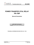
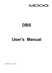
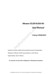
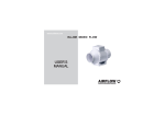
HOW TO USE FIGURE 3.
1.
In the far left vertical column select the appropriate
measured zener voltage at the rated input.
2.
Using a straight edge follow the line across to where
it intersects the 92% diagonal line.
3.
From this point of intersection project down to the
bottom of the graph and read the new zener voltage which
will be arrived at by readjusting the supply voltage.
4.
Repeat Step 1.
5.
Using the straight edge follow the line across to where
it intersects the 88% diagonal line.
6.
From this intersection project down to the bottom and
read the new zener voltage which will be obtained by
once again readjusting the supply voltage (the relay
should NOT pick-up).
8.1
I
?:,~
?:, ~
8.0
QJ
tn
cu
..µ
0
:>
::l
0..
i::
H
/
7.8
..µ
.
:>
7.7
~.,,,,,,,,.
H
rtj
Cl
..µ
:>
QJ ......._
cu
r.:i::
.
..µ
,,::i::o
QJ
tn
7.6
.,,,,..
/
7.5
0
/
7.4
7.3
:>
!-1
QJ
/
7.2
QJ
7.1
.,,,,..
.........
........
.......
/
.,,,,..
-"""'
_,,,. /
.,,,,..
_...
I
7.0
/
6.1
.........
-"""'
.,,,,..
_.,,.
6.2
.,,,,..
,,,,. /
,
./
6.3
6.4
.J"
/
~"""-6.5
-V
.......
/
.,,,,..
6.6
-"""'
.,,,,. ... v
~"""
........
.,,,,.. ........
<:}
'2,~
v....-
~""" ...
/
~v--
........
..., .,,,,..
/
.J"
/
i::
N
/
/
v
~/""
cu
..µ
r-1
.J"
~.,..--
.,,,,..
.J"
/
L{)
0
/
.J"
~~
7.9
r-1
.,.
.,,,,..
v
_..,..
~
.,,,,..
.J"
/
v
........
I./ ~
v
6.7
6.8
6.9
7.0
7.1
7.2
0.02 V/DIV.
Voltage to be used during 88%-92% pick up test.
Figure 3.
PN-150T Calibration Voltage Conversion Table
4587, p. 9/10
UNION SWITCH & SIGNAL
m
that the prod will make contact with the center contact heel
member, which has no terminal finger. To make the test, with
the relay energized and during its pick-up interval, apply the
test prod from the rear of the rack. The voltmeter should read
in a range from 7.0 to 9.0 volts for relays with a suffix number
of -OOX. The voltage should be in the range of 6.8 to 7.8 volts
for relays with -200 and -300 suffix numbers. A higher voltage
would indicate a conditiion that could be hazardous, and the
relay should be removed from service. Once the relay has picked
up, the voltage can be expected to go to a lower value that has
no significance.
IX.
UPDATING THE 001 TO 007 AND 201 TO 208 SUFFIX SERIES
RELAY TO 301 TO 308 SUFFIX SERIES RELAYS
The 001 to 007 and 201 to 208 suffix series relays can be updated to correspond with the 301 to 307 series relays that
have redesigned assemblies to provide a higher overall reliability. The "301 to "307" series are direct replacements
for the former relays of the same basic suffix number; e.g.,
relays with suffix numbers 001 or 201 are replaced with a
suffix number 301 relay.
The delay units for the 301 to 308 series relays are manufactured
for three ranges: 3 to 30 seconds, 1/2 to 5 minutes, and 1
to 10 minutes delay units for the 001-007 series were
manufactured on a basis of time range and voltage. Now, only
the coils determine the voltage rating for the relay.
When ordering replacement delay units for the 001 to 007
series for 12 and 16 volt operation, it is necessary to order
the proper coil so that damage to the delay unit does not
occur. See Table III for information on ordering items to
effect the conversion.
CONVERSION OF 10 VOLT RELAYS (N322523-001, 004, 007, and
N322523-201, 204 and 207
The conversion of all 10 volt relays involves changing only
the delay unit and recalibrating the relay. The following
procedure outlines the necessary steps:
(1)
Remove the old delay unit by removing the two
screws on the contact block of the relay, and
unsoldering the delay unit wires.
NOTE
On some of the suffix 001, 004 and 007 relays,
the wire from the delay unit to the "C" terminal
must be cut. A wire will not be reconnected
to this terminal.
4587, p. 11
UNION SWITCH & SIGNAL
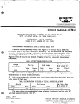
(2)
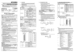
Install the new delay unit and wire it as shown
in Figure 4, being careful to get good solder
joints. Note that there is no new connection
made to the contact finger over which the delay
unit sits.
(3)
Calibrate the relay as detailed in Section VII
of this manual.
(4)
Reseal the screw heads in the contact block
using cement A41225.
(5)
Change first digit of suffix number on nameplate
to 2.
Figure 4.
Wiring for Converted 10 Volt Relays
CONVERSION OF 12 AND 16 VOLT RELAYS 006
(N322523-002, 003, 005,
Conversion of the 12 and 16 volt relays involves replacing
both the coil and the delay unit. The following procedure
outlines the necessary steps:
(1)
Remove the coil from the relay by disconnecting
the plug-jack connectors.
(2)
Remove the red and black coil wires from the
relay by unsoldering them from the contact
block.
·
(3)
Remove the old delay unit by removing the two
screws in the contact block and unsoldering the
delay unit wires.
4587, p. 12
UNION SWITCH & SIGNAL
(4)
Carefully drill a #6 drill size hole in the relay
frame adjacent to the existing hole used for the
red and black coil wires. Deburr the hole and
round the edges, using a slightly larger drill
(1/4" dia.) on both sides.
(5)
Place the new coil on the relay frame, routing
the red and black leads through the original
hole and the two white leads through the new
hole. Lay the excess wire in the open area
under the coil. Pack the area around the
holes with dux seal A41498 to seal the holes.
(6)
Route the wires through the relay as shown in
Figures.
(View A and B).
(7)
Install the new delay unit and wire as shown in
Figure 5.
(Make the splice between the red and
white wire as neatly as possible so that the
insulating tubing will slip easily over :the
joint. Per view A). Check for bad solder joints
and short circuits.
(8)
Adjust and calibrate the relay as detailed in
Section VII of this manual.
(9.)
Seal the delay unit screw leads in the contact
block, using cement A4122:5.
(·10)
Change first digit of suffix number on nameplate
to 2.
NOTE
The indexing pins on the relay do
not change since the 301 to 307
suffix relays are direct replacements of the former design.
Conversion Of 12 and 16 Volt Relays - N322523-202, 203,
204, 206, 208, 803 and 806)
For conversion of 12 and 16 volt
relays with part numbers N322523-202,
203, 205, 206, 208, 803, and 806, the
procedure will be the same as the above,
except the coil will not change.
4587, P· 13
m
f£
.i::,.
u,
00
c
-....]
z
0
z
~
'"d
I-'
-I
0
.i::,.
J:
Ill'
c=::::J
c:::::::J
c::::::J
c=::::J
~
~
~
~
en
c5
z
)>
r
E::3
View A. Wiring for White Wires
Figure 5.
View B. Wiring for Red & Black Wires
Wiring for Converted 12 and 16 Volt Relays
TABLE III
RELAY PART NUMBERS AND CORRESPONDING UP TO DATE COIL AND UP TO DATE DELAY UNIT PART NO. 'S
000 Series
N322523-001
N322523-002
N322523-003
N322523-004
N322523-005
N322523-006
N322523-007
200 Series
300 Series
Volts
N322523-201
N322523-301
10
N322523-202
N322523-302
12
N3 2 2523-20 3
16
N322523-303
N322523-204
N322523-304
10
N3 22523-205
N322523-305
12
N3 22523-20 6
16
N3 22523-30 6
N322523-207
10
N3 22523-30 7
12
N32252 3-30 8
N322523-208
*The existing coil is not changed on 10 volt
unless defective on old relay.
Time Range
UP TO DATE
COIL
l
UP TO DATE
DELAY UNIT
N437608
N399531
3-30 sec.
N437608
N399531-001
3-30 sec.
N437608
N399531-002
3-30 sec.
N437608
1/2-5 min.
N399531
N437608
N399531-001
1/2-5 min.
N437608
N399531-002
1/2-5 min.
N437608
1-10 min.
N399531
N399531-001
N437608
1-10 min.
relays and need not be purchased
-001
-001
-001
-002
-002
-002
-003
-003
UNION SWITCH & SIGNAL
SECTION X
PARTS LIST
STYLE PN-150T TIME ELEMENT RELAY
SUFFIX SERIES 301 to 308
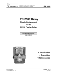
(Reference Figure 7)
ITEI1
1
2
3
4
5
6
7
8
9
10
11
12
13
14
15
16
17
18
19
20
21
22
23
24
25
26
27
28
29
30
31
32
33
34
DESCRIPTION
Frame
Latch Rod
Speed Nut
Latch
Dowel Pin
Spring
Armature Complete(use Figure 6 &
previous parts list for detail
parts).
Washer
Screw, #6-32 x 7/16 Fil. Hd. Sh.
(Tin P:l.)
Contact Block Complete
Tension Washer
Screw, #8-32 x 7/8 Rd. Hd. Stl.
Mach. (Tin Pl.)
Operating Arm
Permanent Magnet Assembly
(Magnetized)
Strap
Screw, #8-32 x 1-1/4 Hed. Hd.
St:l. (Tin Pl.)
Bronze Screw
Handle
Lockwasher, #10 (Int. Tooth) Ph.
Bz. N.P.
Screw, #10-32 x 3/8 Rd. Hd. Brs.
N.P.
Coil (See Table III for part No.)
Screw, 1/4-20 x 3/4 Hex. Cap.
Stl. (Tin P:l.)
Screw, #4-40 x 3/16 Rd. Hd. Stl.
(Tin Pl.)
Name Plate
Indexing Pin
Gasket
LEX.AN
Cover
Screw, #6-32 x 5/1~ Rd. Hd. Stl.
(Tin Pl.)
Washer
Screw
Seal Wire
Seal
Calibration Tag
Screw, #6-32 x 1-1/4 Fil. Hd. Stl
Mach. (Tin Pl.)
WABCO Part #
M399420
M388888
J480176
M321728
J48716
M321861
N399421
M291657
J52243
N399434-0001
J475104
J52603
M399422
M399444
M321853
J463078
M327179
M321821
J47710
J51666
-
J50016
J525024
M433535
J487090
J47081
M437058
J525030
M347631
M321747
J43013
J79351
83665
J52246
4587, p. 15
ffi
~
,I:>,
Ul
~
c
z
5
z
~
'I
I
"------,
---------,-..11
" - - - - - - - - , - - - - - - - - - [ ___ _;
~-·
0
J:
00
--J
•1
8- 7/32 REF.
'U
T0
6
I-'
4
5
C!'I
,7=-=-----= .::r ::tr-~-=-----~....---.-..-. .......
(!
1.
2- 7/16
REF.
3
I
t
I
1:I
If
:o
:I
l:
:
:
:
H--_:
=~--~_-;- ------;_=:.
:j
'\
-_-_J_ _
~\.- - - - - - - - - - - --- --:.....- -- --=--
c.J
~
en
c5
z)>
r
2
-=---~
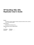
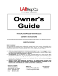
(FOR 12 AND 16 VOLT
UNITS ONLY)
SECTION "H-H"
22
33
21
39
-JF-... 40
23
24
9
ROW A--
8
1
6
5
'I
3
2
IO
oooooooeoo
25
8 ....
co-
7-1/16
REF.
37
18
~
C!!!:I
c:::J
=
=
s
10
11
12
7
8
9
~1111
c;;;;:i
= = =
3 4 ~ 1111
<lJ
0
5
0~
10
FRONT COVER REMOVED
26
Figure 7.
28
29
27
(FOR 10 VOLT UNIT)
Style PN-150T Time Element Relay-, Suffix Series 301 to 308
UNION SWITCH & SIGNAL
ITEH
DESCRIPTION
Screw
Screw Plug
Tubing, #10 Ins. (1-1/8" Long)
Delay Unit (See Table III for
part numbers)
Tag
Screw, #4-40 x 3/16 Rd. Hd. Type
"F'' Self Tapping (Tin Pl.)
35
36
37
38
39
40
NOTE
WABCO Part #
M.399423
M.390716
A774030
J75828
J525024
Parts bag is shipped with each new relay and
is tied to the relay handle. The parts bag
contains:
(1)
(1)
(1)
(2)
(2)
Instruction Tag,
Nomenclature Tag,
Indexing Plate
#4-40 x 3/16" Rd. Hd. Stl. (Tin Plate)
Screws,
#6-32 x 1-1/4" Fil. Hd. screws.
4587, p. 17
ffi
ffi
UNION SWITCH & SIGNAL
PARTS LIST
MOUNTING BASE FOR PN-150T TIME ELEMENT RELAYS
SUFFIX SERIES 301 TO 308
(Reference Figure 9)
ITEB
DESCRIPTION
Mounting Base, Compl. with
Solderless Type Receptacle and
Mounting Hardware
la
lb
le
2
3
4
5
6
7
8
9
10
11
NOTE A:
Receptacles, Contact Solderless
Type for #10 to 112 Wire
Receptacles, Contact Solderless
Type for #14 to #16 Wire
Receptacles, Contact Solderless
Type for #18 to #20 Wire
Mounting Base Only
Screw, #6-32 x 5/8 Fil. St.
Screw, #4-40 x 3/16 (F) Self
Tap. Rd. (Tin Pl.)
Washer (Not Shown) (See Note "B")
Screw, 1/4-20 x 1-1/4 Rd. Stl.
(Tin P:l.) (Not Shown)
Washer, .1/ 4 Stl. Lock (M) (Tin
P:l.) (Not Shown)
Washer, 1/4 Stl. Plate (Tin Pl.)
(Not Shown)
Nut, 1/4 Stl. Hex (Tin Pl.)
(Not Shown)
Meter Test Plug
Insulated Test Plug, used for
opening any coil or contact
circuit and for removing
receptacle Springs
When "Mounting Base Complete"
is ordered a muslin bag of Parts
4-1/8 11 x 5-1/2 11 is included in
the inner carton with mounting
base and instruction Prints.
Bag Contains:
(2)
(4)
(2)
(2)
4587, p. 18
Tags
#4-40 scrs. x 3/16" Rd. Hd.
Stl .. :T.P.
Lockwashers 1/4" Steel
( tin Plated)
Flatwashers 1/4" Hx. Hd.
Stl. (Tin Plated)
WABCO Part#
N399506
(Note A)
J680181
J680165
J680179
N399506-099
M322965
J077931
r
- T O OPl!N CIIICUIT ~
0 _
APPLY A90Y[
R[C[l'TACL[ SPAIN(;
[ _ ___L
I
J
1~:>:'fd~~~:-i~~:: ~
6~
A1dd":-'.,VA9"Jilf -,p,,:,-... -
®
'\ 'I J
D
D
' I
D
~
INDEXING PLATE AND
MOUNTING SCREWS
FURNISHED WITH RELAY
~"
7rg
7~·
0
0
\ll~t.Jll:J
~ [J ~
I\
~~ ~I
~ t_J ~
,Hg~ IQl
\U
K;J [J
~
,~
(J0g0~ ,
''"
~
~
'---
~
l-
'\
~
,g:..
u,
00
-...]
~
t-0
"
= I ~~ f=
= I ~,~~I=
D
0~,
~
~@
-~
-,-
~
®
~
""''\;
CONTACT SPRINGS
ON RELAY
D
"""'
--
(' (' (' ('(' ('
"
('('/:. ('
('('('((('("(:(-[
>('/ ("(' ('
?(' ~
err re rec r
= = =
\I = = =
= =
c::l
=
c::l
c::::J
h
r
= = =
c
I'"~"--~
z
i5
z
I
-.r--i 32
~:::c
7"
(II
, ..
119"
2il
g,
c5
z
l>
I-'
r
\.0
Figure 9. Mounting Base for PN-150T (Time Element Relay, Suffix Series 201 to 207
~
ffi
UNION SWITCH & SIGNAL
ITEI1
DESCRIPTION
(2)
(2)
(2)
Nuts 1/4" Hx. Hd. Stl. T.P.
Washers
Screws 1/4" - 20 x 1-1/4"
Rd. Hd. Stl.
and
(Reg' .:d. Quant.) Contact
Receptacles, Solderless J680165
for #14 to #16 wi~e. If other
wire size is used request the
proper Part Number as shown in
Item 1 when ordering base
complete.
(i.e. N399506 except
using Contact Receptacles,
Solderless J680181)
NOTE B:
4587, p. 20
Items 5 to 9 inclusive are for
attachTng mounting base to rack
and are contained in the muslin
bag shipped with the "Mounting
Base Complete" part number.
WABCO Part#
UNION SWITCH & SIGNAL
PERIODIC MAINTENANCE
All vital relays must be inspected and tested at least every
two (2) years. The tests and inspections are to include:
pick-up current, drop-away current, timing of slow operating
and timing relays, visual inspection of contacts for damage or
misalignment, corrosion, or other contamination of parts, loose
parts inside of cover, broken seal, and cracked or broken cover.
All vital relays installed in locomotive or car-carried
equipment are to be inspected and tested at least every two (2)
years as above.
In addition, every four (4) years the relays
are to be removed from service and adjusted, repaired and
tested.
Relays not passing the above stated tests and inspections must
be replaced and not returned to service until the operating
characteristics and conditions are in accordance with US&S
specifications.
4587, p. 21
m
UNION SWITCH &SIGNAL DIVISION
HEADQUARTERS
American Standard Inc. Swissvale, PA 15218
(412) 273-4000
EASTERN OFFICES
WESTERN OFFICES
PHILADELPHIA
OFFICE
2 Penn Center Plaza
Room 1630
Philadelphia, PA 19102
(215) 568-8032
ST. PAUL
OFFICE
402 McColl Bldg.
5th & Jackson
St. Paul, MN 55101
(612) 222-7562
JACKSONVILLE
OFFICE
P.O. Box 8609
Jacksonville, FL 32211
(904) 724-2607
903 Sneath Lane
Suite 2300
San Bruno, CA 94066
(415) 588-6788
Or 6789
NEW YORK
OFFICE
40 W. 40th. St.
Room 1105
New York, NY 10018
(212) 840-5438
840-5439
SAN
FRANCISCO
OFFICE
ST. LOUIS
OFFICE
500 Northwest Plaza
Suite 820
St. Ann, MO 63074
(314) 291-7400
CANADIAN OFFICE
MONTREAL
OFFICE
1155 Dorchester
Blvd.,W.Suite 1003
Mont.,PQ Can.,H3B 2J2
(514) 866-3677
REGIONAL OFFICES
ATLANTA
(404) 458-5916
ROANOKE OFFICE
(703) 989-8400
HUNTINGTON OFFICE
(304) 736-2629
CHICAGO OFFICE
(312) 759-3577
OMAHA OFFFICE
(402) 334-1516
MAIL ALL ORDERS TO:
ORDER ENTRY DEPARTMENT
UNION SWITCH & SIGNAL DIVISION
AMERICAN ST AND ARD INC.
SWISSVALE PA 15218