1
-49589749 /4964:
.534621 34 0#/#,
-%$&2
-%%#2
+('7$%*$
)7+)
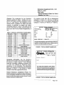
Emissions Supplement: 900-1 021
Date: 07-2000
Insert withManual Number & Date: See Table 1
Models: See Table 1
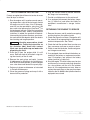
Purpose: This supplement for the Operator's
Manuals specified in Table 1 clarifies how compliance with engine emissions regulations, including U. S. EPA Phase 2 and California Air Resources Board regulations for Model Year 2000
onwards, is presented on genset and engine
nameplates (Figures 1 and 2). This sheet is to be
bound in the genset or engine manual behind the
front cover and in front of earlier Supplements, if
any.
For engines of less than 225 cc displacement,
Category C = 125 hrs, B = 250 hrs, A = 500 hrs.
For engines of 225 cc and greater displacement,
Category C = 250 hrs, B = 500 hrs, A = 1000 hrs.
r
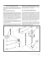
IMPORTANT ENGINE INFORMATION
CURRMlNS POWER GENERATlOM
1400 73rd Avo. NE
Minneapolis, MN 55432
Modd No:
Made in USA
PH
TABLE 1. MANUALS AFFECTED BY SUPPLEMENT
Manual No.
965-0138
I
I
I
965-0175
965-0176
981-0153
981-0158
981-0159
981-0160
983-0101
Manual No.
965-0163
965-0174
965-0178
I
I
965-0179
965-0180
965-0182B
965-0183
I Date 1
I
I
I
I
I
1
I
5/97
7/97
7/97
7/97
6/99
5/00
7/99
5/00
Date
I
1
Genset Models
BGM / NHM
1
I
I
KVC
KY
I
I
I
I
1
I
I
I
7/97
7/97
7/97
1 I -
I
I
I
I
I
Bat:
- NEMA
Qan F
DiagME
Ambiant 40°C
flhe engine family designation, engine displacement, statement of
compliance with the applicable EPA and/or California emissions
regulations, including the complianceperiod or category; appear in
this block on the actual nameplate on the genset.]
FIGURE I.TYPICAL GENSET NAMEPLATE
I 10/95 I Miller P216 / P218 / P220 I P224
I 10/97 I
RPM
wring
InsuIatbn
MKY
HGJAAIHGJABIHGJAC
Engine Models
kW:
pf:
Ha
BGD INHD
BGE / NHE
KV
I
I
kVA:
E124V Floorcare
E125V/ E140V
E125H I E140H
P218V IP220V
P216 / P218 / P220 I P224
I
P248V Floorcare
I
f IMPQRTAMT ENGINE
)
INFORMATION
ONAN C O R P O R A T I O N
1400 7 3 r d A v e .
NE
M i n n e a p o l i s , M N 55432
M a d e in C a n a d a
E n g i n e Model:
Nameplate Information: See the Operator's
Manual for the location of the actual nameplate on
the genset or engine. Figures 1 and 2 illustrate
where the information regarding compliance with
U. S. EPA and California Air Resources Board
regulations on the nameplate. The appropriate
figure in this supplement supercedes the nameplate
illustration in Figure 1 in the genset or engine
manual in which the supplement is bound.
Federal Emissions Compliance Period: The
Federal Emissions Compliance Period referred to
on the nameplate indicatesthe number of operating
hours for which the engine has been shown to meet
Federal emissions requirements.
SIN:
r h e engine family designation, engine displacement, statement of compliance with the applicable
EPA and / or California emissions regulations, including the compliance period or category; appear in
this block on the actual nameplate on the engine.]
FIGURE 2. TYPICAL ENGINE NAMEPLATE
Redistribution or publication of this document,
by any means, is strictly prohibited.
Page 1 of 1
Safety Precautions
Before operating the engine, read this manual and become
familiar with it and the equipment. Safe and efficient
operation can be achieved only if the equipment is
properly operated and maintained.
The following symbols, found throughout this manual, alert you
to potentially dangerous conditions to the operator, service personnel, or the equipment.
This symbol warns of immediate hazards
which will result in severe personal injury or death.
3'.+*+) This symbol refers to a hazard or unsafe
practice which can result in severe personal injury or
death.
('10*,+ This symbol refers to a hazard or unsafe
practice which can result in personal injury or product or
property damage.
Fuels, electrical equipment, batteries, exhaust gases and
moving parts present potential hazards that can result in severe
personal injury. Take care in following these recommended
procedures. All local, state and federal codes should be
consulted and complied with.
3'.+*+) This engine is not designed or intended for
use in any type of aircraft. Use of this engine in aircraft can
result in engine failure and cause severe personal injury or
death.
GENERAL
• Provide appropriate fire extinguishers and install them in
convenient locations. Use an extinguisher rated ABC by
NFPA.
• Make sure that all fasteners on the engine are secure and
accurately torqued. Keep guards in position over fans,
driving belts, etc.
• If it is necessary to make adjustments while the engine is
running, use extreme caution when close to hot exhausts,
moving parts, etc.
• Used engine oils have been identified by some state and
federal agencies as causing cancer or reproductive
toxicity. When checking or changing engine oil, take care
not to ingest, breathe the fumes, or contact used oil.
• Do not work on this equipment when mentally or
physically fatigued, or after consuming any alcohol or
drug that makes the operation of equipment unsafe.
BATTERIES
• Before starting work on the engine, disconnect batteries
to prevent inadvertent starting of the engine. Disconnect
negative (–) cable first.
• DO NOT SMOKE while servicing batteries. Lead acid batteries give off a highly explosive hydrogen gas which can
be ignited by flame, electrical arcing or by smoking.
• Verify battery polarity before connecting battery cables.
Connect negative (–) cable last.
PROTECT AGAINST MOVING PARTS
• Do not wear loose clothing in the vicinity of moving parts,
such as PTO shafts, flywheels, blowers, couplings, fans,
belts, etc.
• Keep your hands away from moving parts.
FUEL SYSTEM
• DO NOT fill fuel tanks while engine is running.
• DO NOT smoke or use an open flame in the vicinity of the
engine or fuel tank. Internal combustion engine fuels are
highly flammable.
• Fuel line must be of steel piping, adequately secured, and
free from leaks. Piping at the engine should be approved
flexible line. Do not use copper piping for flexible lines as
copper will work harden and become brittle enough to
break.
• Be sure all fuel supplies have a positive shutoff valve.
• Benzene and lead, found in some gasoline, have been
identified by some state and federal agencies as causing
cancer or reproductive toxicity. When checking, draining
or adding gasoline, take care not to ingest, breathe the
fumes, or contact gasoline.
EXHAUST SYSTEM
• Exhaust products of any internal combustion engine are
toxic and can cause injury, or death if inhaled. When
operating the engine in a confined area, make sure the
ventilation system is operating properly.
• DO NOT use exhaust gases to heat a compartment.
• Make sure that your exhaust system is free of leaks. Make
sure that exhaust manifolds are secure and are not
warped by bolts unevenly torqued.
EXHAUST GAS IS DEADLY!
Exhaust gases contain carbon monoxide, a poisonous gas that
can cause unconsciousness and death. It is an odorless and
colorless gas formed during combustion of hydrocarbon fuels.
Symptoms of carbon monoxide poisoning are:
• Dizziness
• Vomiting
• Headache
• Muscular Twitching
• Weakness and Sleepiness • Throbbing in Temples
If you experience any of these symptoms, get out into fresh air
immediately, shut down the unit and do not use it until it has
been inspected.
The best protection against carbon monoxide inhalation is
proper installation and regular, frequent inspections of the
complete exhaust system. If you notice a change in the sound
or appearance of exhaust system, shut the unit down immediately and have it inspected and repaired at once by a competent
mechanic.
KEEP THE UNIT AND SURROUNDING AREA CLEAN
• Make sure that oily rags are not left on or near the engine.
• Remove all unnecessary grease and oil from the unit.
Accumulated grease and oil can cause overheating and
subsequent engine damage and present a potential fire
hazard.
Redistribution or publication of this document,
by any means, is strictly prohibited.
Table of Contents
Title
Page
Safety Precautions . . . . . . . . . . . . . . . . . . . . . . . . . . . . . . . . . . . . . . . . . . . . . . . . . . . . . . . . Inside Front Cover
Introduction . . . . . . . . . . . . . . . . . . . . . . . . . . . . . . . . . . . . . . . . . . . . . . . . . . . . . . . . . . . . . . . . . . . . . . . . . . . . . . . 2
Operation . . . . . . . . . . . . . . . . . . . . . . . . . . . . . . . . . . . . . . . . . . . . . . . . . . . . . . . . . . . . . . . . . . . . . . . . . . . . . . . . 5
Periodic Maintenance . . . . . . . . . . . . . . . . . . . . . . . . . . . . . . . . . . . . . . . . . . . . . . . . . . . . . . . . . . . . . . . . . . . . . . 8
Adjustments . . . . . . . . . . . . . . . . . . . . . . . . . . . . . . . . . . . . . . . . . . . . . . . . . . . . . . . . . . . . . . . . . . . . . . . . . . . . 13
Troubleshooting . . . . . . . . . . . . . . . . . . . . . . . . . . . . . . . . . . . . . . . . . . . . . . . . . . . . . . . . . . . . . . . . . . . . . . . . . 15
Specifications . . . . . . . . . . . . . . . . . . . . . . . . . . . . . . . . . . . . . . . . . . . . . . . . . . . . . . . . . . . . . . . . . . . . . . . . . . . 16
Important Information for California Engine Users . . . . . . . . . . . . . . . . . . . . . . . . . . . . . . . . . . . . . . . . . . . 17
WARNING Improper service or replacement of parts
can result in severe personal injury and equipment
damage. service personnel must be qualified to perform
electrical and/or mechanical service.
CALIFORNIA PROPOSITION 65 WARNING
Engine exhaust from this product contains chemicals
known to the State of California to cause cancer, birth
defects, and other reproductive harm.
Redistribution or publication of this document,
by any means, is strictly prohibited.
1
Introduction
ABOUT THIS MANUAL
This manual covers the operation and maintenance
of the vertical-shaft Performer Series of engines.
Each operator of the power equipment should study
this engine manual carefully and observe all of its
instructions and precautions. Proper use and periodic maintenance are responsibilities of the operator(s) and are essential for top performance.
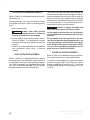
P220V–I/11264F
L951234567
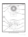
MODEL IDENTIFICATION
Whenever contacting an Onan dealer or distributor
for information, parts or service, always provide the
model number and the serial number marked on the
nameplate of the engine. Figure 1 illustrates a typical engine nameplate and Figure 2 the location of
the nameplate on the engine.
Genuine Onan replacement parts obtained from an
Onan dealer or distributor are recommended.
2
THIS ENGINE MEETS U.S. EPA PH1 AND 1995-1998
CALIFORNIA EMISSIONS REGULATIONS FOR
ULGE ENGINES.
SN5782U1G2RA
782
FIGURE 1. TYPICAL ENGINE NAMEPLATE
Redistribution or publication of this document,
by any means, is strictly prohibited.
FUEL PUMP
ELECTRIC
STARTER
OIL FILL CAP
FLYWHEEL AIR
INLET SCREEN
OIL FILTER
THROTTLE
CABLE CLAMP
BATTERY
CHARGING
VOLTAGE
REGULATOR
AIR FILTER
HOUSING
NAMEPLATE
LOCATION
SPARK PLUG
SPARK PLUG
OIL DRAIN
FUEL FILTER
CRANKSHAFT
FIGURE 2. TYPICAL ENGINE CONFIGURATION
Redistribution or publication of this document,
by any means, is strictly prohibited.
3
FUEL RECOMMENDATIONS
Use clean, fresh unleaded gasoline having a minimum octane rating (Anti-Knock Index) of 87.
During some times of the year only mandated “oxygenated” gasolines may be available. These are
acceptable for use, but not preferable. Leaded gasoline may be used but will result in the extra maintenance required for removing combustion chamber
and spark plug deposits. Do not use gasoline or
gasoline additives (de-icers) containing methanol
because methanol can be corrosive to fuel system
components.
('10*,+
Do not use gasoline or gasoline additives containing methanol because methanol
can be corrosive to fuel system components.
Avoid using highly leaded gasolines and lead
additives because of the extra engine maintenance that will be required.
3'.+*+)
Gasoline is highly flammable and
can cause severe personal injury or death. Do
not smoke if you smell gasoline or are near fuel
tanks or gasoline-burning equipment or are in
an area sharing ventilation with such equipment. Keep flames, sparks, pilot lights, electrical arcs and arc-producing equipment and all
other sources of ignition well away.
ENGINE OIL RECOMMENDATIONS
Use premium quality motor oil. Look for the API
(American Petroleum Institute) classification and
use Class SG or SH oil (also SG/CD, SG/CE, SH/
CD or SH/CE). Also look for the SAE (Society of Automotive Engineers) viscosity grade. Referring to
Table 1, choose the viscosity grade appropriate for
the ambient temperatures expected during the period of time until the next scheduled oil change.
Single-grade SAE 30 oil is preferable when temperatures are consistently above freezing. Multigrade
oils are better when wide temperature variations
are expected.
4
TABLE 1. OIL VISCOSITY VS. TEMPERATURE
EXPECTED AMBIENT
TEMPERATURES
SAE
VISCOSITY
GRADE
32° F (0° C) and higher
30
10° F to 100° F (–12° C to 38° C)
15W-40
(OnaMax)
0° F to 80° F (–18° C to 27° C)
10W-30
10W-40
–20° F to 50° F (–28° C to 10° C)
5W-30
STARTING BATTERIES
The engine is equipped with a 12 volt electric starter. Prompt starting requires sufficient battery capacity and battery cable size. Neither cranking performance nor starter service life will be satisfactory
with an undersized battery.
Regular, monthly maintenance of batteries may be
required. See Periodic Maintenance and any
instructions available from the equipment or battery
manufacturer. It should be noted that as long as the
equipment is operated regularly, the automatic battery recharging system on the engine should be
able to maintain battery charge. See OUT-OFSERVICE PROTECTION under Operation regarding battery care during storage for prolonged periods.
EXHAUST SYSTEM
EXHAUST GAS IS DEADLY! Mobile engine-powered equipment must never be operated inside
buildings or other enclosed spaces without ample
fresh air ventilation.
Stationary engine-powered equipment installed inside buildings or other enclosed spaces must be
equipped with a leak-free exhaust system that carries all exhaust gases to the outside, well away from
all windows, doors, vents and other openings into
the building or enclosure.
It is the responsibility of the equipment operator(s)
to check for exhaust leaks on a daily basis and to
have all leaks repaired before continuing to operate
the equipment.
Redistribution or publication of this document,
by any means, is strictly prohibited.
Operation
EXHAUST GAS IS DEADLY!
Exhaust gases contain carbon monoxide, an odorless and colorless gas. Carbon monoxide is poisonous and can cause unconsciousness and death. Symptoms of carbon monoxide poisoning include:
•
•
•
•
Dizziness
Nausea
Headache
Weakness and Sleepiness
•
•
•
•
Throbbing in Temples
Muscular Twitching
Vomiting
Inability to Think Coherently
IF YOU OR ANYONE ELSE EXPERIENCE ANY OF THESE SYMPTOMS, GET OUT INTO THE FRESH
AIR IMMEDIATELY. If symptoms persist, seek medical attention. Shut down the engine and do not
operate it until it has been inspected and repaired.
Make certain the exhaust system is properly installed. Inspect it every time the engine is started
and after every eight hours of continuous operation.
PRE-START CHECKS
Before the first start of the day and after every eight
hours of operation perform the maintenance
instructed in DAILY (8 HOUR) MAINTENANCE under Periodic Maintenance. Keep a log of maintenance and the hours run and perform any maintenance that may be due. Also, if the equipment has
been in storage, return the engine to service as
instructed under RETURNING THE ENGINE TO
SERVICE in this section.
Always follow the equipment manufacturer’s operating instructions and observe all precautions when
operating power equipment.
3'.+*+)
Moving parts can cause severe
personal injury or death. Hot exhaust parts can
cause severe burns. Stay clear of hot or moving
parts. Make sure all protective shields and
guards are secure in place before starting up
the equipment.
STARTING
1. Check the oil level if this is the first start of the
day and add oil as necessary.
('10*,+ Starting the engine without oil
will cause severe engine damage. Always
keep the engine oil level between the Full
and Add marks on the dipstick.
2. Fill the fuel tank, if necessary, and open any fuel
line shutoff valve.
3. Release the clutch if the engine is so equipped.
4. Unless the engine is equipped with an automatic choke, pull the choke knob out to its full-choke
position. On equipment with a solenoid operated choke, push the switch to its choke position.
Note: Try starting without the choke in warm
weather or when the engine is warm.
5. Push the throttle knob or lever to the middle of
its speed range.
6. Turn the ignition-start switch to its start position
and hold it there until the engine starts. Do not
crank for more than 30 seconds at a time and
wait at least one minute between tries when
cranking. See Troubleshooting if the engine
does not start after several tries.
7. After the engine starts, unless it is equipped
with an automatic choke, keep your hand on the
choke knob and slowly push it in to the full-open
choke position, pulling back if necessary to
keep the engine running smoothly. The colder
the weather the longer it will take the engine to
start running smoothly with the choke fully
open. Do not operate the equipment until the
engine has warmed up sufficiently to run
smoothly with the choke fully open.
Redistribution or publication of this document,
by any means, is strictly prohibited.
5
ENGINE BREAK-IN
Engine break-in as a result of proper care during the
first hours of operation of a new or rebuilt engine results in the ideal fitting of all internal moving metal
parts, which is essential for top engine performance. For controlled engine break-in:
1. Operate the equipment as it is intended to be
operated. However, for the first 3 hours, if possible, operate the equipment at about half the
available engine power, occasionally operating
at full engine power for brief periods. Also, if
possible, avoid prolonged low-speed, lowpower operation during engine break-in.
2. Proper engine oil is especially critical during
break-in because of the higher engine temperatures that can be expected. See RECOMMENDED ENGINE OIL in Introduction.
Change the oil if it is not appropriate for the ambient temperatures during the break-in period.
See Table 1.
3. Check the oil level twice a day or after every 4
hours of operation during the first 24 hours of
operation.
4. Change the oil and oil filter after the first 24
hours of operation.
OPERATION IN DUSTY CONDITIONS
1. Keep the engine cooling fins and flywheel air
inlet screen clean.
2. Perform air cleaner maintenance more often
than normal—as required. See Table 2.
3. Change the engine oil and oil filter more often
than normal. See Table 2.
6
OPERATION IN HOT WEATHER
Pay particular attention to the following items when
operating the engine in temperatures above 100° F
(38° C):
1. Keep the flywheel air inlet screen and cylinder
cooling fins clean. See to it that nothing obstructs air flow to and from the engine.
2. Check the oil level more frequently.
3. Change the oil and oil filter more often than normal. See Table 2.
4. Make sure the engine oil viscosity is appropriate for the ambient temperatures and change
the oil if necessary. See Table 1.
OPERATION IN COLD WEATHER
Pay particular attention to the following items when
operating the engine in temperatures below freezing:
1. Make sure the engine oil viscosity is appropriate for the ambient temperatures and change
the oil if necessary. See Table 1. If the temperature drops before you have the chance to
change the oil, warm up the engine by moving
the equipment into a heated space before attempting to start the engine or change oil.
3'.+*+) EXHAUST GAS IS DEADLY!
Never operate mobile engine-powered
equipment indoors without ample fresh air
ventilation.
2. Use fresh fuel and fill the fuel tank after each
day’s use to reduce problems with moisture
condensation.
3. Keep the battery in a well-charged condition.
4. After each use push the equipment throttle
knob or lever to the middle of its speed range so
that if ice forms on the linkage during storage it
will be easier to start the engine.
Redistribution or publication of this document,
by any means, is strictly prohibited.
OUT-OF-SERVICE PROTECTION
Protect an engine that will be out of service for more
than 30 days as follows:
1. Run the engine until it reaches normal operating temperature, shut off the fuel supply and let
the engine run until it stops. Also, if the equipment will not be operated for more than 120
days, add a fuel preservative (OnaFreshTM) to
the equipment fuel tank. Follow the instructions
on the container label. Unless a preservative
(stabilizer) is added, the gasoline will deteriorate causing fuel system corrosion, gum formation and varnish-like deposits which can lead to
hard starting and rough operation.
3'.+*+) Gasoline preservatives (stabilizers) are toxic. Follow the instructions on
the container label. Avoid skin contact.
Wash your hands with soap and water after
dispensing the fluid.
2. Drain the oil from the engine while it is still
warm. Refill with fresh oil and attach a tag stating the viscosity of the oil used.
3. Remove the spark plugs and squirt 1 ounce
(2 tablespoons or 28 grams) of rust inhibitor or
SAE 30 oil into each cylinder. Crank the engine
over a few times and reinstall the spark plugs.
4. Perform air cleaner maintenance as instructed
in Periodic Maintenance.
5. Clean the governor linkage and wrap it with a
clean cloth for protection.
6. Plug the exhaust outlet to prevent moisture,
dirt, bugs, etc. from entering.
7. Provide a suitable cover for the entire unit.
8. If so equipped, disconnect the battery (negative [–] cable first) and follow the battery or
equipment manufacturer’s storage instructions.
RETURNING THE ENGINE TO SERVICE
1. Remove the cover and all protective wrapping
and the plug from the exhaust outlet.
2. Check the tag on the oil base. Change the oil if
the viscosity is not appropriate for the expected
ambient temperatures. See Table 1.
3. Check the fuel filter and fuel lines to make sure
they are secure and have no cracks or leaks.
4. Check to see that the choke, throttle and governor linkages move freely.
5. If so equipped, clean and check the battery according to the battery or equipment manufacturer’s instructions and connect the battery
cables (positive [+] cable first).
6. Start the engine. The initial startup may be slow
and there may be smoke and rough operation
for a few minutes until the oil in the cylinder
burns off. If the engine does not start, clean or
replace the spark plugs as they may have been
fouled by the oil added to the cylinder when the
equipment was stored.
OnaFresh is a trademark of the Onan Corporation.
Redistribution or publication of this document,
by any means, is strictly prohibited.
7
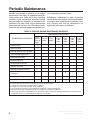
Periodic Maintenance
Periodic maintenance is essential for top engine
performance. Use Table 2 as a guide for normal periodic maintenance. Under hot or dusty operating
conditions some maintenance operations should
be performed more frequently, as indicated by the
footnotes in the table. Keep a log of maintenance
performed and the hours run. Recording maintenance will help you keep it regular and provide a ba-
sis for supporting warranty claims.
Maintenance, replacement or repair of emission
control devices and systems may be performed by
any engine repair establishment or individual. However, warranty work must be completed by an
authorized Onan dealer or distributor.
TABLE 2. PERIODIC ENGINE MAINTENANCE SCHEDULE
MAINTENANCE FREQUENCY
MAINTENANCE OPERATION
Every
Day or
Every 8
Hours
Inspect Engine
•1
Check Oil Level
•
Every 50
Hours
Clean Air Cleaner Foam Wrapper
•3
Clean Cylinder Cooling Fins
•3
Change Engine Oil Filter
Every
500
Hours
Every
1,000
Hours
•2, 3, 4
•2, 3, 4
•
Replace Air Cleaner Element
•3
Adjust Engine Valve
Clearance
•6
Clean Cylinder Heads of Deposits
8
Every
200
Hours
Replace Fuel Filter
Replace Spark Plugs
1
2
3
4
5
6
7
Every
100
Hours
•5
Check Starting Battery
Change Engine Oil
Every
Month
•
•6,7
Check for oil, fuel and exhaust leaks, loose parts and unusual noises and vibrations.
Perform after the first 24 hours of operation as a part of engine break-in.
Perform more often when operating in dusty conditions.
Perform more often when operating in hot conditions.
See instructions for battery care provided by the equipment or battery manufacturer.
Must be performed by a qualified mechanic according to the engine Service Manual.
Clean more often when using leaded fuel or running the engine continuously under light load. Onan 4C carburetor and
combustion cleaner is recommended every 200 hours of operation.
Redistribution or publication of this document,
by any means, is strictly prohibited.
DAILY (8 HOUR) MAINTENANCE
The operator should check the following before the
first start of the day and after every eight hours of
operation:
1. Inspect fuel lines and fittings for leaks. Repair
leaks immediately.
ing an SAE viscosity grade appropriate for the
expected temperatures, as indicated by
Table 1.
DO NOT FILL TO A LEVEL ABOVE THE FULL
MARK ON THE DIPSTICK. Drain the excess
oil if too much has been added.
2. Look and listen for exhaust system leaks while
the engine is running. Look for cracks and severe rusting in the muffler and tailpipe. Have all
leaks repaired before continuing to operate the
equipment.
('10*,+ Too much oil can cause high oil
consumption, high operating temperatures
and oil foaming. Too little oil can cause severe engine damage. Keep the oil level between the Full and Add marks on the dipstick.
3'.+*+) Hot exhaust parts can cause
severe burns. Allow the engine time to cool
before servicing the exhaust system.
Reinstall the dipstick and cap after checking or
adding oil, turning it clockwise until it is secure.
3. Check the engine for dirt and debris and clean
the flywheel air inlet screen and cylinder cooling fins as necessary.
-/7%%+&
('10*,+ A clogged flywheel air inlet
screen or dirty cooling fins can cause overheating and engine damage. Keep the cooling fins and air inlet screen clean.
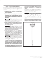
4. Check the engine oil level. The equipment
must be parked on a level surface and the engine stopped. To get an accurate reading, wait
a minute or so to allow the oil to settle in the
crankcase if the engine has been running.
3'.+*+) Crankcase pressure can blow
hot engine oil out the fill tube causing severe burns. Always stop the engine before
removing the oil fill cap.
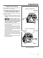
Turn the oil fill cap (Figure 3) counterclockwise
and then lift it from the fill tube. Wipe the dip
stick clean and push it back into the oil fill tube
until the cap seats and then withdraw it to check
the oil level.
If the oil level is low, add API Class SG or SH oil
(also SG/CD, SG/CE, SH/CD or SH/CE) hav-
FIGURE 3. OIL FILL CAP AND DIPSTICK
Redistribution or publication of this document,
by any means, is strictly prohibited.
9
ENGINE OIL AND FILTER CHANGE
5. Thoroughly wipe off the filter mounting surface.
State and federal agencies have determined that contact with used engine oil can
cause cancer or reproductive toxicity. Take
care to limit skin contact and breathing of vapors as much as possible. Use rubber gloves
and wash exposed skin.
6. Make sure the gasket is in place on the filter
canister and apply a thin film of oil to the gasket.
Refer to Table 2 for scheduled oil change and filter
replacement. See Figure 2 on page 3 for oil filter
and oil drain locations.
8. Refill with API Class SG or SH oil (also SG/CD,
SG/CE, SH/CD or SH/CE) having an SAE viscosity grade appropriate for the expected temperatures, as indicated by Table 1. See Specifications for the oil capacity.
3'.+*+)
1. Run the engine until it is warm. Stop the engine
and disconnect the spark plug and, if so
equipped, the battery (negative [–] cable).
3'.+*+) Accidental starting of the engine can result in severe personal injury or
death. Always disconnect the spark plug
and the battery (negative [–] cable) before
changing oil.
2. Remove the oil fill cap.
3'.+*+) Crankcase pressure can blow
hot engine oil out the fill opening causing
severe burns. Always stop the genset before removing the oil fill cap.
3. Place a pan under the oil drain opening and remove the oil drain plug. Reinstall the plug securely after the oil has drained completely.
4. Spin off the oil filter canister, drain the oil and
discard the filter according to local regulations.
10
7. Spin on the new filter canister by hand until the
gasket just touches the mounting pad and then
turn it an additional 1/2 to 3/4 turn. Do not overtighten.
DO NOT FILL TO A LEVEL ABOVE THE FULL
MARK ON THE DIPSTICK. Drain the excess
oil if too much has been added.
('10*,+ Too much oil can cause high oil
consumption, high operating temperatures
and oil foaming. Too little oil can cause severe engine damage. Keep the oil level between the Full and Add marks on the dipstick.
9. Reconnect the spark plug and battery.
10. Start the engine and run it for a short time while
checking for oil leaks around the drain plug and
oil filter. Do not overtighten: tighten only as necessary to eliminate leaks.
11. Used oil is harmful to the environment. Pour
the used oil into a sealed container and deliver
it to the nearest recycling center.
Redistribution or publication of this document,
by any means, is strictly prohibited.
AIR CLEANER MAINTENANCE
Refer to Table 2 for scheduled foam wrapper maintenance and air cleaner element replacement. See
Figure 4.
pletely cover all exposed paper pleats on the air
cleaner paper element. Replace the foam wrapper
when it becomes torn or stretched.
Air Cleaner Element Replacement
Foam Wrapper Maintenance
When performing maintenance on the foam wrapper only, do not remove the inner air cleaner cover.
Remove and wash the foam wrapper in water and
detergent. Squeeze the foam wrapper dry like a
sponge. Rinse with clean water and allow it to dry.
Coat the wrapper evenly with one tablespoon
(14 grams) of SAE 30 engine oil. Knead the oil into
the wrapper and wring out the excess oil.
Failure to adequately wring out excess oil from the
wrapper may cause a drop in engine power due to a
restriction of inlet air.
Install the foam wrapper over the paper air cleaner
element by stretching it over the inner cover. Com-
To keep anything from entering the carburetor and
engine while the air cleaner element is off, pull the
choke knob to the full-choke position to close the
choke plate in the carburetor. Remove the outer
cover and wipe away loose dust and debris from the
air cleaner assembly. Remove the inner air cleaner
mounting nut and cover. Remove the air filter paper
element and foam wrapper from the engine. Wipe
off dust and debris from the air cleaner base.
Install the new paper element and secure it with the
inner cover and mounting nut. Reinstall the foam
wrapper and outer cover. Make sure to reconnect
the the crankcase breather tube.
OUTER
NUT
OUTER
COVER
AIR
CLEANER
ELEMENT
PULL CRANKCASE
BREATHER TUBE
OUT WHEN
REMOVING INNER
COVER
AIR
CLEANER
ASSEMBLY
BASE
INNER
NUT
INNER
COVER
FOAM
WRAPPER
FIGURE 4. AIR CLEANER ASSEMBLY
Redistribution or publication of this document,
by any means, is strictly prohibited.
11
COOLING SYSTEM MAINTENANCE
Refer to Table 2 for scheduled cleaning of the cylinder cooling fins.
Use compressed air or a pressure washer to clean
the cylinder cooling fins. Take the following precautions.
1. Wear safety glasses.
3'.+*+)
Take care not to spill fuel when disconnecting the
fuel line from the filter. Allow the engine to cool before disconnecting the fuel line so that it cannot ignite any fuel that may be spilled. Close any shutoff
valve that may be provided in the fuel line. If the filter
is of the in-line type, it is usually removable by loosening the inlet and outlet hose clamps.
3'.+*+) Gasoline is highly flammable and
can cause severe personal injury or death.
Always wear safety glasses
when using compressed air or a pressure
washer to avoid severe eye damage.
Let the engine cool and close any fuel line shutoff valve before disconnecting the fuel line from
the filter.
2. Let the engine cool, especially when using a
pressure washer. The temperature stresses
caused by cleaning a hot engine can crack the
cylinder.
Do not smoke if you smell gasoline or are near
fuel tanks or gasoline-burning equipment or are
in an area sharing ventilation with such equipment. Keep flames, sparks, pilot lights, electrical arcs and arc-producing equipment and all
other sources of ignition well away.
3. Observe all of the manufacturer’s instructions
and precautions when using a pressure
washer.
FUEL FILTER REPLACEMENT
Refer to Table 2 for scheduled fuel filter replacement and Figure 2 for the location of the fuel filter (if
so equipped). Also refer to the equipment Operator’s Manual regarding any supplemental fuel filters
that may have been provided and the recommended frequency for their replacement.
12
SPARK PLUG REPLACEMENT
Refer to Table 2 for scheduled spark plug replacement and Specifications for gap specifications.
To prevent crossthreading the spark plug always
thread it in by hand until it seats. Then turn it with a
wrench an additional 1/16 turn (22-1/2°). If you have
a torque wrench, tighten the spark plugs to 11 lbs-ft
(14 N-m).
Redistribution or publication of this document,
by any means, is strictly prohibited.
Adjustments
CARBURETOR ADJUSTMENTS
These engines have precision-manufactured carburetors which are not adjustable.
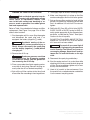
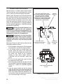
REAR-PULL CHOKE CABLE
CHOKE LEVER
(open position)
RECONNECTING AND RECLAMPING THE
CHOKE CABLE (MANUAL CHOKE)
Referring to Figure 5, reconnect and reclamp the
choke cable as follows:
1. Stop the engine and disconnect the spark
plugs and, if so equipped, the battery (negative
[–] cable).
3'.+*+) Accidental starting of the engine can result in severe personal injury or
death. Always disconnect the spark plug
and battery (negative [–] cable) before resetting the engine control cables.
2. Push the equipment choke knob to the fullopen choke position.
3. Connect the choke cable to the choke lever.
(The cable will either hook into the choke lever
or be clamped by a screw in a swivel on the
choke lever. See Figure 5.) Pull the slack out of
the cable and clamp it.
4. Check for smooth movement and full travel of
the equipment choke knob. Remove the air
cleaner element as explained under Periodic
Maintenance to see that the choke plate opens
and closes fully.
6. Reassemble the air cleaner and reconnect the
spark plug and battery.
CLOSE
CHOKE
CABLE
CLAMP
FRONT-PULL CHOKE CABLE
INTERMEDIATE
LINK AND LEVER
CHOKE LEVER
(open position)
CLOSE
CHOKE
SWIVEL
CLAMP
CABLE
CLAMP
FIGURE 5. FRONT-PULL AND REAR-PULL CHOKE
CABLE ARRANGEMENTS
Redistribution or publication of this document,
by any means, is strictly prohibited.
13
ENGINE SPEED ADJUSTMENT
Normally there is no need to adjust engine speed.
These instructions are for the equipment manufacturer in setting up and adjusting the equipment.
Engine speed adjustment must be attempted only
by a qualified mechanic and the adjustments must
be made using an accurate tachometer. Set the
low-idle and high-idle speeds to the values specified in the equipment Operator’s Manual. In the absence of such specifications it is recommended that
low-idle speed be adjusted to 1,100 RPM and highidle speed to 3,400 RPM.
HIGH-IDLE SPEED STOP TANG
Do not bend the high-idle speed stop
tang unless you are a qualified
mechanic and have an accurate
tachometer to set the high-idle speed
in accordance with the equipment
manufacturer’s specifications
ENGINE
THROTTLE
LINK
3'.+*+) Adjusting the engine speed to a value above that specified by the equipment
manufacture could cause the equipment to operate at speeds in violation of Federal and State
Standards for Safety for the equipment.
3'.+*+) Moving parts can cause severe personal injury or death. Take care when measuring engine speed with a tachometer and follow
the meter instructions. You must be a qualified
mechanic.
Referring to Figure 6, adjust the low-idle and highidle engine speeds as follows:
1. Start the engine, observing all of the equipment
manufacturer’s instructions and precautions.
2. If the throttle cable has already been connected, loosen the clamp at the engine and
back out the low-idle speed stop screw so that
the speed stop screw on the carburetor
touches its stop. Adjust engine speed to
1,000 RPM with the carburetor speed stop
screw.
3. Turn the low-idle speed stop screw to obtain
the specified low-idle speed.
4. Move the engine throttle link up against its stop
tang and hold it there while bending the tang as
necessary to obtain the specified high-idle
speed.
5. Hook the engine throttle link with the throttle
cable, pull the slack out of the throttle cable and
tighten the clamp. Check for full, smooth movement of the engine throttle link between its two
stop positions when the equipment throttle lever is moved through its full range.
14
THROTTLE CABLE
(Pull cable sheath to remove
slack before clamping)
CABLE
CLAMP
LOW-IDLE
SPEED STOP
SCREW
CARBURETOR SPEED STOP
SCREW
FIGURE 6. SPEED ADJUSTMENTS
Redistribution or publication of this document,
by any means, is strictly prohibited.
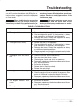
Troubleshooting
Table 3 provides basic troubleshooting guidance. If
you fail to resolve the problem after taking the corrective actions suggested, contact the equipment
or Onan dealer.
sonnel with knowledge of fuels, electricity, and
machinery hazards should perform service procedures. Review the safety precautions on the
inside cover page.
3'.+*+) Many troubleshooting procedures
present hazards that can result in severe personal injury or death. Only qualified service per-
3'.+*+) Hot engine parts can cause severe
burns. Always allow the engine time to cool
before performing any maintenance or service.
TABLE 3. TROUBLESHOOTING
Problem
Corrective Action
1. The engine fails to crank.
a. Release the clutch (if so equipped).
b. Clean and tighten the positive (+) and negative (–) battery
cable connections at the battery and the engine.
c. Recharge the battery. Refer to the equipment or battery
manufacturer’s recommendations.
2. The engine cranks slowly.
a. Release the clutch (if so equipped).
b. Clean and tighten the positive (+) and negative (–) battery
cable connections at the battery and the engine.
c. Recharge the battery. Refer to the equipment or battery
manufacturer’s recommendations.
d. Change engine oil to oil having the proper viscosity for the
ambient temperature. See Table 1.
3. The engine cranks but fails to
start.
a.
b.
c.
d.
4. The engine runs and then stops.
a. Check the fuel tank and fill if necessary.
b. Check the engine oil level and add oil as necessary. Drain
excess oil if the level is above the dipstick Full mark.
c. Reconnect and reclamp the choke cable (manual chokes
only). See Adjustments.
5. The engine exhausts black
smoke.
a. Service the air cleaner.
b. Reconnect and reclamp the choke cable (manual chokes
only). See Adjustments.
6. The engine misfires.
a. Replace the spark plugs.
Check the fuel tank and fill if necessary.
Open any closed fuel shut off valve.
Check engine oil level and add oil as necessary.
Reconnect and reclamp the choke cable (manual chokes
only). See Adjustments.
e. Service the air cleaner.
f. Replace the fuel filter(if provided).
g. Replace the spark plugs.
Redistribution or publication of this document,
by any means, is strictly prohibited.
15
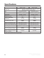
Specifications
MODEL P218V
Engine Type
MODEL P220V
Horizontally Opposed 2-Cylinder, 4-Stroke Cycle, Spark-Ignited,
Side-Valve, Air-Cooled, Vertical-Shaft
Bore
3.250 inches (83 mm)
3.250 inches (83 mm)
Stroke
2.875 inches (73 mm)
2.875 inches (73 mm)
48 inches3 (782 cc)
48 inches3 (782 cc)
7.0 : 1
7.0 : 1
18 HP
(13.4 kW)
20 HP
(14.9 kW)
2 quarts
(1.9 l)
2 quarts
(1.9 l)
Intake Valve Clearance (Cold)
0.005 inches (0.13 mm)
0.005 inches (0.13 mm)
Exhaust Valve Clearance (Cold)
0.013 inches (0.33 mm)
0.013 inches (0.33 mm)
Spark Plug Gap
0.025 inches (0.64 mm)
0.025 inches (0.64 mm)
Spark Plug Tightening Torque
11 lbs-ft
(14 N-m)
11 lbs-ft
(14 N-m)
Ignition Timing (Non-adjustable
electronic ignition)
20° BTDC
20° BTDC
Displacement
Compression Ratio
Power at Rated Speed
(3600 RPM)
Oil Capacity (with Filter)*
* –See Periodic Maintenance for oil filling instructions.
16
Redistribution or publication of this document,
by any means, is strictly prohibited.
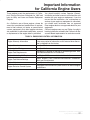
Important Information
for California Engine Users
These engines meet the requirements of California’s Exhaust Emissions Standards for 1995 and
later for Utility and Lawn and Garden Equipment
Engines.
As a California user of these engines, please be
aware that unauthorized modifications or replacement of fuel, exhaust, air intake, or speed control
system components that affect engine emissions
are prohibited. Unauthorized modification, removal
or replacement of the engine label is prohibited.
You should carefully review Operator (Owner),
Installation and other manuals and information you
receive with your engine or equipment. If you are
unsure that the installation, use, maintenance or
service of your engine or equipment is authorized,
you should seek assistance from an approved
Onan engine dealer or an approved dealer for your
equipment.
California engine users may use Tables 4 as aids in
locating information related to the California Air Resources Board requirements for emissions control.
TABLE 4. EMISSIONS CONTROL INFORMATION
Engine Warranty Information
The California emissions control warranty statement is located
in the same packet of information as this manual when the engine is shipped from the factory.
Engine Valve Lash
See Specifications.
Engine Ignition Timing
See Specifications.
Engine Fuel Requirements
The engine is certified to operate on unleaded gasoline. See
Fuel Recommendations in Introduction.
Engine Lubricating Oil Requirements
See Engine Oil Recommendations in Introduction.
Engine Fuel Mixture Settings
These engines have precision-manufactured carburetors
which are not adjustable.
Engine Adjustments
See Adjustments.
Engine Emission Control System
The engine emission control system consists of internal engine
modifications.
Redistribution or publication of this document,
by any means, is strictly prohibited.
17
Cummins Power Generation
1400 73rd Avenue N.E.
Minneapolis, MN 55432
763-574-5000
Fax: 763-528–7229
Cummins and Onan are registered trademarks of Cummins Inc.
Redistribution or publication of this document,
by any means, is strictly prohibited.