1
CHAPTER 8
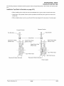
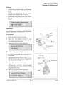
BRAKES I FINAL DRIVE
Jackshaft Speed vs. MPH Chart ...................................... 8.1-8.2
HYVO"' Chains & Sprockets ......................................... 8.3
Sprocket I Chain Combinations 6 5/8" Chaincase ....................... 8.4
Sprocket I Chain Combinations 7.05" Chaincase ........................ 8.5
1999 Track Drive Data .............................................. 8.6
Driveshaft Sprocket Installation Tips ................................... 8.7
Track Specifications ................................................ 8.8
Hydraulic Brake System Operation .................................... 8.9
Type 3 Master Cylinder .............................................. 8.10
Type 3 Master Cylinder Inspection and Assembly ....................... 8.11-8.13
Brake Bleeding - Fluid Change ....................................... 8.14-8.15
Hayes"' Master Cylinder ............................................ 8.16
Hayes"'
Inspection and Replacing Cartridge Subassembly ............. 8.16-8.20
Hayes"'
Master Cylinder Lever and/or Pin Replacement ................ 8.21-8.22
Hayes"' Park Brake Lever and/or Spring Replacement .................. 8.23-8.24
Type H4 Friction Pad Replacement ................................... 8.25-8.26
Type H4 Caliper Disassembly ........................................ 8.27
Type H4 Cleaning and Inspection ..................................... 8.28
Type H4 Assembly .................................................. 8.28-8.29
Type H5LC Friction Pad Replacement ................................. 8.30-8.31
Type H5LC Caliper Disassembly ...................................... 8.32
Type H5LC Cleaning and Inspection .................................. 8.33
Type H5LC Assembly ............................................... 8.33-8.34
Type M3 Disassembly ............................................... 8.35
Type M3 Assembly to Chaincase ..................................... 8.36
Type M3 Adjustment ................................................ 8.37
Type WT Disassembly .............................................. 8.38
Type WT Assembly to Transmission ................................... 8.39
Type WT Adjustment ................................................ 8.39
Type 3 Drive System Disassembly .................................... 8.40-8.43
Type 3 Drive System Assembly ....................................... 8.44-8.51
Transmission, Suspension and Track Removal- WideTrak ............... 8.52-8.54
Transmission, Suspension and Track Assembly- WideTrak .............. 8.55-8.59
Transmission Disassembly, Wide Trak LX .............................. 8.60-8.66
Transmission Assembly, Wide Trak LX ................................ 8.66-8.67
Brake Caliper Removal- Type WT2 ................................... 8.67
Brake Caliper Assembly/Installation - Wide Trak LX ..................... 8.68
Reverse Kit Service Tips ............................................. 8.69
Reverse Kit Maintenance ............................................ 8.70-8.72
Traction ........................................................... 8.73
Stud Recommendations ............................................. 8.74-8.76
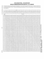
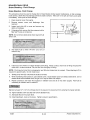
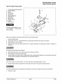
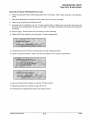
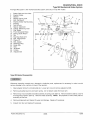
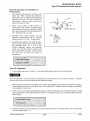
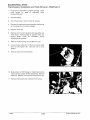
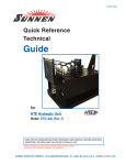
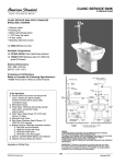
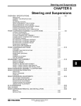
INDY JACKSHAFT SPEI:...., VS. MILES PER HOUR
SPROCKET COMBINATION/GEAR RATIO/CHAIN PITCH- STD. CHAINCASE
~
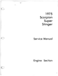
The following chart should be used to select optimum gearing for special applications. The chart is calculated for models with the P85 drive clutch at a 1 to 1 ratio between drive clutch and driven
CiJ·
clutch front drive sprocket diameter is 7.06 inches. To use the chart, select the jackshaft rpms (equal to engine rpm). MPH is shown to the right of jackshaft rpm. Shown on top is optimum gearing
for mph and engine rpms.
er
s~
......
~-
s-
~
20/41
Gearing
23/37
20/33
21/35
20/35
19/35
21/37
21/39
18/35
20/39
19/39
17/35
19/40
19/41
18139
16135
18/41
17/39
15/35
17/40
17/41
16/39
16/40
14/35
16/41
15/39
15/40
15/41
14/39
14/40
14/41
Ratio
1.61
1.65
1.67
1.75
1.84
1.76
1.86
1.94
1.95
2.05
2.06
2.11
2.16
2.17
2.19
2.28
2.29
2.33
2.35
2.41
2.44
2.50
2.50
2.56
2.60
2.67
2.73
2.79
2.86
2.93
Pitch
66
64
64
64
64
66
66
64
66
66
62
68
66
66
62
68
66
62
66
66
64
66
62
66
64
64
66
64
64
64
MILES PER HOUR
Jackshaf1
RPM
6500
85.5
83.4
82.4
78.7
74.8
78.2
74.0
70.9
70.6
67.1
66.8
65.2
63.7
63.4
62.8
60.4
60.1
59.1
58.6
57.1
56.4
55.1
55.1
53.8
52.9
51.6
50.4
49.3
48.1
47.0
6600
86.8
64.7
83.7
79.9
76.0
79.4
75.1
72.0
71.7
68.2
67.8
66.2
64.7
64.4
63.8
61.3
61.0
60.0
59.5
58.0
57.3
55.9
55.9
54.6
53.8
52.3
51.2
50.1
48.9
47.7
6700
88.1
86.0
85.0
81.1
77.1
76.3
73.1
72.8
69.2
68.9
67.2
65.7
65.4
64.8
62.2
62.0
60.9
60.4
58.9
58.1
56.7
56.7
55.4
54.6
53.1
52.0
50.9
49.6
48.4
6800
89.4
87.3
86.2
82.3
78.3
81.8
77.4
74.2
73.8
70.2
69.9
68.2
66.7
66.4
65.7
63.2
62.9
61.8
61.3
59.7
59.0
57.6
57.6
56.2
55.4
53.9
52.7
51.6
50.3
49.1
6900
90.8
88.6
87.5
83.5
79.4
83.0
78.6
75.3
74.9
71.3
70.9
69.2
67.6
67.3
66.7
64.1
63.8
62.7
62.2
60.6
59.9
58.4
58.4
57.1
56.2
54.7
53.5
52.4
51.1
49.9
7000
92.1
89.8
88.8
64.7
80.6
84.2
79.7
76.4
76.0
72.3
72.0
70.2
68.6
68.3
67.7
65.0
64.7
63.6
63.1
61.5
60.7
59.3
59.3
57.9
57.0
55.5
54.3
53.1
51.8
50.6
7100
93.4
91.1
90.0
85.9
81.7
85.4
80.8
77.5
77.1
73.3
73.0
71.3
69.6
69.3
68.7
65.9
65.7
64.5
64.0
62.4
61.6
60.1
60.1
58.7
57.8
56.3
55.1
53.9
52.6
51.3
7200
94.7
92.4
91.3
87.1
82.9
86.6
82.0
78.6
78.2
74.4
74.0
72.3
70.6
70.3
69.6
66.9
66.6
65.4
64.9
63.3
62.5
61.0
61.0
59.6
58.6
57.1
55.8
54.6
53.3
52.0
7300
96.0
93.7
92.6
88.3
84.0
87.8
83.1
79.7
79.3
75.4
75.0
73.3
71.6
71.2
70.6
67.8
67.5
66.3
65.8
64.1
63.4
61.8
61.8
60.4
59.5
57.9
56.6
55.4
54.0
52 8
7400
97.3
95.0
93.8
89.5
85.2
89.0
84.2
80.8
80.4
76.4
76.1
74.3
72.5
72.2
71.6
68.7
68.4
67.3
66.7
65.0
64.2
62.7
62.7
61.2
60.3
58.7
57.4
56.2
54.8
53.5
7500
98.6
96.3
95.1
90.8
86.3
90.2
85.4
81.9
81.4
77.5
77.1
75.3
73.5
73.2
72.5
69.7
69.4
68.2
67.6
65.9
65.1
63.5
63.5
62.0
61.1
59.5
58.2
56.9
55.5
54.2
7600
100.0
97.5
96.4
92.0
87.5
91.4
86.5
83.0
82.5
78.5
78.1
76.3
74.5
74.2
73.5
70.6
70.3
69.1
68.5
66.8
66.0
64.4
64.4
62.9
61.9
60.3
58.9
57.7
56.3
54.9
7700
101.3
98.8
97.6
93.2
88.6
92.6
87.7
84.0
83.6
79.5
79.2
77.3
75.5
75.1
74.5
71.5
71.2
70.0
69.4
67.7
66.8
65.2
65.2
63.7
62.7
61.1
59.7
58.4
57.0
55.6
7800
102.6
100.1
98.9
94.4
89.8
93.8
88.8
85.1
64.7
80.6
80.2
78.3
76.5
76.1
75.4
72.4
72.1
70.9
70.3
68.5
67.7
66.1
66.1
64.5
63.5
61.9
60.5
59.2
57.8
56.4
80.6
-~--
(X)
.......
......
~
Cl:)
+----- f-·-
---
7900
103.9
101.4
100.2
95.6
90.9
95.0
89.9
86.2
85.8
81.6
81.2
79.3
77.4
77.1
76.4
73.4
73.0
71.8
71.2
69.4
68.6
66.9
66.9
65.3
64.3
62.7
61.3
60.0
58.5
57.1
8000
105.2
102.7
101.4
96.8
92.1
96.3
91.1
87.3
86.9
82.6
82.2
80.3
78.4
78.1
77.4
74.3
74.0
72.7
72.1
70.3
69.4
67.8
67.8
66.2
65.2
63.4
62.1
60.7
59.2
57.8
8100
106.5
104.0
102.7
98.0
93.2
97.5
92.2
88.4
88.0
83.7
83.3
81.3
79.4
79.0
78.3
75.2
74.9
73.6
73.0
71.2
70.3
68.6
68.6
67.0
66.0
64.2
62.8
61.5
60.0
58.5
8200
107.8
105.2
104.0
99.2
94.4
98.7
93.4
89.5
89.0
64.7
84.3
82.3
80.4
80.0
79.3
76.2
75.8
74.5
73.9
72.0
71.2
69.5
69.5
67.8
66.8
65.0
63.6
62.2
60.7
59.3
8300
109.2
106.5
105.2
100.4
95.5
99.9
94.5
90.6
90.1
85.7
85.3
83.3
81.4
81.0
80.3
77.1
76.7
75.4
74.8
72.9
72.0
70.3
70.3
68.7
67.6
65.8
64.4
63.0
61.5
60.0
8400
110.5
107.8
106.5
101.6
96.7
101.1
95.6
91.7
91.2
86.8
86.3
64.3
82.3
82.0
81.2
78.0
77.7
76.3
75.7
73.8
72.9
71.1
71.1
69.5
68.4
66.6
65.2
63.8
62.2
60.7
8500
111.8
109.1
107.8
102.9
97.8
102.3
96.8
92.8
92.3
87.8
87.4
85.3
83.3
82.9
82.2
78.9
78.6
77.2
76.6
74.7
73.8
72.0
72.0
70.3
69.2
67.4
65.9
64.5
62.9
61.4
8600
113.1
110.4
109.0
104.1
99.0
103.5
97.9
93.9
93.4
88.8
88.4
86.3
64.3
83.9
83.2
79.9
79.5
78.2
77.5
75.6
74.6
72.8
72.8
71.1
70.0
68.2
66.7
65.3
63.7
62.2
8700
114.4
111.7
110.3
105.3
100.1
104.7
99.0
95.0
94.5
89.9
89.4
87.3
85.3
84.9
84.1
80.8
80.4
79.1
78.4
76.4
75.5
73.7
73.7
72.0
70.9
69.0
67.5
66.0
64.4
62.9
8800
115.7
112.9
111.6
106.5
101.3
105.9
100.2
96.1
95.6
90.9
90.5
88.3
86.3
85.9
65.1
81.7
81.4
80.0
79.3
77.3
76.4
74.5
74.5
72.8
71.7
69.8
68.3
66.8
65.2
63.6
8900
117.1
114.2
112.9
107.7
102.4
107.1
101.3
97.1
96.6
91.9
91.5
89.3
87.2
86.8
86.1
82.7
82.3
80.9
80.2
78.2
77.2
75.4
75.4
73.6
72.5
70.6
69.0
67.5
65.9
64.3
9000
118.4
115.5
114.1
108.9
103.6
108.3
102.5
98.2
97.7
93.0
92.5
90.3
88.2
87.8
87.0
83.6
83.2
81.8
81.1
79.1
78.1
76.2
76.2
74.4
73.3
71.4
69.8
68.3
66.6
65.0
9100
119.7
116.8
115.4
110.1
104.7
109.5
103.6
99.3
98.8
94.0
93.5
91.3
89.2
88.8
88.0
84.5
84.1
82.7
82.0
80.0
79.0
77.1
77.1
75.3
74.1
72.2
70.6
69.1
67.4
65.8
·-····- · - · · -
9200
121.0
118.1
116.7
111.3
105.9
110.7
104.7
100.4
99.9
95.0
94.6
92.3
90.2
89.8
89.0
85.4
85.1
83.6
82.9
80.8
79.8
77.9
77.9
76.1
74.9
73.0
71.4
69.8
68.1
66.5
9300
122.3
119.4
117.9
112.5
107.0
111.9
105.9
101.5
101.0
96.1
95.6
93.3
91.2
90.8
89.9
86.4
86.0
84.5
83.8
81.7
80.7
78.8
78.8
76.9
75.7
73.8
72.1
70.6
68.9
67.2
9400
123.6
120.6
119.2
113.7
108.2
113.1
107.0
102.6
102.1
97.1
96.6
94.3
92.2
91.7
90.9
87.3
86.9
85.4
84.7
82.6
81.6
79.6
79.6
77.8
76.6
74.5
72.9
71.3
69.6
67.9
9500
124.9
121.9
120.5
115.0
109.3
114.3
108.2
103.7
103.2
98.1
97.7
95.3
93.1
92.7
91.9
88.2
87.8
86.3
85.6
83.5
82.4
80.5
80.5
78.6
77.4
75.3
73.7
72.1
70.3
68.7
9600
126.3
123.2
121.7
116.2
110.5
115.5
109.3
104.8
104.2
99.2
98.7
96.3
94.1
93.7
92.8
89.2
88.8
87.2
86.5
84.3
83.3
81.3
81.3
79.4
78.2
76.1
74.5
72.9
71.1
69.4
9700
127.6
124.5
123.0
117.4
111.6
116.7
110.4
105.9
105.3
100.2
99.7
97.3
95.1
94.7
93.8
90.1
89.7
88.2
87.4
85.2
84.2
82.2
82.2
80.2
79.0
76.9
75.2
73.6
71.8
70.1
9800
128.9
125.8
124.3
118.6
112.8
117.9
111.6
107.0
106.4
101.2
100.7
98.3
96.1
95.6
94.8
91.0
90.6
89.1
88.3
86.1
85.0
83.0
83.0
81.1
79.5
77.7
76.0
74.4
72.6
70.8
9900
130.2
127.1
125.5
119.8
113.9
119.1
112.7
108.1
107.5
102.3
101.8
99.4
97.1
96.6
95.7
91.9
91.5
90.0
89.2
87.0
85.9
83.9
83.9
81.9
80.6
78.5
76.8
75.1
73.3
71.5
10000
131.5
128.3
126.8
121.0
115.1
120.3
113.8
109.2
108.6
103.3
102.8
100.4
98.0
97.6
96.7
92.9
92.5
90.9
90.1
87.9
86.8
__84.7______84.7
82.7
81.4
79.3
77.6
75.9
74.0
72.3
..
c..
D,)
0
~
(/)
~
D,)
-CJ)
"'0
(1)
(1)
a.
<
(/)
:s:
""0
::I:
(")
~OJ
~ JJ
-l>
0)"'
. m
O'lCJ)
1\)-
CJl'TI
~z
~l>
w r
:i' c
0 JJ
w(/1<
Cl)m
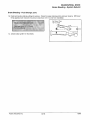
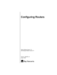
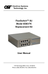
BRAKES/FINAL DRIVE
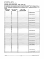
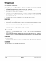
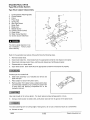
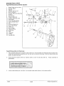
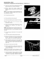
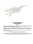
Jackshaft Speed vs. MPH Chart 7.05" Chaincase
Top Sprokect
25
23
23
23
22
22
20
21
19
19
18
18
17
Lower Sproket
41
39
40
41
40
41
39
41
39
40
40
41
41
Chain Length
72
70
70
70
70
70
68
70
68
68
68
68
68
Jackshaft
RPM
MILES PER HOUR
64;6'
6100
78.1
75.6
73.7
71.9
78.0
76.1
74.2
78.5
76.6
70.5
68.7
65.7
65.6
59;9
5.6.7
55,3
52.3"
62.4
60.9
57.7
56.2
53.1
64.5
62.9
59.5
58.1
54.9
66.5
64.8
61.4
59.9
56.6
6200
6300
80.7
:);' 7~.3 .·•
6500
83.2
80.5
75.1
73.3
t~:~A7~n; m~"·'· " .:~,·:·"· y' ~·:~<-r:J.·E·~· .':.-.~..~8~5.~8
:>
~~~83~.o~[l=+·~:::-::9~1: ·+-1'7: : 8~9;~ ·:•~ ir:'~: 6.:. ;: .; .·
.;;.
.. _..;;
..
.•
70.0
69.9
_.; .1' -+1·7: :72,:-:•;:·:~· i+:r•;: 21: ;:f.~ ··~mmr::~:-:::-··_.;;.-+. "":!El:6~s6~8~=:~&;-J-+IT~.·~6~ 3:-;.'*3:-'";.; :.,•, , .; . ; . J.J'ir: -:1·~ ;. ;·:; .~
_.;;.-+1%.::7"¥::-5'.-::1:!5%
...
• .;;;:
.•.
1_.;;.
•.
!.;;.···+':7::"::-':····.;;;':......:...t'
.
·6800 .
6900
88.4
85.5
83.3
81.3
79.7
77.8
74.3
74.2
70.6
68.8
65.2
63.6
60.1
7100
90.9
87.9
85.7
83.7
82.0
80.0
76.5
76.4
72.7
70.8
67.1
65.5
61.8
69.0
67.3
63.6
71.8::''::
93.5
7300
90.4
88.2
86.0
84.3
82.3
78.6
78.5
79.6 .
7500
96.1
92.9
90.6
88.4
86.6
84.5
80.8
98.6
95.4
93.0
90.7
88.9
86.8
82.9
74.7
175.7_ ::
72.8
73.8
80.7
76.7
74.8
70.9
69.2
65.3
76.8
72.8
71.0
67.1
h7600.
7700
7900
101.2
8100
103.7
•8200
.:
97.9
100.3
•_101.6
8300
106.3
8500
108.9
102.8
82.8
78.8
83.9./ .
79.8.
95.4
93.1
91.3
89.0
85.1
85.0
80.8
78.8
74.7
72.8
68.8
97.8
95.4
93.6
91.3
87.2
87.1
82.9
80.8
76.6
74.7
70.5
100.2
97.8
95.9
93.5
89.4
89.3
84.9
82.8
78.4
76.5
72.3
100.2
98.2
95.8
91.6
91.4
87.0
84.8
80.3
78.4
74.0
102.5
100.5
98.1
93.7
93.6
89.0
86.8
82.2
80.2
78.5
104.9
102.8
100.3
95.9
95.7
91.1
88.8
84.1
82.1
77.5
102.6
98.0
97.9
93.1
90.8
86.0
83.9
79.2
100.2
100.0
95.2
92.8
87.9
85.8
81.0
107.1
102.3
102.2
97.2
94.8
89.8
87.6
82.7
'i
71.4 •.. ;
104.() ... ;; JQf:
9100
9200
116.5
105.3
112.7
102.7
109.9
107.2
105.1
)106.3 .. ·.
··:•
119.1
9300
~:j
115.2
112.3
109.6
107.4
104.8
:j,10f!:~
·· ...
121.7
9500
103.7
117.7
114.7
111.9
109.7
81•. 9. -~··;-
.•
[110.9
9700
9900
:;)CJP()()..
10/98
.
124.2
120.2
117.1
114.3
112.1
109.3
104.5
104.4
99.3
96.8
91.7
89.4
84.5
126.8
122.6
119.6
116.6
114.4
111.6
106.6
106.5
101.3
98.8
93.6
91.3
86.2
i •
8.2
Polaris Industries Inc.
HYVO TM
BRAKES/FINAL DRIVE
Sprocket Part Numbers
HYVO Sprocket Part Numbers
TM
Top Sprockets For 3/4" HYVO
17T
3221084
18T
3221085
19T
3221086
20T
3221087
21T
3221088
22T
3221089
23T
3221090
24T
3221091
25T
3221092
TM
Drive Systems
HYVO ™ Drive Chain
Chain Length (Pitch)
Part Number
66P
3224071
68P
3224070
70P
3224069
Bottom Sprockets For 3/4" HYVO
Standard Bottom Sprockets
TM
Drive Systems
Reverse Sprockets
39T
3222105
40T
1341224
40T
3222094
41T
1341225
41T
3222095
Polaris Industries Inc.
8.3
10/98
BRAKES/FINAL DRIVE
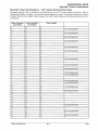
Sprocket I Chain Combinations
Sprocket I Chain Combinations - 6 5/8" Chain Case
Acceptable gearing I chain combinations are listed below for the 6.625" (center distance) chaincase. Do not use
this chart for models with 7.05" chaincase Refer to page 8.5 for 7.05" chaincase. Refer to Specifications section
of chapter 1 for chaincase center distance by mode. Combinations listed as "not recommended" should not be
installed.
Upper Sprocket
(#of Teeth}
16
16
16
16
16
17
17
17
17
17
18
18
18
18
18
19
19
19
19
19
20
20
20
20
20
21
21
21
21
21
22
22
22
22
22
23
23
23
23
23
24
24
24
25
25
25
10/98
Lower Sprocket
(#of Teeth}
35
37
39
40
41
35
37
39
40
41
35
37
39
40
41
35
37
39
40
41
35
37
39
40
41
35
37
39
40
41
35
37
39
40
41
35
37
39
40
41
39
40
41
39
40
41
Chain Length
(6.625 Chain Case)
62
64
64
66
66
62
64
64
66
66
64
64
66
66
66
64
64
66
66
66
64
66
66
66
68
64
66
66
68
68
64
66
68
68
68
66
66
68
68
68
68
68
70
68
70
70
NOT RECOMMENDED
NOT RECOMMENDED
NOT RECOMMENDED
NOT RECOMMENDED
NOT RECOMMENDED
NOT RECOMMENDED
NOT RECOMMENDED
NOT RECOMMENDED
NOT RECOMMENDED
NOT RECOMMENDED
NOT RECOMMENDED
NOT RECOMMENDED
NOT RECOMMENDED
NOT RECOMMENDED
NOT RECOMMENDED
NOT RECOMMENDED
8.4
Polaris Industries Inc.
BRAKES/FINAL DRIVE
Sprocket I Chain Combinations
Sprocket I Chain Combinations- 7.05" Center Distance Chain Case
Acceptable gearing I chain combinations are listed below for the 7.05" (center distance) chaincase. Refer to
Specifications section of chapter 1 for chaincase center distance by model. Combinations listed as "not recommended" should not be installed. Refer to page 8.4 for 6 5/8" (center distance) chaincase gearing/chain recommendations.
Upper Sprocket
(#of Teeth)
16
16
16
16
16
17
17
17
17
17
18
18
18
18
18
19
19
19
19
19
20
20
20
20
20
21
21
21
21
21
22
22
22
22
22
23
23
23
23
23
24
24
24
25
25
25
Lower Sprocket
(#of Teeth)
35
37
39
40
41
35
37
39
40
41
35
37
39
40
41
35
37
39
40
41
35
37
39
40
41
35
37
39
40
41
35
37
39
40
41
35
37
39
40
41
39
40
41
39
40
41
Polaris Industries Inc.
Chain Length
64
66
66
68
68
64
66
68
68
68
66
66
68
68
68
66
66
68
68
70
66
68
68
70
70
66
68
70
70
70
68
68
70
70
70
68
68
70
70
70
70
70
72
70
72
72
NOT RECOMMENDED
NOT RECOMMENDED
NOT RECOMMENDED
NOT RECOMMENDED
NOT RECOMMENDED
NOT RECOMMENDED
NOT RECOMMENDED
NOT RECOMMENDED
NOT RECOMMENDED
NOT RECOMMENDED
NOT RECOMMENDED
NOT RECOMMENDED
NOT RECOMMENDED
NOT RECOMMENDED
NOT RECOMMENDED
NOT RECOMMENDED
NOT RECOMMENDED
NOT RECOMMENDED
8.5
10/98
BRAKES/FINAL DRIVE
Specifications
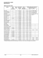
1999 Track Drive Data
Model
Drive
No. of
Drive
Type
Sprockets
Drive Shaft
Bearing
Lock
Drive
Sprocket
Diameter
DRIVE SPROCKET POSITION
Reference Page 8.7
A
8
Indy 340
Indy 340 Deluxe
2
2
3*
3*
Pressed
Pressed
6.94
6.94
7.48
12.32
7.48
Indy 340 Touring
2
3*
Pressed
6.94
7.48
12.32
12.32
2
3*
Pressed
6.94
7.48
12.32
2
2
2
2-wide
3*
3*
Pressed
Pressed
Pressed
6.94
6.94
6.94
7.48
7.48
12.32
12.32
7.48
2
2
2
3*
3*
3*
3*
3*
Pressed
Pressed
Pressed
Pressed
Pressed
Pressed
6.94
6.94
6.94
6.94
6.94
6.94
6.95
7.48
7.48
7.48
7.48
7.48
12.32
11.79
6.94
6.94
7.48
7.48
12.32
12.32
Indy Sport
Indy Sport Touring
Indy TranSport
Indy XCF
Indy XCR 440
Indy Trail
Indy Trail Touring
Indy Trail RMK
3*
3*
Indy Supersport
Indy 500
2
2
Indy Classic
2
2
3*
3*
Pressed
Pressed
Indy 500 RMK
Indy Classic Touring
D
All 1999 models,
sprocket positions
are measured to
sprocket hub and
not idler center. See
page 8.7.
12.32
12.32
12.32
12.32
12.32
2
3*
Pressed
6.94
7.48
12.32
Indy XLT Special
2-wide
3*
11.79
2-wide
3*
6.94
6.94
6.95
Indy XLT Classic
Pressed
Pressed
6.95
11.79
Indy XLT Touring
4
3*
Pressed
6.94
4.35
7.48
Indy 500 XC/SP
2 (wide)
3*
Pressed
6.94
6.95
11.79
Indy 600 XC/SP
2 (wide)
3*
6.94
6.95
11.79
Indy 700 XC/SP
Indy 600 RMK
2 (wide)
3*
Pressed
Pressed
6.94
6.95
2 (wide)
3*
6.94
Indy 700 RMK
2 (wide)
3*
Pressed
Pressed
6.94
6.95
6.95
11.79
11.79
Indy 700 SKS
2 (wide)
3*
Pressed
6.94
6.95
11.79
Indy 700 XCR
4
3*
Pressed
6.94
4.35
Indy 800 XCR
4
3*
Pressed
6.94
4-w'trak
4*
Pressed
6.94
Indy Widetrak LX
c
12.32
16.32
12.32
12.32
16.32
4.35
7.48
7.48
1.26
4.41
15.97
17.47
11.79
16.32
* Denotes driveshafts with press-fit bearings on left side (no lock collar) and flangette studs (welded).
10/98
8.6
Polaris Industries Inc.
BRAKES/FINAL DRIVE
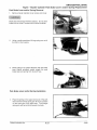
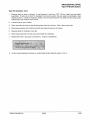
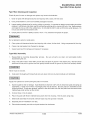
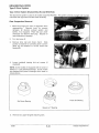
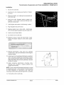
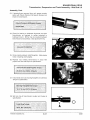
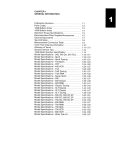
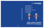
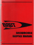
Drive Shaft Sprocket Installation Tips
Driveshaft Sprocket Installation
• All models, except WideTraks, have a longer spline on the chaincase end of the jackshaft and drive
shaft.
• Sprockets must be started from the splined end of the shaft.
• To ensure proper sprocket tooth alignment, be sure the vendor logos are oriented in the same position
on all sprockets.
• Drive shaft sprocket positions are measured to sprocket hub edge. Not idler center.
• For measurements shown below (A-D) see page 8.6.
~
~
Direction of press of shaft
Direction of press of shaft
Logo Orientation
~---~- s-~---l
•
-
-A~
I
Use straight edge against
sprocket hub
2 Drive Sprocket
~
Square
4 Drive Sprocket
~
Direction of press of shaft
r-----s--------~
Left Side
WideTrak LX
2 Drive Sprocket - Wide
Coupler
NOTE: When installing drive sprockets, all dimensions are indicated as the shaft is being pressed onto the
sprockets. Mark the shaft with a Dykem™ and a machinist scribe, or a fine line permanent marker for proper
sprocket placement. Allow mark to thoroughly dry prior to assembly. Verify proper placement using a straight
edge and square on sprocket hub and shaft as shown. On WideTraks, measure from coupler as shown.
Polaris Industries Inc.
8.7
10/98
BRAKES/FINAL DRIVE
Track Specifications
1999 Track
Model
Length x Width
Pattern
Lug
Height
Wheels
Bogie/
Idler
121 X 15"
Block
.66"
4/2
133.5 X 15"
Lightning
.82"
6/3
121 X 15"
Block
.71"
4/2
133.5 X 15"
Lightning
.82"
6/3
Indy TranSport
141 X 15"
Wiper
1.125"
8/3
Indy XCF
121 X 15"
New Yokohama
.82"
6/4
Indy Super Sport
121 X 15"
Lightning
.82"
6/3
Indy 340/340 Deluxe
Indy 340 Touring
Indy Sport
Indy Sport Touring
Indy 440 XCR
121 X 15"
Lightning
.82"
6/4
Indy WideTrak LX
156 X 20"
Shockwave
1.00"
8/4
Indy Trail
121 X 15"
Lightning
.82"
6/3
133.5 X 15"
Lightning
.82"
6/3
Indy Trail RMK
136 X 15"
Deep Lug
1.25"
4/3
Indy 500
121 X 15"
Lightning
.82"
6/3
133.5 X 15"
Deep Lug
1.25"
4/3
6/3
Indy Trail Touring
Indy 500 RMK
121 X 15"
Lightning
.82"
133.5 X 15"
Lightning
.82"
6/3
Indy 500 XC/SP
121 X 15"
Shockwave
.82"
6/4
Indy XLT Classic
121 X 15"
Shockwave
.82"
6/3
Indy XLTSpecial
121 X 15"
Shockwave
.82"
6/4
Indy XLT Touring
133.5 X 15"
Lightning
.82"
6/3
Indy 600 XC/SP
121 X 15"
Shockwave
.91"
6/4
Indy 600 RMK 1.75" Track
136 X 15"
Deep Lug
1.75"
4/3
Indy 600 RMK 2.00" Track
136 X 15"
Deep Lug
2.00"
4/3
Indy 700 XC/SP
121 X 15"
Shockwave
.91"
6/4
Indy 700 SKS
136x15"
Deep Lug
1.25"
6/3
Indy 700 RMK 1.75" Track
136 X 15"
Deep Lug
1.75"
4/3
Indy 700 RMK 2.00" Track
136 X 15"
Deep Lug
2.00"
4/3
Indy 700 XCR
121 X 15"
Shockwave
.91"
6/4
Indy 800 XCR
121 X 15"
Shockwave
.91"
6/4
Indy 500 Classic
Indy Classic Touring
10/98
8.8
Polaris Industries Inc.
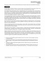
BRAKES/FINAL DRIVE
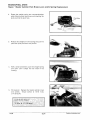
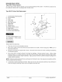
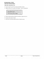
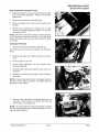
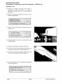
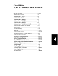
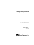
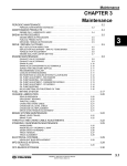
Hydraulic Brake System Operation
End
View
A
\:f)
E
F
A
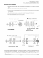
0----The Polaris snowmobile hydraulic brake system consists of the following components or assemblies: brake lever,
master cylinder, hydraulic hose, brake caliper (slave cylinder), brake pads, and a brake disc which is secured to
the drive line.
When the hand activated brake lever (A) is applied, it contacts a piston (B) within the master cylinder. As the
master cylinder piston moves inward it closes a small opening called a compensating port (C) within the cylinder
and starts to build pressure within the brake system. As the pressure within the system is increased, the piston (D)
located in the brake caliper moves outward and applies pressure to the moveable brake pad. This pad contacts
the brake disc, moves the caliper in its floating bracket and pulls the stationary pad into the brake disc. As the lever
pressure is increased, the braking effect is increased.
The friction applied to the brake pads will cause the pads to wear. As the pads wear, the piston within the caliper
self-adjusts and moves further outward.
Brake fluid level is critical to proper system operation. A low fluid level allows air to enter the system causing the
brakestofeelspong~
Compensating Port
Located within the master cylinder is a small compensating port (C) which is opened and closed by the master
cylinder piston assembly. The port is open when the brake lever is released and the piston is outward. As the
temperature within the hydraulic system changes, this port compensates for fluid expansion caused by heat, or
contraction caused by cooling. During system service, be sure this port is open. Due to the high temperatures
created within the system during heavy braking, it is very important that the master cylinder reservoir have
adequate space to allow for the brake fluid to expand. Master cylinder reservoirs should be filled to the top of the
fluid level mark on the inside of the reservoir, 1/4"- 5/16" (.6- .8 em) below lip of reservoir opening.
A
WARNING
Never overfill the reservoir. This could alter brake function, resulting in system component damage or sever
personal injury or death.
This system also incorporates a diaphragm (E) as part of the cover gasket and a vent port (F) located between the
gasket and the cover. The combination diaphragm and vent allow for the air above the fluid to equalize pressure
as the fluid expands or contracts. Be sure the vent is open and allowed to function. If the reservoir is overfilled or
the diaphragm vent is plugged, the expanding fluid may build pressure in the brake system and lead to brake
failure.
Polaris Industries Inc.
8.9
10/98
BRAKES/FINAL DRIVE
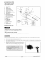
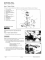
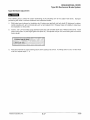
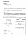
Type 3 Master Cylinder
Type 3 Master Cylinder
1.
2.
3.
4.
5.
6.
7.
8.
9.
10.
11.
12.
13.
14.
15.
16.
17.
18.
19.
Cover Screw
Cover
Cover Gasket
Cylinder Housing
Brake Lever Bushing
Brake Lever
Park Lever Return Spring
Pivot Bolt Nut
Park Lever
Park Lever Pivot Bolt
Park Lever Pivot Bushing
Spring Seat Washer
Compression Spring
U-Pack Seal
Piston
0-Ring Seal
Clamp Bolt
Attaching Clamp
Lever Pivot Bolt
20. Baffle
21. Baffle Washer
Optional
at customer
request
0
PARK BRAKE
LOCK
RELEASE BEFORE
DRIVING OR BRAKE
SYSTEM FAILURE
OR FIRE MAY
RESULT. APPLY
BRAKE LEVER
TO RELEASE.
Park Brake Lever Lock
A
WARNING
Release park brake lock before driving or brake system failure or fire may result. Apply brake lever to release.
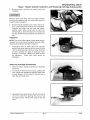
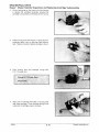
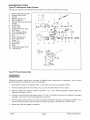
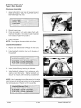
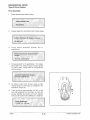
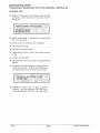
Type 3 Master Cylinder Removal
1.
Position clean shop cloths to catch spilled fluid and remove brake hose.
Brake fluid will damage finished surfaces. Do not allow brake fluid to come in contact with finished surfaces.
2.
Remove brake clamp attaching bolts (Item 17).
3.
Remove park brake lever (Item 9) and brake master cylinder lever (Item 6), noting position of bushing, spring,
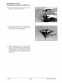
etc., for proper reassembly.
4.
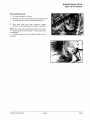
Using the master cylinder service tool, position push rod
through small hole in spring seat washer (Item 12) as
shown. Remove piston assembly, spring and washer.
Mast~r Cyli~d~~ Service Tool Kit
PN 2870962 .
..'-/
10/98
'
8.10
Polaris Industries Inc.
BRAKES/FINAL DRIVE
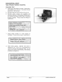
Type 3 Master Cylinder Inspection and Assembly
Inspection
NOTE: Due to the critical nature of these parts and procedures, be sure you have thoroughly read and understand Hydraulic Brake Operation, page 8.9.
1.
Thoroughly clean all brake parts with isopropyl
alcohol. Inspect piston for wear, scratches, or
corrosion.
Check master cylinder bore for
scratches, score marks, or corrosion and replace
any worn or damaged parts.
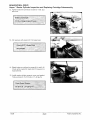
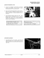
Assembly
1.
2.
Always replace 0-Ring seal, U-pack seal and
cover gasket (diaphragm) upon reassembly. Use
only genuine Polaris service parts.
Apply clean DOT 3 brake fluid on piston, piston
seals and cylinder bore. Install seals onto piston
positioning U-pack seal lip (A) towards spring.
Snap spring into place on piston.
Polaris DOT 3 Brake Fluid.:
PN 2870990
..
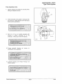
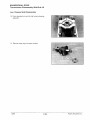
3.
Install piston assembly into master cylinder service
tool until U-pack seal is covered by tool as shown.
NOTE: This tool is used to guide the seal lip into the
cylinder bore without damage.
Polaris Industries Inc.
8.11
10/98
BRAKES/FINAL DRIVE
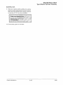
Type 3 Master Cylinder Assembly
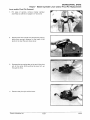
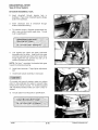
Assembly, Cont.
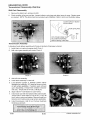
4.
Install spring seat washer into bore. Insert piston,
still installed in tool, into bore. Push piston through
special tool. Remove tool.
5.
Reinstall brake lever with bushing, bolt and nut.
6.
Reinstall master cylinder onto handlebar and
reconnect brake line. Partially insert fittings (one to
two threads) and apply Loctite™ 242 to remaining
threads of fittings. Torque brake line fittings to
specification.
Brake Line Fitting Torque Master Cylinder End - Finger tight
plus 2 turns
Caliper End 12-14 ft. lbs. (1.66 -1.93 kg-m)
7.
Adjust master cylinder to a level position on
handlebar. Torque clamp screws to specification.
Master Cylinder Clamp Torque 45-55 in.lbs. (.52- .63 kg-m)
8.
Bleed brake system.
Maintain fluid level in
reservoir at 1/4"- 5/16" (.6- .8 em) below lip of
reservoir opening while bleeding brakes. Do not
allow air into system while bleeding. See bleeding
procedure on page 8.14.
Master Cylinder Fluid Level
1/4"'- 5/16" (.6- .8 em) below
top of master cylinder
10/98
8.12
Polaris Industries Inc.
BRAKES/FINAL DRIVE
Type 3 Master Cylinder Assembly
Assembly, Cont.
9.
Field test machine before putting into service.
Check for proper braking action and lever reserve.
With lever firmly applied, lever reserve should be
no less than 1/2" (1.3 em) from handlebar.
Brake Lever Reserve Limit
Not less than 1/2" (1.3 em)
from handlebar
10. Check brake system for fluid leaks.
Polaris Industries Inc.
8.13
10/98
BRAKES/FINAL DRIVE
Brake Bleeding - Fluid Change
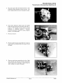
Brake Bleeding - Fluid Change
This procedure should be used to change fluid or bleed brakes during regular maintenance, or after complete
brake service. Brake fluid may damage painted or plastic surfaces. Take care not to spill, and wipe up any spills
immediately. Cover parts to avoid damage.
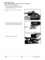
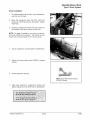
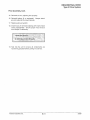
1.
Clean reservoir cover thoroughly.
2.
Remove screws, cover, and diaphragm from
reservoir.
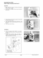
3.
Inspect vent slots (A) in cover and remove any
debris or blockage.
4.
If changing fluid, remove fluid from reservoir with a
Mity Vac™ pump or similar tool.
NOTE: Do not remove brake lever when reservoir fluid
level is low.
c
D
5.
Add brake fluid to within 1/4-5/16" (.6-.8 em) of
reservoir top.
6.
lnstall.a box end wrench on caliper bleeder screw fitting. Attach a clean, clear hose to fitting and place the
other end in a clean container. Be sure the hose fits tightly on fitting.
NOTE: Fluid may be forced from compensation port (B) when brake lever is pumped. Place diaphragm (C) in
reservoir to prevent spills. Do not install cover.
7.
Slowly pump lever (D) until pressure builds and holds.
8.
While maintaining lever pressure, open bleeder screw. Close bleeder screw and release brake lever. Do not
release lever before bleeder screw .is tight or air may be drawn into caliper.
9.
Repeat procedure until clean fluid appears in bleeder hose and all air has been purged. Add fluid as
necessary to maintain level in reservoir.
Maintain at least 1/2" (1.27 em) of brake fluid in the reservoir to prevent air from entering the master cylinder.
10. Tighten bleeder screw securely and remove bleeder hose.
11. Add brake fluid to the proper level.
12. Install diaphragm, cover, and screws. Tighten screws to specification.
10/98
8.14
Polaris Industries Inc.
BRAKES/FINAL DRIVE
Brake Bleeding- System Rebuild
Brake Bleeding - Fluid Change, Cont.
13. Field test machine before putting into service. Check for proper braking action and lever reserve. With lever
firmly applied, lever reserve should be no less than 1/2" (1.3 em) from handlebar.
No Closer Than
1/2" (1.3 em)
14. Check brake system for fluid leaks.
Polaris Industries Inc.
8.15
10/98
BRAKES/FINAL DRIVE
Hayes Master Cylinder
TM
Hayes ™ Master Cylinder
The Hayes'" brake is standard on all 1999 Gen II snowmobiles except for Widetrak LX and TranSport.
1.
2.
3.
4.
5.
6.
7.
8.
9.
10.
11.
12.
13.
14.
Cover Screw Kit
Cover Asm. Kit (Incl. 1,3)
Cover Gasket
Parking Lever Spring
Master Cylinder Assembly
Screw
Lever and Pivot Pin Kit
Screw
Body/Reservoir Clamp Kit
Brakelight Switch
Cartridge Kit
LH Control Asm
Pivot Pin Kit
Parking Lever and Spring Kit
2
3
14
12
5
Park Brake Lever Lock
A
WARNING
Release park brake lock before driving or brake system failure or fire may result. Apply brake lever to release.
Hayes ™ Master Cylinder Removal
1.
Position clean shop cloths to catch spilled fluid.
Brake fluid will damage finished surfaces. Do not allow brake
fluid to come in contact with finished surfaces.
2.
Remove the handlebar protector pad from the outlet end
of the handlebar master cylinder to access the brake fluid
line connector.
•Remove
•Remove
•Remove
•Remove
handlebar cover strips
two screws
holding clip in front of cover
handlebar pad
3.
Loosen the connector approximately 1/4 to 1/2 turn.
4.
Loosen and remove the four switch pack and handlebar
master cylinder mounting screws. Put screws aside for
later installation.
10/98
8.16
Polaris Industries Inc.
Hayes
5.
TM
BRAKES/FINAL DRIVE
Master Cylinder Inspection and Replacing Cartridge Subassembly
Remove master cylinder from switch pack and
handlebar.
Remove switch pack wires from the master cylinder
housing with extreme care and note where they are
routed for later installation.
6.
Remove master cylinder cover screws and cover.
Pour out the fluid in the resrevoir into a container.
Unscrew the brake fluid line from the master
cylinder outlet using a shop cloth to catch the
remaining fluid. Drain the fluid from the brake line
into the aforementioned container and discard the
fluid.
Inspection
NOTE: Due to the critical nature of these parts and procedures, be sure you have thoroughly read and understand Hydraulic Brake Operation, page 8.9.
1.
Thoroughly clean all brake parts with isopropyl
alcohol and either wipe dry with a clean lint free
cloth or lightly blow dry with an air hose. Examine
all parts carefully for signs of excessive wear,
damage, or corrosion. Replace any parts found to
be damaged.
Check park lever spring for
breakage.
Replacing Cartridge Subassembly
1.
2.
3.
Remove master cylinder assembly as described
previously.
To remove the lever from the housing, squeeze the
lever handle and actuate the parking brake lever
enough distance for the head of the pivot pin to
clear the park brake lever.
Squeeze the two spring tabs on the end of the pivot
pin at the same time pushing the pivot pin up
throught the hole. Remove the pivot pin and the
lever.
Polaris Industries Inc.
8.17
10/98
BRAKES/FINAL DRIVE
Hayes Master Cylinder Inspection and Replacing Cartridge Subassembly
1M
4.
Lift the housing tab on the outlet end of the housing
to release the cartridge assembly, allowing the
cartridge to be pushed out the back of the housing.
5.
Clean housing bore with alcohol. Inspect bore for
scratches, dents, cuts, or digs that might cause a
leak. Replace housing if severe damage is found.
6.
Paint housing bore and cartridge o-rings with
D.O.T. 3 brake fluid.
Polaris DOT 3 Brake Fluid
PN 2870990
7.
Align slots in cartridge with tabs in housing bore
and insert cartridge. Push cartridge through until
outlet end of cartridge snaps into place.
10/98
8.18
Polaris Industries Inc.
BRAKES/FINAL DRIVE
Hayes"" Master Cylinder Inspection and Replacing Cartridge Subassembly
8.
Install the lever and pivot pin by actuating the
parking brake lever enough distance for the head of
the pivot pin to clear the park brake lever.
9.
Align the lever pivot hole with the housing pivot
hole. Squeeze the two spring tabs on the end of the
pivot pin at the same time pushing the pivot pin
down through the pivot hole until the pivot pin snaps
into place.
10. Apply thread sealant, install brake line and tighten
snug.
11. Mount the master cylinder and switch pack to the
handlebars making sure the wires are not pinched
or twisted.
NOTE: Start all four screws prior to tightening. Tighten
tip two screws first, followed by bottom two. Do not
over tighten. This will create a gap approximately
.050-.1 00" between LH control and master cylinder at
the bottom of the assembly. There should not be a gap
at the top when correct tightening/torque sequence
has been followed. Torque to 24-28 in.lbs.(.27-.32
kg-m).
Master Cylinder Control Torque 24-28 in. lb. (27-32 kg-m)
Polaris Industries Inc.
8.19
10/98
BRAKES/FINAL DRIVE
Hayes Master Cylinder Inspection and Replacing Cartridge Subassembly
TM
12. Tighten brake line connector at outlet to 1 ft.lb. plus
two turns.
Brake Line Torque 1 ft. lb. (.14 kg-m) plus 2 turns
13. Fill reservoir with clean D.O.T. 3 brake fluid.
Polaris DOT 3 Brake Fluid
PN 2870990
14. Bleed brakes as outlined on pages 8.14 and 8.15.
Check entire systemfor leaks and fill reservoir to
fluid level line.
15. Install master cylinder reservoir cover and gasket.
Torque screws to 15-18 in.lbs. (.17-.20 kg-m.)
Cover Screw Torque -
15-18 in. lb. (.17-.20 kg-:m) ·
10/98
8.20
Polaris Industries Inc.
Hayes
TM
BRAKES/FINAL DRIVE
Master Cylinder Lever and/or Pivot Pin Replacement
Lever and/or Pivot Pin Removal
1.
For ease of service, remove master cylinder
assembly as outlined on pages 8.17 and 8.18.
2.
Squeeze the lever handle and actuate the parking
brake lever enough distance for the head of the
pivot pin to clear the park brake lever.
3.
Squeeze the two spring tabs on the end of the pivot
pin at the same time pushing the pivot pin up
through the hole.
4.
Remove the pivot pin and the lever.
Polaris Industries Inc.
8.21
10/98
BRAKES/FINAL DRIVE
Hayes ™ Master Cylinder Lever and/or Pivot Pin Replacement
Lever and/or Pivot Pin Installation
1.
Install the new lever by actuating the parking brake
lever enough distance for the head of the pivot pin
to clear the park brake lever.
2.
Align the lever pivot hole with the housing pivot
hole.
3.
Squeeze the two spring tabs on the end of the pivot
pin at the same time pushing the pivot pin down
through the hole until the pivot pin snaps into place.
4.
Reinstall master cylinder assembly.
10/98
8.22
Polaris Industries Inc.
Hayes
1M
BRAKES/FINAL DRIVE
Master Cylinder Park Brake Lever and/or Spring Replacement
Park Brake Lever and/or Spring Removal
1.
Remove master cylinder cover screws and cover.
Brake fluid will damage finished surfaces. Do not allow
brake fluid to come in contact with finished surfaces.
2.
Using a small screwdriver, lift long spring arm out of
its notch in the housing.
3.
While pulling in an upward direction with the brake
lever slightly activated, gently wiggle the park
brake lever and spring from its pivot hole.
Park Brake Lever and/or Spring Installation
1.
Place the spring on the upper pivot post of the park
lever with the formed spring arm fit into its position
on the outer part of the park lever. The straight
spring arm will be pointing towards the back.
Polaris Industries Inc.
8.23
10/98
BRAKES/FINAL DRIVE
Hayes Master Cylinder Park Brake Lever and/or Spring Replacement
TM
2.
Rotate the straight spring arm counterclockwise
while tilting the park lever down and inserting the
pivot post into the pivot hole.
3.
Release the straight arm of the spring and push the
park lever pivot post down into position.
4.
With a small screwdriver, push the straight spring
arm down until it snaps into the notch in the
housing.
5.
Fill reservoir. Replace the master cylinder cover
and screws. Torque screws to 15-18 in.lbs.
(.17-.20 kg-m).
Cover Screw Torque 15-18 in. lb. (.17-.20 kg-m)
10/98
8.24
Polaris Industries Inc.
BRAKES/FINAL DRIVE
Type H4 Brake System
The Type H4 system is a hydraulic brake. The caliper assembly is mounted on the chaincase, which allows ease
of brake pad and caliper service. Measure brake pads from the back of the backing plate to the surface of the
friction material as shown in illustration.
NOTE: Replace pads when worn beyond service limit.
Minimum Pad
Thickness
.250"
(6.35mm)
Type H4 Friction Pad Replacement
1.
2.
3.
4.
5.
6.
7.
8.
9.
10.
Carrier Bracket Attaching Bolts
Carrier Bracket
Piston
Piston Seal
Spring Clip
Stop Light Switch
Brake Pads
Brake Line
Bleeder Screw
Caliper
11. Rope Guide
A"WARNING
2
The rider's safety depends on correct installation. Follow procedures carefully.
Protect eyes from brake fluid.
1.
Clean any dirt from mount
bracket and bolts.
Brake
cleaner may be used to aid in
cleaning of components.
2.
With a 9/16" socket, remove two 3/8 hex bolts and washers from bracket. Remove rope guide. NOTE: Do not
disconnect brake line.
3.
Lift bracket and brake assembly off vehicle. Remove all dirt from caliper assembly using brake cleaner and
clean shop cloths.
4.
Use a drop cloth to protect surfaces from brake fluid spillage. Remove reservoir cover from master cylinder
assembly. Using a large hardwood dowel, or a C clamp vise grip on the center of the old pads, apply pressure
toward the caliper piston. Compress piston back into caliper assembly. Apply pressure slowly to prevent
excessive spillage from master cylinder assembly.
NOTE: Pushing the piston back into the bore will cause the fluid level to rise in the reservoir and possibly overflow.
Remove excess fluid and discard.
Piston must not be forced back into the caliper at an angle or bore damage may occur.
5.
Slide caliper and brake pads out of bracket. Discard old pads and clips.
NOTE: Pad and holders must be replaced as a set.
Polaris Industries Inc.
8.25
10/98
BRAKES/FINAL DRIVE
Type H4 Brake System
Type H4 Friction Pad Replacement, Cont.
6.
7.
Place new pads with friction material facing each other into housing. Hold in place using clips. See illustration
on page 8.25.
Slide brake assembly into bracket until both clips snap into grooves in bracket.
8.
9.
Clean brake mount on top of chaincase.
Separate pads for installation over disc. If brake assembly does not slide easily over the disc with loose pads,
the piston is not compressed far enough into the caliper. Caliper assembly must fit freely onto disc and
chaincase.
10. Replace 3/8 bolts, washers, and rope guide. Torque to specification.
11. Actuate brake several times to set brake pads to proper operating position.
12. Check for proper fluid level in master cylinder and replace cover Torque cover bolts to specification.
13. Inspect entire system for leaks and repair if necessary.
14. Field test at low speeds and verify proper brake action. If pads drag on disc, check caliper and pad assembly.
10/98
8.26
Polaris Industries Inc.
BRAKES/FINAL DRIVE
Type H4 Brake System
Type H4 Caliper Disassembly
1.
2.
3.
4.
5.
6.
7.
8.
9.
10.
11.
A
Carrier Bracket Attaching Bolts
Carrier Bracket
Piston
Piston Seal
Spring Clip
Stop Light Switch
Brake Pads
Brake Line
Bleeder Screw
Caliper
Rope Guide
WARNING
The rider's safety depends on correct installation. Follow procedures carefully.
Refer to the exploded view above while performing the following steps.
1. Remove bracket bolts.
2. Disconnect brake line. Drain brake fluid into appropriate container and dispose of properly.
3. Disassemble on a clean bench.
4. Open bleeder screw and drain brake fluid from caliper assembly into appropriate container. Dispose of
properly.
Protect eyes from brake fluid at all times.
5.
6.
7.
Slide brake assembly out of bracket and remove old pads and clips.
Place caliper on bench with piston down.
Remove piston from caliper using a caliper piston pliers (commercially available) or by covering the piston with
a shop cloth and applying compressed air to the hydraulic inlet port.
Use only enough air to remove piston. Too much pressure may damage piston or bore.
8.
Using a small wooden or plastic stick, work piston seal out from its groove in the piston bore.
To avoid scratching bore or burring edge of seal groove, do not use a metal tool such as a screwdriver.
9.
Discard old seal.
Polaris Industries Inc.
8.27
10/98
BRAKES/FINAL DRIVE
Type H4 Brake System
Type H4 Cleaning and Inspection
Check all parts for wear or damage and replace as required. Always replace caliper piston seal and dust seal
(where applicable).
1.
Clean all parts with denatured alcohol and wipe dry with a clean, lint free cloth.
2.
Using compressed air, blow out the drilled passages and piston bore. Be sure piston seal groove is thoroughly
clean and free from corrosion or brake fluid build up.
3.
Inspect piston bore for scoring, pitting or corrosion. A corroded or deeply scored casting should be replaced.
Light scores and stains may be removed by polishing with a crocus cloth only. Use finger pressure and rotate
the crocus cloth in the cylinder bore. Do not slide the cloth in and out of the bore under pressure. Do not use
any other kind of abrasive cloth.
4.
Check piston to see if it is pitted, scored or worn. If so, discard and replace the piston.
Do not attempt to polish or sand piston.
5.
Clean piston with denatured alcohol and wipe dry with a clean, lint free cloth. Using compressed air, blow dry.
6.
Check inlet and bleeder hole threads for damage. Be sure bleeder screw is clear.
7.
Inspect brake line seat for damage and replace caliper if necessary.
Type H4 Assembly
1.
Reassemble by reversing disassembly process.
reassembling the unit.
Be sure all parts are clean and serviceable before
2.
Coat a new piston seal in clean DOT 3 brake fluid and place in groove in the caliper piston bore. Seal should be
positioned at one point in groove and then gently worked around the groove by hand until properly seated.
Never reuse an old seal.
3.
Coat piston thoroughly with brake fluid and work down into bore carefully with a rotating motion until bottomed.
Apply even pressure to avoid cocking the piston in the bore.
10/98
8.28
Polaris Industries Inc.
BRAKES/FINAL DRIVE
Type H4 Brake System
Type H4 Assembly, Cont.
1.
Examine pads for wear or damage. If pad thickness is less than 1/32" (.08 em) install new pad holder
assemblies. If pads are not worn or damaged, they may be reused. Be sure pads are reinstalled in their
original positions. If pads are replaced, replace in sets and make sure the new pads have the same friction
material type code number as the old set.
2.
Connect hose or line to caliper.
3.
Place new pads with friction material facing each other into housing. Hold in place using clips.
4.
Slide brake assembly into bracket until both clips snap into grooves in bracket.
5.
Separate pads for installation over disc.
6.
Place brake assembly over disc and push bracket into chaincase.
7.
Replace 3/8" bolts, rope guide, and washers. Torque to specification.
8.
Perform brake bleeding procedure as outlined after System Rebuild, page 8.14-8.15.
Polaris Industries Inc.
8.29
10/98
BRAKES/FINAL DRIVE
Type HSLC Brake System
The Type H5LC system, like the Type H4, is a top mounted hydraulic brake system. The difference between the
two systems is the the H5LC is equipped with a brake cooler.
Type HSLC Friction Pad Replacement
1.
2.
3.
4.
5.
6.
7.
8.
9.
10.
11.
12.
13.
A
Carrier Bracket Attaching Bolts
Carrier Bracket
Piston
Piston Seal
Spring Clip
Stop Light Switch
Brake Pads
Brake Line
Bleeder Screw
Caliper (Liquid Cooled)
Rope Guide
Water Cooler Manifold
Screws (Cooler Manifold)
2
WARNING
The rider's safety depends on correct installation. Follow procedures carefully.
I·
7
CAUTiON:'·!
Protect eyes from brake fluid.
1.
2.
Clean any dirt from mount bracket and bolts.
With a 9/16" socket, remove two 3/8 hex bolts and washers from bracket. Remove rope guide. NOTE: Do not
disconnect brake line.
3.
Remove hose clamp from engine side of cooler. Twist and remove hose from cooler, catching and disposing
of antifreeze properly.
4.
Use a drop cloth to protect surfaces from brake fluid spillage. Remove reservoir cover. Using a large
hardwood dowel, or a C clamp vise grip on the center of the old pads, apply pressure toward the caliper piston.
Compress piston back into caliper assembly. Apply pressure slowly to prevent excessive spillage from
master cylinder assembly.
NOTE: Pushing the piston back into the bore will cause the fluid level to rise in the reservoir and possibly overflow.
Remove excess fluid and discard.
5.
Lift bracket and brake assembly off vehicle. Raise open end of cooler and pad assembly to trap antifreeze in
cooler and plug the opening of both cooler and engine hose open end.
10/98
8.30
Polaris Industries Inc.
BRAKES/FINAL DRIVE
Type HSLC Brake System
Type HSLC Friction Pad Replacement, Cont.
6.
Place new pads with friction material facing each other into housing. Hold in place using clips. See illustration
above.
7.
Slide brake assembly into bracket until both clips snap into grooves in bracket.
8.
Clean top of chaincase where brake mounts.
9.
Separate pads for installation over disc. If brake assembly does not slide easily over the disc with loose pads
the piston is not compressed far enough into the caliper. The caliper assembly must fit freely onto the disc and
chaincase.
10. Remove plugs. Install coolant hose and clamp on cooler assembly.
11. Replace 3/8" bolts, washers, and rope guide. Torque to specification.
12. Actuate brake several times to set brake pads to proper operating position.
13. Check for proper fluid level in master cylinder and replace cover. Torque to specification.
14. Be sure to bleed coolant system as outlined in Engine section.
15. Bleed brake system as outlined on pages 8.14-8.15.
16. Field test at low speeds before putting into regular service.
Polaris Industries Inc.
8.31
10/98
BRAKES/FINAL DRIVE
Type HSLC Brake System
Type HSLC Caliper Disassembly
Carrier Bracket Attaching Bolts
Carrier Bracket
Piston
Piston Seal
Spring Clip
Stop Light Switch
Brake Pads
Brake Line
Bleeder Screw
Caliper (Liquid Cooled)
11. Rope Guide
12. Water Cooler Manifold
13. Screws (Cooler Manifold)
1.
2.
3.
4.
5.
6.
7.
8.
9.
10.
A
2
WARNING
The rider's safety depends on correct installation. Follow procedures carefully.
Refer to the exploded view above while performing the following steps.
2.
3.
Remove bracket bolts.
Disconnect brake line. Drain brake fluid into appropriate container and dispose of properly.
Disconnect and plug coolant lines, catching and disposing of antifreeze properly.
4.
5.
Disassemble on a clean bench.
Open bleed screw. Drain brake fluid into appropriate container and dispose of properly.
1.
Protect eyes from brake fluid.
6. Slide brake assembly out of bracket and remove old
pads and clips.
7. Place caliper on bench with piston down.
8.
Remove piston from caliper using a caliper piston pliers
(commercially available) or by covering the piston with
a shop cloth and applying compressed air to the
hydraulic inlet port.
Use only enough air to remove piston. Too much pressure may damage piston or bore.
9.
Using a small wooden or plastic stick, work piston seal out from its groove in the piston bore.
To avoid scratching bore or burring edge of seal groove, do not use a metal tool such as a screwdriver.
10. Discard old seal.
10/98
8.32
Polaris Industries Inc.
BRAKES/FINAL DRIVE
Type HSLC Brake System
Type HSLC Cleaning and Inspection
Check all parts for wear or damage and replace any found to be defective.
1.
Clean all parts with denatured alcohol and wipe dry with a clean, lint free cloth.
2.
Using compressed air, blow out the drilled passages and bores.
3.
Inspect casting cylinder bore for scoring, pitting or corrosion. A corroded or deeply scored casting should be
replaced. Light scores and stains may be removed by polishing with a crocus cloth only. Use finger pressure
and rotate the crocus cloth in the cylinder bore. Do not slide the cloth in and out of the bore under pressure. Do
not use any other kind of abrasive cloth.
4.
Check piston to see if it is pitted, scored or worn. If so, discard and replace the piston.
Do not attempt to polish or sand piston.
5.
Clean piston with denatured alcohol and wipe dry with a clean, lint free cloth. Using compressed air, blow dry.
6.
Check inlet and bleeder hole threads for damage.
7.
Inspect seat insert for damage and replace if necessary.
Type HSLC Assembly
1.
Reassemble by reversing disassembly process.
reassembling the unit.
Be sure all parts are clean and serviceable before
2.
Coat a new piston seal in clean DOT 3 brake fluid and place in groove in the caliper bore. Seal should be
positioned at one point in groove and then gently worked around the groove by hand until properly seated.
Never reuse an old seal.
3.
Coat piston thoroughly with brake fluid and work down into bore by hand carefully until bottomed.
Apply even pressure to avoid cocking the piston in the bore.
4.
Examine pads for wear or damage. If pad thickness is less than 1/32" (.08 em) install new pads and spring clip
assemblies. If pads are not worn or damaged, they may be reused. Be sure pads are reinstalled in their
original positions. If pads are replaced, replace in sets and make sure the new pads have the same friction
material type code number as the old set.
5.
Connect hose or line to caliper.
6.
Place new pads with friction material facing each other into housing. Hold in place using clips.
7.
Slide brake assembly into bracket until both clips snap into grooves in bracket.
8.
Separate pads for installation over disc.
9.
Place brake assembly over disc and push bracket into chaincase.
Polaris Industries Inc.
8.33
10/98
BRAKES/FINAL DRIVE
Type HSLC Brake System
Type HSLC Assembly, Cont.
10. Install coolant lines and hose clamps and tighten securely.
11. Replace 3/8" bolts, rope guide, and washers. Torque to specification .
. Caliper Bolt Torque<
25-30 ft. lbs. (3.45-4.14 kg-m)
12. Perform brake bleeding procedure as outlined on pages 8.14-8.15.
13. Inspect entire system for leaks.
14. Field test at low speeds before putting into regular service.
10/98
8.34
Polaris Industries Inc.
BRAKES/FINAL DRIVE
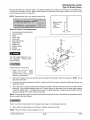
Type M3 Mechanical Brake System
The Type M3 system is the mechanical brake system used only on Indy 340 models.
1.
2.
3.
4.
5.
6.
7.
8.
9.
10.
11.
12.
13.
14.
15.
16.
17.
18.
19.
20.
21.
22.
23.
24.
Brake Cable and Jam Nuts
Bracket, Brake
Washer
Washer, Spring Lock
Bolt, Top Mount
Bracket, Brake Top Mounting
Bushing
Nut, Bi-Lock
Spacer, Alignment
Caliper, Stationary, Cast
Pad, Brake
Puck, Moveable Brake
Spring, Brake Return
Nut
Bushing, Brake Arm
Bolt, Cable Swivel
Clevis, LT
Bolt, Caliper
Retaining Ring
Brake Disc
Seal
Jackshaft
0-Ring
Adjuster Bolt
~1
18
24
7
B
A
5
6
/
C
D
8
12
11
Type M3 Brake Disassembly
Whenever inspection reveals worn, damaged or defective parts, replacement is necessary in order to avoid
serious damage to the machine or injury to the operator.
1.
Open adjuster bolt jam nut locking tab (A). Loosen jam nut and remove adjuster bolt (B).
2.
Remove actuating lever (C) and return spring. Do not detach cable from lever arm.
3.
Remove top mount bracket and brake assembly mounting bolts (Item 5). Remove washers (Items 3 and 4)
and alignment spacers (Item 9). Remove brake assembly. NOTE: Be prepared to catch brake pads as
assembly is lifted out.
4.
Remove brake pads and inspect for wear and damage. Replace if necessary.
5.
Inspect rotor disc and replace if necessary.
Polaris Industries Inc.
8.35
10/98
BRAKES/FINAL DRIVE
Type M3 Mechanical Brake System
1.
2.
3.
4.
5.
6.
7.
8.
9.
10.
11.
12.
13.
14.
15.
16.
17.
18.
19.
20.
21.
22.
23.
24.
Brake Cable and Jam Nuts
Bracket, Brake
Washer
Washer, Spring Lock
Bolt, Top Mount
Bracket, Brake Top Mounting
Bushing
Nut, Bi-Lock
Spacer, Alignment
Caliper, Stationary, Cast
Pad, Brake
Puck, Moveable Brake
Spring, Brake Return
Nut
Bushing, Brake Arm
Bolt, Cable Swivel
Clevis, LT
Bolt, Caliper
Retaining Ring
Brake Disc
Seal
Jackshaft
0-Ring
Adjuster Bolt
~1
18
24
7
B
A
5
6
/
C
D
7
12
8
11
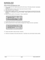
Type M3 Assembly to Chaincase
1.
Clip moveable brake pad into position under holder clip. Hold moveable and stationary pads in place with a
rubber band while placing assembly over rotor disc and mounting to chaincase. Remove rubber bands once
system is bolted into place.
2.
Install alignment spacers (Item 9), washers (Items 3 and 4) and bolts (Item 5).
specification.
Torque assembly to
Caliper Mounting Bolt Torque 25~30
3.
ft.Jbs. (3.45-4.14 kg-m) . .
Loosen cable sleeve jam nuts (Item 1) and adjust brake cable sleeve to its shortest position.
10/98
8.36
Polaris Industries Inc.
BRAKES/FINAL DRIVE
Type M3 Mechanical Brake System
Type M3 Brake Adjustment
A
WARNING
The following step is critical for proper positioning of the actuating arm to the caliper helix shaft. Improper
positioning will result in minimal resistance and ineffective brakes.
4.
With brake lever bottomed on handlebar (as if brakes were applied) and helix shaft (D) bottomed in caliper,
install actuating arm, jam nut locking tab, jam nut and adjuster bolt. Release brake arm slightly to index lever
for installation on helix shaft.
5.
Insert a .015" (.04 em) feeler gauge between brake disc and moveable brake pad. Release brake lever. Install
return spring (Item 13) and finger tighten bolt (Item 24). Set adjuster bolt jam nut, bend locking tab and remove
feeler gauge.
Friction Pad Air Gap .015" (.38 mm}
6.
Field test machine for proper braking action before putting into service. If braking action is soft, re-index helix
shaft and repeat steps 3. - 6.
Polaris Industries Inc.
8.37
10/98
BRAKES/FINAL DRIVE
Type WT Mechanical Brake System
The Type WT system is the mechanical brake system used only on Indy WideTrak models.
1.
2.
3.
4.
5.
6.
7.
8.
9.
1 0.
11.
12.
13.
14.
15.
16.
17.
18.
19.
21.
20.
21.
Brake Cable and Jam Nuts
Bracket, Brake Cable
Washer
Washer, Spring Lock
Bolt, Top Mount
Bracket, Brake Top Mounting
Bushing
Nut, Bi-Lock
Adjuster Bolt
Caliper, Stationary, Cast
Pad, Brake
Puck, Moveable Brake
Spring, Brake Return
Nut
Bushing, Brake Arm
Bolt, Cable Swivel
Clevis, LT
Bolt, Caliper
Brake Disc
Seal
Caliper (Moveable Puck)
Transmission
5----f
4----4
2
l
3----
10
11
12
20
Type WT Brake Disassembly
Whenever inspection reveals worn, damaged or defective parts, replacement is necessary in order to avoid
serious damage to the machine or injury to the operator.
1.
Open adjuster bolt jam nut locking tab (A). Loosen jam nut and remove adjuster bolt (B).
2.
Remove actuating lever (C) and return spring. Do not disconnect lever arm from cable.
3.
Remove caliper bolts, spacers, bracket nuts {Items 1, 2, 7, & 8). Remove stationary caliper casting and
stationary pad (Items 10 & 11).
4.
Remove top mounting bolts and washers {Items 3, 4, & 5). Pull outward on disc with the balance of the caliper
assembly. Once disc is free of shaft separate components.
5.
Remove brake pads and inspect for wear and damage. Replace if necessary. If stationary pad {Item 11) is
stuck to stationary casting, tap on the side of the pad with a punch and hammer to break it loose.
6.
Inspect rotor disc and replace if necessary.
10/98
8.38
Polaris Industries Inc.
BRAKES/FINAL DRIVE
Type WT Mechanical Brake System
Type WT Assembly and Installation to
Transmission
1.
Clip moveable brake pad into position under
holder clip. Hold moveable and stationary
pads in place with a rubber band while placing
assembly over rotor disc and mounting to
transmission. Remove rubber bands once
system is bolted into place.
2.
Apply a light coating of RTV silicone to
transmission shaft. Position moveable caliper
pad assembly along with mounting bracket
(Item 6) and brake disc onto transmission as a
unit. Slide disc fully over shaft.
3.
Assemble bolts, spring washer, and flat
washers to transmission and top mounting
bracket (Items 3, 4, 5, & 6). Finger tighten.
4.
Assemble bolts, spacers, and cable bracket to
top mounting bracket and moveable caliper
pad assembly (Items 18, 7, 2, 6, & 20).
Position stationary caliper pad assembly
inside top mounting bracket pushing bolts
through stationary assembly. Install spacers
and lock nuts on bolts and torque to
specification.
Caliper Bolt Torque
8 ft.lbs~ (1.10 kg-m)
,,
,',.j_!,
Type WT Adjustment
1.
A
Loosen cable sleeve jam nuts (Item 1) and adjust brake cable sleeve to its shortest position.
WARNING
The following step is critical for proper positioning of the actuating arm to the caliper helix shaft. Improper
positioning will result in minimal resistance and ineffective brakes.
2.
With brake lever bottomed on handlebar (as if brakes were applied) and helix shaft (D) bottomed in caliper,
install actuating arm, jam nut locking tab, jam nut and adjuster bolt. Release brake arm slightly to index lever
for installation on helix shaft.
3.
Insert a .015" (.04 em) feeler gauge between brake disc and moveable brake pad. Release brake lever. Install
return spring (Item 13) and finger tighten bolt (Item 9). Set adjuster bolt jam nut, bend locking tab and remove
feeler gauge.
Friction Pad Air Gap .015" (.38 mm).
4.
Field test machine for proper braking action before putting into service. If braking action is soft, re-index helix
shaft and repeat steps 1. - 4.
Polaris Industries Inc.
8.39
10/98
BRAKES/FINAL DRIVE
Type 3 Drive System
Type 3 Drive System Disassembly (Except WideTrak)
The Type 3 drive system is used on all models except the WideTrak. This system consists of a right side mounted
chaincase with right side mounted brake assembly.
Rear Suspension Removal
1.
Mark hood hinges for ease of alignment when
reassembling.
Remove hood (to prevent
damage), air silencer, exhaust system and
battery, if so equipped. Place drip pan under
chaincase and remove drain plug. Dispose of
used chaincase oil properly.
2.
Turn fuel valve off.
3.
Remove drive belt and driven clutch. Note
position of washers for controlling drive to driven
offset (A) and washers to control clutch free
floating (B).
4.
Loosen jackshaft bearing lock set screws (if
equipped).
NOTE: Some models are equipped with set screw or
Skwez-loc"' style jackshaft bearings. Some models
are equipped with press-fit bearings which have no
locking device.
Press On Bearing
Set Screw Bearing
Skwez-loc™ Bearing
5.
Remove two upper flangette attaching bolts.
10/98
8.40
Polaris Industries Inc.
BRAKES/FINAL DRIVE
Type 3 Drive System
Rear Suspension Removal, Cont.
6.
Remove three bolts, nuts, and washers securing angle
drive and bearing flangettes. Remove and discard
adaptor key.
7.
Remove four suspension mounting bolts.
8.
Place a protective mat on floor and tip machine onto
left side.
9.
Remove rear suspension by pulling rear of track
outward and sliding suspension forward. Lift out rear
of suspension first.
NOTE: Unhook the rear torsion springs to relieve pressure
on the torque arm for ease of removal. Loosen rear shaft
bolts and adjuster bolts, slide rear shaft forward for ease
of removal.
Chaincase Removal
1. Remove third jackshaft flangette attaching bolt.
Tip machine back to upright and support rear with jackstand.
2.
Remove chaincase cover attaching bolts and remove
cover.
3.
Remove cotter pin and nut.
4.
Loosen chain adjustment bolt and remove chain
tensioner assembly.
5.
Remove bottom sprocket attaching bolt, chain and
sprockets.
6.
Remove two bolts securing caliper carrier bracket to
chaincase.
NOTE: Inspect brake pad condition and replace if worn to
less than 1/2 the original thickness. See Brake Pad Replacement in this chapter.
7.
Remove three chaincase to bulkhead attaching nuts
and bolts. The front bolt is a through bolt, rear and
bottom bolts are carriage bolts.
NOTE: On some machines it may be necessary to remove
the rear exhaust bracket prior to lifting chaincase or removing drive shaft assembly.
Polaris Industries Inc.
8.41
10/98
BRAKES/FINAL DRIVE
Type 3 Drive System
Chaincase Removal, Cont.
8.
Tap on end of driveshaft with a soft face hammer and
slide the chaincase off of the driveshaft. Remove
chaincase.
Chaincase Bearing Removal
1.
Remove bearing retaining snap rings.
2.
Pry out old seal from back side of chaincase.
3.
Press out old bearing from side shown. If bearing
appears tight, use heat to expand chaincase
bore. Always press bearing toward snap ring
side of chaincase when removing. Inspect
chaincase for any damage and replace if
required.
Jackshaft Removal
1.
Remove 0-Ring, seal sleeve and brake disc by tapping
on jackshaft end with a soft face hammer as shown.
2.
Remove jackshaft.
3.
For set screw and Skwez-loc bearings, inspect drive
shaft and jackshaft in bearing contact area. If
diameter is .001" (.025 mm) less than non-contact
area, shafts should be replaced.
··Jackshaft and DriveshaftService Limit'/)!='',<;~·
'
NOTE: On models with pressed bearing on jackshaft, shaft
will have to be brought through bulkhead slot in order to remove from unit.
10/98
8.42
Polaris Industries Inc.
BRAKES/FINAL DRIVE
Type 3 Drive System
Driveshaft Removal
1.
Tip machine back on left side.
2.
Remove driveshaft by pushing through bearing hole on
the bulkhead, then pulling driveshaft toward you.
3.
After drive shaft has been removed, inspect
condition of drive sprockets and replace if required.
NOTE: On models with pressed bearings on drive shaft:
If bearings are loose internally or rough they should
be replaced.
•
If bearings are loose on the shaft the shaft must be
replaced.
Polaris Industries Inc.
8.43
10/98
BRAKES/FINAL DRIVE
Type 3 Drive System
Chaincase Assembly
1.
Apply Loctite 680 to outer race of new bearing and
press into position. Press on outer race only, or
bearing damage may result.
Loctite™ 680
PN 2870584
2.
Reinstall snap rings.
3.
Press new seals in until outer edge is flush with
chaincase shoulder. New seals must be installed
from outside of case with lip side in.
4.
Install chaincase.
NOTE: Do not tighten chaincase bolts at this time.
Jackshaft Installation
1.
Replace seal sleeves and 0-Rings with new and
grease.
2.
Install jackshaft installation tool on the threads of
the jackshaft
'
'
'
Jackshaft Installation Tool .
PN 2870974-13 Tooth Jackshafts
PN 2871296 -15Tooth Jackshafts
3.
Insert jackshaft through bearing in chaincase
4.
Install jackshaft alignment tool and secure with
castle nut and flat washer. Tighten jackshaft nut
securely to ensure positive bearing and jackshaft
seating to chaincase.
NOTE: Use of a standard nut and flat washer for this alignment process will simplify the process as well as preserve
the locking features of the lock nut for reassembly.
Jackshaft Alignment Tool
·.<
PN 2870399- 13 Tooth Jackshafts
PN 2871535 - 15 Tooth Jackshafts
10/98
8.44
Polaris Industries Inc.
BRAKES/FINAL DRIVE
Type 3 Drive System
Jackshaft Installation, Cont.
5.
If shaft is not centered, tap shaft with a soft faced
hammer until centered. This will align the upper
chaincase bearing in the chaincase bore.
6.
Once correct jackshaft alignment has been achieved,
install lock nuts on chaincase mounting bolts and
torque to specification. Remove alignment tool from
chaincase.
7.
Install jackshaft flangette gasket and bolts. Align
grease hole (A) in bearing with hole or fitting in
flangette (B) to within .1 00" to ensure greasability.
Torque nuts to specification. Do not lock set screws on
retainer ring (if so equipped).
Chaincase Mounting Bolt Torque -
Flangette Nut Torque -
28-30 ft. lbs. (3.86- 4.14 kg-m)
15 - 17 ft. lbs. (2.07 - 2.35 kg-m)
Driveshaft Installation
1.
Tip machine back on its left side. Set track into
machine making note of correct direction of travel.
Most tracks have an arrow pointing which direction the
track turns.
Polaris Industries Inc.
8.45
10/98
BRAKES/FINAL DRIVE
Type 3 Drive System
Driveshaft Installation, Cont.
2.
Insert driveshaft through bearing hole in
bulkhead. Place inner driveshaft bearing flange
bolts in the bulkhead.
3.
Insert chaincase side of driveshaft through
bottom chaincase bearing.
4.
Tip machine upright. Replace speedometer key
with a new one and install angle drive. Torque
nuts to specification.
Speedometer Angle Drive
Mounting Nut Torque 15 -17ft. lbs. (2.07- 2.35 kg-Ill)
5.
Link together the upper and lower chaincase
sprockets with the chain. Install both the upper
and lower sprockets and chain at the same time.
Finger tighten the top sprocket nut and turn in
bottom sprocket bolt until snug.
NOTE: On Hyvo '" sprockets, the beveled side goes
toward the chaincase bearing.
6.
Install chain tensioner. Finger tighten adjustment
bolt.
7.
Install brake caliper assembly in chaincase.
On models with hydraulic brakes, make sure caliper
piston is fully retracted into caliper to prevent brake
binding from preload of pads. On models equipped
with mechanical brakes make sure cam is fully retracted.
8.
Torque caliper mounting bolts to specification.
Caliper Mounting Bolt Torque 28-30 ft. lbs. (3.86- 4.14 kg-m}
10/98
8.46
Polaris Industries Inc.
BRAKES/FINAL DRIVE
Type 3 Drive System
Track Installation
1.
Tip machine back onto left side. Insert suspension,
rear first, into the track.
2.
Move the suspension back and forth until front
torque arm mounting bolts can be started. Tighten
finger tight.
3.
Rotate the suspension until the rear mount bolts can
be installed in the same manner as the front.
NOTE: For ease of installation, turn the front rear scissor stops (FRSS) to low position. This allows the rear
torque arm to move forward more to line up holes.
4.
Torque suspension mounting bolts to specification.
5.
Return front rear scissor stops (FRSS) to original
position.
6.
Install suspension springs.
FRSS (Front Rear Scissor Stop)
XTRA-10 Shown
7.
Align track (outlined in suspension section) and
tighten adjuster and rear shaft bolts to specification.
3/8" Suspension Bolt Torque - :
35-40 ft. lbs (4.83-5.52 kg-m)
.<
'··..
..'
••• •
'
7/16"Suspension Bolt Torque45-50 ft. lbs. (6.21-6.9 kg-m)
Polaris Industries Inc.
8.47
10/98
BRAKES/FINAL DRIVE
Type 3 Drive System
Final Assembly
1.
Check speedometer cable routing.
Polaris Cable Lube
PN 2870510
2.
Grease angle drive and bearing with Polaris grease.
Polaris Premium All Season Grease
PN 2871423
3.
Torque bottom chaincase sprocket bolt to
specification.
Bottom Chaincase Sprocket Bolt
Torque19ft. lbs. (2.62 kg-m)
4.
Torque jackshaft nut to specification. On models
with castle nut, if cotter pin does not align, tighten
nut until it does. Apply brake to hold jackshaft
while torquing.
Jackshaft Castle Nut Torque 50 ft. lbs. (6.9 kg-m)
5.
To obtain correct chain tension, place a slight
reverse tension on the chain as indicated in the
illustration at right (A).
6.
There should be approximately 1/4-3/8" (.6-.95
em) total deflection on the chain at point (B).
Loosen adjuster bolt locknut and turn adjuster
bolt (C) until correct chain deflection is obtained.
Chain Deflection 1/4-3/8" (.6- .95 em)
10/98
8.48
Polaris Industries Inc.
BRAKES/FINAL DRIVE
Type 3 Drive System
Final Assembly, Cont.
7.
Tighten adjuster bolt locknut (A) securely while
holding the adjuster bolt (8).
8
8.
Install chaincase cover gasket in chaincase with
gap at the top. Install chaincase cover and torque
cover bolts to specification.
Chaincas'e
t~~er Bolt Torque -
8 -1oft. lbs. (1.1 o~ 1.38 kg-m}
9.
Add 9 oz. (11 oz. on models equipped with
reverse) of Polaris chaincase oil to the
chaincase. Verify proper level with dipstick.
.Polaris Synth~tic Gearcase Lube
· ·.
PN2871477 (Gallon}
Pr-J 2871478 (12 oln1ces}
10. Torque jacks haft bearing set
specification (if so equipped).
.
screws
"
to
.
•\ ',~;):i~t:;~
<
:::
f
Driveshaft anq Jackshaft Bearing
Set Screw;Torque·
·
80 in. lbs. (.92 kg-m)
~,:',, ~' \->j~i>',,
11. Lubricate bearings with Polaris Premium All
Season grease.
PN 2871423
Polaris Industries Inc.
8.49
10/98
BRAKES/FINAL DRIVE
Type 3 Drive System
Final Assembly, Cont.
12. Reinstall clutch offset washers on jackshaft and
install driven clutch. Using the clutch alignment
tool adjust driven clutch to achieve proper offset.
. Clutch Alignment Tool
P90 - PN 2870914
P85 • PN 2870426
P90 Offset 21/32": P90 Electric Start Offset: 1.28" (straight edge}
P85 Offset 5/8": P85 Electric Start Off-set:
1" (straight edge}
13. With proper offset achieved, the driven clutch must
float on the jackshaft. This is done by adding or
subtracting spacer washers (PN 7555734) to the
clutch retaining bolt. When properly adjusted, the
driven clutch will have .020 - .1 00" (.5 - 2.5 mm)
float.
[: CAUTt()N:
<I
Incorrect float can cause jackshaft bearings to be side
loaded, resulting in premature bearing failure.
14. Torque driven clutch retaining bolt to specification.
Driven Clutch Retaining Bolt Torque 12 ft.lbs. (1.66 kg-m)
10/98
8.50
Polaris Industries Inc.
BRAKES/FINAL DRIVE
Type 3 Drive System
Final Assembly, Cont.
15. Reinstall air box, adjusting box properly.
16. Reinstall battery (if so equipped). Always attach
ground cable last to prevent sparks.
17. Replace exhaust system.
18. Install hood, (if removed) aligning with marks made
during disassembly. Ensure proper hood closure
and readjust if necessary.
Hood Bolt Torque ;..
8-10 ft.lbs. (1.10-1.38 kg-m)
19. Test ride the unit to ensure all components are
functioning properly before putting into service.
Polaris Industries Inc.
8.51
10/98
BRAKES/FINAL DRIVE
Transmission, Suspension and Track Removal - WideTrak LX
1.
Hood can be removed to prevent damage. Mark
hood hinges for ease of alignment when
reassembling unit.
2.
Remove battery.
3.
Turn off fuel valve. Move oil tank for access.
4.
Remove air intake and coolant recovery bottle from
its mounting.(do not remove entirely).
5.
Remove drive belt.
6.
Remove driven clutch retaining bolt assembly and
drive clutch. Note number of spacers which are
behind driven clutch for installation during
reassembly procedures.
7.
Remove muffler springs and muffler from unit.
8.
Loosen brake cable jam nut (A) and remove cable
bolt, nut and spacer (B). Use care not to loose
spacer.
9.
Remove cable from transmission.
10. Note location of shift linkage on transmission (A) to
assure proper location during reassembly. Remove
cotter pin, washers, and pin from transmission arm.
11. Remove brake light wire connector from sensor.
10/98
8.52
Polaris Industries Inc.
BRAKES/FINAL DRIVE
Transmission, Suspension and Track Removal - WideTrak LX
12. Loosen rear idler wheels and bolts.
13. Loosen jam nuts on adjustment bolts on both sides.
Back out adjustment bolts to allow rear idler
assembly to come forward, relieving track tension.
14. Tighten idler wheel bolts so that spacers on shafts
do not rotate and lose alignment.
8
A
15. Remove front and rear carrier shaft bolts (A), and
front and rear suspension bolts from both sides (B).
16. Place a protective mat on the floor. Tip unit onto right
side and remove suspension.
17. Using "T" handle Allen wrench, loosen set screws on
lock collar.
18. Remove (2) bolts, nuts, and flangettes supporting
jackshaft bearing. Loosen and slide back lock ring
from transmission end of jackshaft.
19. Remove jackshaft by pulling towards driven clutch
side and lifting upward through bulkhead. It may be
necessary to lightly tap on bearing collar to free
coupler of jackshaft from transmission end.
20. Inspect bearing. If loose on the shaft the shaft must
be replaced. If bearing is rough when turned, the
bearing must be replaced. The bearing is pressed
onto the shaft and will require a puller for removal.
Polaris Industries Inc.
8.53
10/98
BRAKES/FINAL DRIVE
Transmission, Suspension and Track Removal - WideTrak LX
21. Loosen and remove three carriage bolts and nuts
retaining angle drive housing and flangettes.
22. Remove angle drive housing, adaptor key,
flangettes, gasket, and bearing from drive shaft and
tunnel.
NOTE: It is not necessary to remove speedometer cable
from angle drive. Replace adaptor key any time drive
train assembly is serviced.
23. Tip machine back onto floor.
24. Remove right side bumper plug (A).
25. Remove bolt retaining rear of bumper to foot rest.
26. Bend muffler mount out of the way to allow
transmission removal.
27. Remove three transmission retaining bolts. Note all
alignment shim quantities and locations for
reassembly.
NOTE: Retaining bolts have to be held in place from underside while removing nuts. The lower front bolt cannot
be removed at this time. It must be lowered to the drive
sprocket.
28. Lift and maneuver transmission to free drive shaft
coupler.
29. Lower drive shaft and remove lower front bolt.
30. Maneuver transmission until it can be removed from
the unit. Use care not to damage coolant lines.
Refer to page 8.61 for transmission disassembly.
31. With transmission removed, tip unit onto right side.
Notice direction of track rotation for reassembly. The
arrow in the photo at right indicates track bottom,
rear of unit.
32. Remove front and rear carrier shafts ..
33. Remove suspension by pulling rear of track out of
tunnel. Slide suspension forward to driveshaft. Lift
up and out at the rear.
NOTE: On some models it may be necessary to unhook
rear torque arm springs to allow torque arm to lower.
34. Inspect transmission, brakes, suspension and track
for excessive wear. Check bearings for excessive
movement or rough feeling. Replace if necessary.
10/98
8.54
Polaris Industries Inc.
BRAKES/FINAL DRIVE
Transmission, Suspension and Track Installation - WideTrak LX
Installation
1.
Tip unit onto right side.
2.
Insert track in unit, making sure direction of rotation
is correct.
3.
Place drive shaft in unit, aligning drive sprockets and
track drive lugs.
4.
Install lock collar, flangette, bearing, gasket, and
flangette on drive shaft, positioning bearing flush
with end of drive shaft.
5.
Lightly tighten set screws to hold bearing in place.
6.
Align flangette holes with tunnel.
7.
Replace adaptor key in drive shaft. Install angle
drive housing aligning adaptor key with angle drive.
8.
Install nuts and finger tighten.
9.
Tip machine onto its left side.
10. Replace 0-rings on input and output shafts. Apply
Polaris All Season Grease to drive shaft coupler
splines.
Polaris All Season Grease
PN 2871423
11. Reinstall transmission, using care not to damage
coolant hoses. Be sure transmission shift linkage is
properly located.
12. Install lower front mounting bolt (3) before coupling to
shaft. Once bolt is started into transmission housing,
align coupling with drive shaft and jack shaft splines.
Keep transmission flat and lower gradually to prevent
binding of couplers.
13. Install remaining transmission mounting bolts.
Reinstall shim washers in original positions and
tighten bolts securely.
NOTE: Proper transmission/jackshaft alignment is critical
for bearing service life. Use a standard nut and flat washer
for initial installation of transmission, and install new
mounting hardware after jackshaft alignment is complete.
14. Tip machine onto its right side.
Polaris Industries Inc.
8.55
10/98
BRAKES/FINAL DRIVE
Transmission, Suspension and Track Assembly - WideTrak LX
Assembly, Cont.
15. Loosen set screws and seat drive shaft in
transmission coupler stub shaft.
For ease of
assembly, make sure track has no pressure against
drive shaft.
16. Tighten nuts retaining angle drive housing to tunnel.
Torque to specification.
Angle Drive Housing
Retaining Nu~ Torque 15-17 ft. lbs. (2.07- 2.35 kg-m)
17. Using "T" handle Allen wrench, torque set screws to
specification.
Set Screw Torque
80 in. lbs. (.92 kg-m)
18. Reinstall suspension inside track and align with tunnel
mounting holes.
19. Install and hand tighten suspension bolts (B).
20. Install front carrier shaft assembly inside track and
mount to tunnel with bolts. Hand tighten bolts.
21. Install rear carrier shaft assembly. Make sure bolts
are not cross threaded and hand tighten (A).
22. Tip machine back onto floor and tighten all suspension
bolts to specification.
Suspension Bolt Torque 35-40 ft. lbs (4.83-5.52 kg~m) ·
10/98
8.56
Polaris Industries Inc.
BRAKES/FINAL DRIVE
Transmission, Suspension and Track Assembly- WideTrak LX
Assembly, Cont.
23. If jackshaft was removed from unit, grease coupler
spline with Polaris Premium All Season Grease and
install on transmission.
Polaris Premium All Season Grease
PN 2871423
24. Check for bearing to bulkhead alignment and shim
transmission as required to center jackshaft in
bulkhead mount. Shims may be required between
transmission and bulkhead. Seat jackshaft firmly.
Shim Kit PN 2200126
25. Once properly aligned, install flangettes. Align grease
holes in bearing and flangette.
26. Replace nuts holding transmission in place with
proper lock nuts and torque to specification.
Transmission Retaining Nut Torque 28-30 ft.lbs. (3.86-4.14 kg-m)
27. Install bolts and nuts securing flangettes to bulkhead.
Torque to specification.
Bearing.Fiangette Nut Torque15-17 ft. lbs. (2.07-2.35 kg-m)
28. Set lock ring at transmission coupler and torque to
specification.
......
~
t
Lock Ring Torque -
0
A
80 in. lbs. (.92 kg-m)
Polaris Industries Inc.
_
8.57
10/98
BRAKES/FINAL DRIVE
Transmission, Suspension and Track Assembly - WideTrak LX
Assembly, Cont.
29. Reattach transmission shift linkage and brake light
connector. Check transmission fluid level and fill if
necessary.
Polaris Synthetic Gearcase Lube
PN 2871477 Gallon
PN 2871478 12 oz.
30. Attach brake cable to transmission mounting with
bolt, nut and spacer.
31. Install bumper onto footrest bolt and tighten.
32. Reinstall bumper plug.
33. Reinstall and secure muffler.
34. Install battery, air box, oil tank, and coolant recovery
bottle.
35. Loosen rear idler bolts.
36. Reinstall driven clutch and spacers onto jackshaft and
tighten.
37. Reinstall clutch offset washers on jackshaft and
install driven clutch. Using the clutch alignment
tool adjust driven clutch to achieve proper offset.
P85 Electric Start Offset: 1" with
straight edge
38. WideTrak models have no float on driven
clutches. Use shim washers (PN 7555734) to
create gap between shaft and cover washer only.
10/98
8.58
Polaris Industries Inc.
BRAKES/FINAL DRIVE
Transmission, Suspension and Track Assembly - WideTrak Models
39. Torque driven clutch retaining bolt to specification.
Driven Clutch Retaining Bolt Torque .;;
12 ft.lbs. (1.66 kg-m)
40. Lift and support rear of unit and align track to
specifications found in the Maintenance section.
Make sure rear idler wheel spacer location is correct
before tightening idler wheels.
41. Reinstall hood.
Polaris Industries Inc.
8.59
10/98
BRAKES/FINAL DRIVE
Transmission Disassembly WideTrak LX
Disassembly/Inspection
1.
Drain transmission oil into suitable container.
2.
Remove snap ring, spacer washer, and brake
disc.
NOTE: Note position of spacer washers behind disc
for proper alignment upon reassembly.
3.
Remove detent spring and ball.
4.
Remove case bolts evenly in a criss-cross
pattern.
10/98
8.60
Polaris Industries Inc.
BRAKES/FINAL DRIVE
Transmission Disassembly WideTrak LX
5.
Tap cases apart with soft faced hammer in the
reinforced areas indicated in photo at right. Tap
end of brake shaft to be sure it remains in case.
6.
Hold chain tensioner ratchet pawl off ratchet
teeth and push tensioner plunger all the way in.
Insert a 1/8" diameter rod as shown to hold
tensioner in released position.
Remove
tensioner assembly. Inspect for cracks, chipped,
broken, or rounded teeth.
7.
Remove shift arm
8.
Remove shaft and gear assembly from case by
tapping with a soft faced hammer evenly on end
of shafts.
9.
Remove output gear assembly and chain. Mark
chain direction for reference during reassembly.
Inspect gear teeth for damage. Inspect chain for
worn, cracked, or broken link plates.
Polaris Industries Inc.
8.61
10/98
BRAKES/FINAL DRIVE
Transmission Disassembly WideTrak LX
10. Remove shift fork shaft from gear cluster. Inspect
surface of fork for wear or bending.
11. Remove chain from input and reverse shaft.
Inspect gear teeth for damage. Inspect chain for
worn, cracked, or broken link plates.
12. Inspect dog gears and slots in mating gears
closely. Rounded edges will cause gears to
disengage under load. Replace both dog gear
and mating gear if edge of dog and/or slot is
rounded. Inspect gears for chipped, cracked, or
broken teeth.
10/98
8.62
Polaris Industries Inc.
BRAKES/FINAL DRIVE
Transmission Disassembly WideTrak LX
Gear, shaft, and chain cluster assembly shown.
Low gear output power flow ...
High gear output power flow ...
Reverse output power flow...
Polaris Industries Inc.
8.63
10/98
BRAKES/FINAL DRIVE
Transmission Disassembly WideTrak LX
Low I Reverse Shaft Disassembly
13. Press bearing from end of shaft using a bearing
separator.
14. Remove snap ring and spacer washer.
10/98
8.64
Polaris Industries Inc.
BRAKES/FINAL DRIVE
Transmission Disassembly WideTrak LX
15. Remove low reverse shaft low gear...
needle bearing, thrust washer, low/reverse dog
gear...
snap ring, thrust washer (.050"), reverse idler, needle
bearing, and thrust washer (.065").
16. Closely inspect drive dogs. Replace gear and
mating gear if rounded, chipped or broken.
17. Inspect needle bearings for wear or cracks on cage.
Shiny spots on cage indicate wear and the bearing
should be replaced. Inspect shaft and thrust washers
for galling or wear. Always replace snap rings if
removed.
Polaris Industries Inc.
8.65
10/98
BRAKES/FINAL DRIVE
Transmission Disassembly, WideTrak
Shift Fork Disassembly
1.
Remove the detent cam, spring and shaft.
2.
Check condition of key way and key. Inspect indicator, spring legs and detent areas for wear. Replace parts
as required. NOTE: The spring must be pre-loaded upon installation. Refer to photo and illustration below.
Locate spring in retainer
slot as shown
Hook spring here
Arm of detent plate must
be positioned between
ends of spring. Install key.
Transmission Assembly
Lubricate all parts before assembly with Premium Synthetic Chaincase Lubricant.
1. Install chain on input and reverse shaft. Photo 1.
2. Add output gear assembly with chain. Photo 2.
Photo 2
Photo 1
3.
4.
5.
6.
7.
8.
Add shift fork assembly.
Install entire assembly in case half.
Lock tensioner plunger in retracted position before
installation by installing a 1/8" dowel as shown in photo
at right (where applicable). If washers were removed
upon disassembly, re-install them between tensioner
and case. Torque bolts to 10 ft.lbs. (1.38 kg-m).
Apply 3 Bond™ 1215 Sealant to case halves.
Install outer case half and replace brake cable bracket.
Torque bolts in three steps to 8-10ft. lbs. (1.10-1.38
kg-m) using a criss-cross pattern. Remove dowel from
tensioner and install access plug (where applicable).
Install transmission. Add 20 oz. Premium Synthetic
Chaincase Lubricant.
Transmission Case
Bolt Torque-.
.
.
..
I
8-10ft. lbs. (1.1o-1.38 kg-m).
10/98
8.66
Polaris Industries Inc.
BRAKES/FINAL DRIVE
Brake Caliper Removal WideTrak LX
8.
Install seals, shift arm, brake disc and caliper. Install
detent ball, spring, and spring guide. Fill with 20
ounces
(600cc)
Polaris
Premium
Synthetic
Transmission Oil.
Synthetic Chaincase lubricant:..
Gallon PN2871477
12 oz. PN 2871478
Brake Caliper Removal -Type WT2
1.
2.
Remove brake cable.
Remove retaining bolts, making note of location of hex
head bolt (with flat washer) and recessed Allen bolt.
NOTE: Before performing next step, note position of two
spring clips.
3.
Remove upper guide bushing and pads. Remove
lower guide bushing. Inspect pads and replace if worn
beyond service limit.
Minimum Pad
Thickness
.250"
(6.35mm)
Brake Pad Thickness -Type WT2
. Service limit
4.
5.
6.
.250" (6.35mm)
With actuating arm facing up, carefully remove tension
from the return spring.
Remove the arm using care not to lose the balls, ball
spacer, or lifter ramp.
Inspect balls, ball spacer, lifter ramp and caliper
housing for galling or wear. Replace if necessary.
Polaris Industries Inc.
8.67
10/98
BRAKES/FINAL DRIVE
Brake Caliper Assembly WideTrak LX
Assembly
1.
Apply a light film of grease to balls and ball spacer.
Install in caliper housing.
2.
Install lifter ramp. NOTE: Ramp may be installed in
any position.
3.
Install spring and arm with arm located in 8:00 position
as shown in photo at right.
Install lower guide bushing and both spring clips. Place
pads against lower bushing spring clip and tip into
position.
Install upper guide bushing.
4.
5.
Installation
6.
7.
Install hex head bolt with washer in top guide
bushing. Install Allen head bolt in recessed bushing
as shown.
Reinstall brake actuating cable and adjust as
outlined on page 2.25a of the Maintenance Section.
Tighten cable lock nuts securely.
Lock
Nuts
Move cable up or
down in bracket
to adjust freeplay
10/98
8.68
Polaris Industries Inc.
BRAKES/FINAL DRIVE
Reverse Kit Service Tips
The following illustration indicates sprocket position with the Polaris Reverse Kit in the forward and reverse selection.
Installation Tips (Refer to Illustration on page 8.70)
• When installing pinion shaft, be sure the chamfered end of pinion shaft is toward case cover.
• Install chain, top sprocket, bottom option sprocket and wide face pinion gear into case at the
same time.
• When installing case cover, be sure that shift fork has slipped into fork groove of reverse gear.
-I
Reverse Position
Forward Position
Top Sprocket - ; -
~--
Drive Chain
/Top Sprocket
-~
Chain Pinion Gear
(Narrow Face)
Spur Pinion Gear
.........._ Spur Pinion Gear
Shift Fork Groove
Reverse Kit Option Sprocket
Reverse Kit Option Sprocket
Drive Coupler
Polaris Industries Inc.
8.69
10/98
BRAKES/FINAL DRIVE
Reverse Kit Maintenance
Washer
Washer
Washer
Pinion Shaft
Pinion
Gear Drive
Washer
Drive Coupler
Reverse Gear
Chain Tension Adjustment
1.
Elevate the rear of machine and support so track is
off the floor.
2.
Loosen adjuster bolt lock nut.
3.
Loosen adjuster bolt slightly (about one turn out).
4.
Tighten adjuster to specified torque.
',,
Adjust~r Bolf;Torque ,> '·\'-
,:',\\'"·~\
{«;,,j
20, in.'i~s. (:23 kg-m)
5.
Loosen adjuster bolt 1/2 turn.
6.
Hold adjuster bolt in position and tighten locknut
securely.
10/98
8.70
Polaris Industries Inc.
BRAKES/FINAL DRIVE
Reverse Kit Maintenance
Oil Level
1.
2.
3.
Using Polaris chaincase lubricant, maintain proper
oil level. Proper level is checked by removing
dipstick.
Wipe off any metal particles from the dipstick.
Small amounts of particles will be common.
Add lubricant until the level is in the "safe" zone on
the dipstick (11 oz.) Do not mix or use other types of
lubricant.
Polaris Synthetic Chaincase Lube
PN 2871477- Gallon
PN 2871478 -120unces
Adjustment
Due to break-in or replacement of components, the reverse shift mechanism may require adjustment. Adjust
with the shifter in the forward position.
Indy 340 Style
1.
Loosen jam nuts on lower end of cable.
2.
Adjust cable until endplay movement of cable
housing at the handlebar bracket is 1/32" (.08 em).
Do not adjust beyond this point.
3.
Tighten jam nuts and re-check adjustment.
1/32" Adjustment
(.08 em)
Reverse Cab,le End Play - ··
1/32" (.08 em)
.,·,
Evolved and Aggressive Style
1.
Lift shift lever slowly while observing shift arm on
transmission.
2.
If adjustment is correct, shift will move 1 - 1 1/2"
before the shift arm begins to move. If adjustment is
required, proceed with step 3.
3.
Loosen jam nuts on lower end of cable.
4.
Adjust cable end at transmission until the end of the
shift lever has 1 - 1 1/2" (2.5 - 3.8 em) of freeplay
before the cable starts to move the shift arm. Do not
adjust beyond this point.
5.
Tighten jam nuts and re-check adjustment.
Shift Lever
1-1 1/2" (2.5-3.8 em)
free play
Shift
Arm
Reverse Shift Lever Freeplay 1 - 11/2" (2.5.- 3.8 em)
Polaris Industries Inc.
8.71
10/98
BRAKES/FINAL DRIVE
Reverse Kit Maintenance - Gen II Style
Oil Change
1.
Change annually, prior to off season storage.
Adjustment
Due to break-in or replacement of components, the reverse shift mechanism may require adjustment. Adjust
with the shifter in the forward position.
Clevis Pin
J
GenII Style
1.
Pull shift lever slowly while observing shift arm on
transmission.
2.
If adjustment is correct, the sprockets will mesh fully
when the lever is pulled and no grinding will occur
indicating incomplete engagement. If incomplete
engagement is suspected perform the following
steps.
1.
Move lever to forward position.
2.
Loosen jam nuts on linkage rod.
3.
Adjust linkage rod until endplay movement is 1/32"
(.08 em). Do not adjust beyond this point.
4.
Tighten jam nuts and re-check adjustment.
- t - - - Shift
Lever
Actuator
Reverse Linkage Rod End PlayLinkage Rod
1/32" (.08 em)
'
Chaincase Cover Assembly
10/98
8.72
Polaris Industries Inc.
BRAKES/FINAL DRIVE
Traction
The amount of traction required varies depending upon the type of riding and the snowmobile's horsepower.
A
WARNING
A proper balance of traction products on the skis and track must be maintained to obtain proper vehicle control
on hard packed snow and ice. Loss of control can result in severe personal injury or death.
Track studding will enhance braking control on hard packed snow or ice, but extreme caution is still required on
such surfaces. Use extra caution when track studding is employed as steering ability may be reduced on hard
packed snow or ice. The addition of carbide skags (if not already installed) is recommended with studded tracks
to aid in maintaining proper vehicle steering and control. Proper balance must be maintained between the number
of studs and the length and sharpness of carbide on skags.
If you are adding studs to the track of a machine it will probably be advisable to add carbide skags or change to
more aggressive skags in order to maintain proper vehicle control while turning on hard packed snow or ice. If
the machine is equipped with carbide skags or if you are adding them or changing to more aggressive skags than
standard equipment, it may also be necessary to add track studs in order to maintain proper vehicle control while
turning on hard packed snow or ice.
As a rule of thumb, the more studs, the longer and sharper the carbide on the skags should be. The recommendations in the chart on page 8.74 should be used as guidelines in achieving a proper balance of ski and track traction
products on Polaris snowmobiles.
Studs are designed specifically for each riding category. They're made in various lengths, shapes, and materials.
Improperly applied studs can cause poor traction and premature wear. Studs which are too long can cause damage to the tunnel and heat exchangers.
Stud points fall into two categories: conical and scoopers. Conical studs (or picks) penetrate into the ground for
increased traction. Scoopers use a flat surface to hold more ground for traction. Generally, a penetrating point
is used for hard ground surfaces and ice. Scoopers are used on softer surfaces.
Material contributes more to stud life and cost than to functionality. Carbide is the most durable and lasts much
longer than steel. Studs should be installed no closer than 1"from the edges of the track. Avoid the center of
the track because there is poor support in this area. The track's center belt controls acceleration. The two smaller
outside track belts contribute to acceleration, but also increase the amount of ski pressure required for turning.
The chart on page 8.74 is a guideline for the quantity of studs to install.
•
Be sure to check allowable clearance between the track and tunnel or heat exchangers, factoring
in suspension travel.
•
Do not place studs under the tunnel protector/heat exchanger strips (directly above slide rails on underside of tunnel). Tunnel protectors are vital components and must not be subjected to stud damage.
•
V-shaped stud patterns with the least repetition work best. Studs should cover as many different lines
in the ice as possible.
•
Studs closest to the slide rails provide the most effectiveness, because the weight of the sled is concentrated in this area; however do not place studs closer than 1" to the edge of the track window.
Polaris Industries Inc.
8.73
10/98
BRAKES/FINAL DRIVE
Traction
Polaris Push-Through Stud and Skag Recommendations
Model
TRACK
L&W
Indy 340
*340 Deluxe
Sport
*Super Sport
XCF
*Trail
Indy 500
*500 Classic
XLT SP
*XLT Classic
500XC
500XC SP
600XC
600XC SP
700XC
700XC SP
440XCR
700XCR
800XCR
340 Touring
Sport Touring
*Trail Touring
*Classic Touring
*XLT Touring
*700 SKS
Trail RMK
500 RMK
600 RMK
600 RMK0pt2
700 RMK
700 RMK Oj>l 2
Transport
"WideTrak LX
121 X 15
121 X 15
121 X 15
121 X 15
121 X 15
121 X 15
121 X 15
121 X 15
121 X 15
121 X 15
121 X 15
121 X 15
121 X 15
121 X 15
121 X 15
121 X 15
121 X 15
121 X 15
121 X 15
133.5 X 15
133.5 X 15
133.5 X 15
133.5 X 15
133.5 X 15
136 X 15
136 X 15
133.5 X 15
136 X 15
136 X 15
136 X 15
136 X 15
141 X 15
156 X 20
TUNNEL
LUG
HEIGHT PROTECTOR
.66
.66
.71
.82
.82
.82
.82
.82
.82
.82
.82
.82
.91
.91
.91
.91
.82
.91
.91
.82
.82
.82
.82
.82
1.25
1.25
1.25
1.75
2.0
1.75
2.0
1.125
1.0
STUD
SIZE
2871689
2871689
2871911
2871544
2871544
2871544
2871544
2871544
2871544
2871544
std(coolers)
std(coolers)
std(coolers)
std( coolers)
std( coolers)
std(coolers)
std(coolers)
std
std
2871543
2871541
2871541
2871541
2871541
0.75
0.75
0.75
1
1
1
1
1
1
1
1
1
1.075
1.075
1.075
1.075
1
1.075
1.075
1
1
1
1
1
N/A
N/A
N/A
N/A
N/A
N/A
N/A
N/A
N/A
N/A
N/A
N/A
N/A
NIA
N/A
N/A
N/A
STD
TRAIL
STUD
QTY
TRAIL
SKAG
48
B
48
c
48
48
48
48
48
48
D
96
96
96
96
96
96
96
96
96
96
96
53
53
53
53
80
N/A
N/A
N/A
N/A
N/A
N/A
NIA
N/A
N/A
c
R (COMP)
N
D
R (COMP)
R (COMP)
R (COMP)
R (COMP)
R (COMP)
R (COMP)
R (COMP)
R (COMP)
R (COMP)
R (COMP)
R (COMP)
R (COMP)
D
D
N
R(COMP)
R (COMP)
R (COMP)
R (COMP)
R (COMP)
R (COMP)
R(COMP)
R (COMP)
R (COMP)
DorM
J orP
AGGR
STUD
QTY
72
72
72
72
72
72
72
72
120
120
120
120
120
120
120
120
120
120
120
80
80
80
80
106
N/A
N/A
N/A
N/A
N/A
N/A
N/A
N/A
N/A
AGGR
SKAG
Performance
STUD
QTY
Performance
SKAG
D
96
D
N
96
D
96
96
96
96
120
120
144
144
144
144
144
144
144
144
144
144
144
106
106
106
106
132
J
p
N
R (COMP)
N
D
R (COMP)
R (COMP)
R (COMP)
R (COMP)
R (COMP)
S(COMP)
S (COMP)
S (COMP)
S (COMP)
S (COMP)
S (COMP)
S(COMP)
D
D
N
R (COMP)
R (COMP)
R (COMP)
R (COMP)
R (COMP)
R (COMP)
R(COMP)
R (COMP)
R (COMP)
N/A
N/A
N/A
N/A
N/A
N/A
NIA
N/A
N/A
N/A
N/A
J
S (COMP)
J
p
R (COMP)
S(COMP)
S(COMP)
S (COMP)
S (COMP)
S (COMP)
S (COMP)
S (COMP)
S (COMP)
S (COMP)
S (COMP)
S (COMP)
p
p
J
S (COMP)
S(COMP)
S (COMP)
S(COMP)
S (COMP)
S (COMP)
S (COMP)
S (COMP)
S (COMP)
N/A
N/A
*EZ Steer skag
10/98
8.74
Polaris Industries Inc.
BRAKES/FINAL DRIVE
Traction
Polaris Push-Through Stud and Skag Recommendations
B
7/16 x 3" 120°, 2870693
C
7/16 x 3" 120° EZ, 2870997
D
7/16 X 4" 60°, 2871288
J
7/16 x 6" 60° EZ, 2871416
N
7/16 x 4" 60° EZ, 2871603
P
1/2x6"60°,2871601
Stud Kits
See Accessory Order Forms for Stud Kits
1/2 X 8" 60°, 2871602
Polaris Composite Ski
R 7/16 X 4" 60°, 2871688
S
1/2 X 6" 60°, 2871687
Wear Strip Kits**
2871911
1 piece tunnel Sport 1.05
2871540
1 piece tunnel SKS .625
2871541
1 piece tunnel SKS .75
2871544
121" .75
2871542
2 piece tunnel SKS .625
2871543
2 piece tunnel SKS .75
2871545
121" .625
2871689
.751ndy 340
* Patent Pending Carbide 60° Point
** Production set up of wear strips will be located over the windows of the track. An optional position is available
for using hooker plates. Only the outer end holes are punched in the tunnel. The wear strip will serve as the
template for drilling the remaining holes.
Polaris Industries Inc.
8.75
10/98
BRAKES/FINAL DRIVE
Traction
Stud Installation
1.
Mark the stud pattern on the track.
2.
3.
Drill stud holes with a 1/4" (or 7mm) hollow-core drill bit. Make sure the drill is sharp for a clean hole.
Spin the non-cutting portion of the drill shank in the hole at high speed to melt the cords together, or melt them
with a 1/4-9/32" heated probe. This will prolong track life.
T-nut Studs
1.
Push a T-nut tool through the hole from the outside of the track.
2.
With the barrel end of the T-nut toward the track, spin aT-nut onto the tool. Pull the T-nut into the track until the
head is flush with the track.
3.
4.
5.
6.
Remove the tool and put a drop of Loctite™ 262 or 271 on the nut threads and stud threads.
Secure the T-nut, slide a support washer onto the stud, and screw the stud into the T-nut
Torque to 80-100 in. lbs. and let dry for 24 hours at room temperature.
Check for loose studs after each event.
Push Through Studs
1.
2.
3.
Push stud through track hole from inside track. Hand tighten domed support plate and Nyloc nut on the
exposed stud.
Tighten with a socket on the nut and a 5.32" Allen wrench on the stud head. Tighten nut until the domed
washer bottoms out on the stud shoulder. If tightened beyond this point, the threads will be stripped.
Inspect for loose nuts after each event.
Refer to the diagrams below for stud length recommendations.
Penetration
Stud Length
A= Stud Height
B =Washer Thickness
C =Track Lug Height
A + B - C = Penetration
Maximum
Penetration
Maximum
Stud Length
Standard Low Profile Track
"\J
3/8"
v "\J
.750"
Deep Lug Track
-~/l'----'---1__
.875"
Steel Cleated Track
Backer Plates
Steel .195
"'J lf "'J
3/8"
3/8"
=
I
v
I
.700"
Aluminum .220 c:,===~
Stud Mate .148
Hooker
~
Washer .025 "0dY
10/98
~
@
Alum.
Shim .055
8.76
Polaris Industries Inc.