1
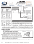
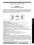
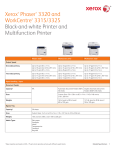
Excutive Office
255 E. Brown Street
Birmingham, MI 48009
Phone: 248-433-1824
Fax: 248-433-1824
Fax2: 248-594-3433
Machine Division
3110 Permawick Drive
Columbus, IN 47201
Phone: 812-376-0703
Fax: 812-376-8305
____________________________________________
PERMAWICK
The Industry Standard
for Fractional Horsepower
Motor Lubrication
____________________________________________
Service Manual
for the
ST 1-802
Permajector
SERVICE MANUAL - ST 1-802
SINGLE STATION PERMAJECTOR
Ver. 1.3
Table of Contents
Machine Setup and Operation
1, 2
Power Connections/Electrical Panel
3
Controls
4
Air System Connections
5
Permawick Hopper
6
Metering System
7
General/Preventive Maintenance
8
Troubleshooting Guide
9
Service Policy
10
Seal Chart
11
Standard Cycle
12, 13, 14
SERVICE MANUAL - ST 1-802
SINGLE STATION PERMAJECTOR
Machine Setup and Operation
Remove the Permajector from shipping crate and place it level on the floor. It is
not advised to use the shipping skid as a machine base.
Connect air supply to the Filter-Regulator-Lubricator (see page 5) and maintain
approximately 80 to 90 PSI. A fitting to adapt to your air system may be required.
Using at least one bucket of Permawick to start with, place the bucket upside down
on the floor for 15 to 30 minutes before putting the Permawick in the hopper. This
will provide even distribution of oil throughout the Permawick material.
Note: Never exceed a total of 2 buckets in the Hopper (see max. fill level page 6).
Connect electrical supply (see page 3). Power to supply the Permajector is usually
480 Volts (3 Phase) unless a different voltage is specified (Ex: 380V).
After power is connected, turn the machine on and open the top door to the hopper,
viewing the stirring paddle rotation direction during MORNING START cycle.
If the stirring paddle is rotating counter-clockwise, it will be necessary to switch
two of the input supply wires; reversing polarity. Be sure to turn off the main power
disconnect switch first.
To operate the machine after the MORNING START cycle is complete:
1. With no parts on the holding fixture, only a towel, cycle the machine 3 times.
Then clean nozzle with air or wipe with a clean towel. Do not use the Permawick
material that has been shot into the towel; it must be disposed of.
2. Remove towel, and place the designated endshield and associated parts on the
holding fixture; noting proper orientation (see tooling assembly drawing).
3. To operate, press both CYCLE buttons and hold momentarily, then release.
4. After the injection is complete, remove part from fixture and repeat.
Page 1
SERVICE MANUAL - ST 1-802
SINGLE STATION PERMAJECTOR
Machine Setup and Operation
If you plan to relocate the Hopper from the Permajector machine, or you have purchased
a stand alone inject station and Hopper; the following are important guidelines to follow.
1. Always try to locate the Hopper as close as possible to the Metering System, preferably
2 to 4 feet; do not exceed 10 feet. Long runs can cause pumping and injection problems.
2. Use steel hydraulic tubing 5/8 inch minimum diameter at .042 - .060 inches thick. A high
quality steel-braided hydraulic hose with Teflon lining could be used for short runs if
necessary, but is not recommended. The hose could deteriorate over time and can cause
plugging and injection problems.
3. Minimize the number unions used, and number of bends in the tubing. Avoid sharp
corners when forming the tubing, a 3 to 6 inch radii is recommended.
4. Avoid using reducers and adapters when possible. Never use 90 degree fittings !
If it becomes necessary to use a reducer, and the Permawick is to flow through a smaller
diameter, you must then chamfer the small diameter at least to match the large diameter
to prevent plugging.
Use the following chart to reference the type of Metering System being utilized.
Metering
System
800-2
800
802
804
804-2
Tubing sizes
5/8" dia. input line, and 5/8" dia. return line*
3/4" dia. input line, and 3/4" dia. return line**
3/4" dia. input line, and 3/4" dia. return lines
3/4" dia. input lines, and 5/8" dia. return lines
5/8" dia. input lines, and 5/8" dia. return lines
* For 800-2 applications where the hopper is located over 6 feet from the metering
system, a 3/4 inch return line is recommended.
** On special 800 applications, Metering Block porting and Permawick lines may be
reduced to 5/8.
Page 2
SERVICE MANUAL - ST 1-802
SINGLE STATION PERMAJECTOR
Electrical Panel
Power Input
480 Volt, 3 Phase
60 Hz
Main Power
Disconnect Switch
T1
CRM
O
N
Power ON Starter
CR1
O
F
F
115 V Supply
Transformer
CR2
F1
115 Volt Fuse
3 Phase Motor Supply
F2
F3
F4
INPUTS
Programmable Logic Controller
OUTPUTS
Motor Starter
1M
Overload Reset
Page 3
SERVICE MANUAL - ST 1-802
SINGLE STATION PERMAJECTOR
Controls
MORNING
START
E
M
P
T
Y
POWER ON
POWER OFF
C
H
A
R
G
E
D
To Cycle the Permajector depress both CYCLE
buttons simultaneously, then release. The antitie down function in the electrical program will
prevent the machine from repeating the cycle.
CYCLE
CYCLE
MORNING START (Amber pushbutton) - Cycle lasting approximately 2.5 minutes that
circulates the Permawick providing even lubricant distribution throughout the material.
This cycle is recommended to be used after several hours of idle-time, at the beginning
of the shift, or when more Permawick is added to the hopper. This cycle can be halted by
either pressing one of the green cycle buttons, or the red stop button. Also, the amber
lamp will illuminate momentarily after each injection indicating the pump is on, and turns
off when metering system is charged.
EMPTY/CHARGED (Indicator lamps) - Will illuminate to describe the current state the
metering system is in. If the Metering System is empty, the red lamp will be illuminated.
If the system is charged with Permawick, the green lamp will be illuminated; indicating it
is ready for the next cycle.
POWER ON (Green illum. pushbutton) - Push on; illuminated when power is on.
POWER OFF (Red pushbutton) - Push to turn machine off when not in use.
Page 4
SERVICE MANUAL - ST 1-802
SINGLE STATION PERMAJECTOR
Air System Supply
Filter-Regulator-Lubricator
Sight Glass
Lubricator Fill Plug
Outlet Fitting,
Supply to Machine
Reg. Service Plug
Mounting Bracket
Shut-off Valve
Air Inlet Fitting
80
+
Disconnect Latch
Lubricator Bowl & Guard
Filter Bowl & Guard
Regulator
Adjustment
Manual Flex Drain
After connecting your air supply, turn the shut-off valve to the ON position. Proper
air pressure (80-90 PSI) can be obtained using the regulator adjustment knob.
WARNING ! Before performing any maintenance to the F-R-L, turn valve to the
OFF position, and vent any pressure in the system.
The Filter unit will seperate contaminated liquids from the air, and will collect in
the bowl. The Bowl can then be cleared of liquids using the Manual Flex-Drain by
pushing it to one side.
The Lubricator will continuously supply lubricant throughout the air system. Add oil
to the Lubricator bowl as needed via the Fill Plug. Recommended oil is SAE-10 or
similar light oil for air systems.
Page 5
SERVICE MANUAL - ST 1-802
SINGLE STATION PERMAJECTOR
Hopper and Transmission
Rear View
Side View
Maximum Fill Level
Permawick Return
Lines from the
Metering Block
Stirring Paddle & Auger
Permawick Supply
to Metering Block
SOL C
Air Supply In
Air Valve
SOL C
Grease Fitting
Breather Vent
High Bypass
Pressure Relief
Line (Copper)
Sight Gauge
Transmission Assembly
Page 6
SERVICE MANUAL - ST 1-802
SINGLE STATION PERMAJECTOR
Metering System
Air Clutch
The Metering System Assembly controls the amount of Permawick that will enter
the endshield cavity during the injection. The amount of Permawick to be injected
can be regulated by the metering system injection spacers. For example: a thinner
spacer would increase the shot amount of Permawick material injected.
The top air cylinder (10149-4) on the metering system will locate the injection tooling to
the endshield, then, the bottom air cylinder (10149-9) will lower and make the injection.
(Refer to Sequence of Operation drawing 10240)
Holding fixtures are individually designed per application to provide a suitable nest for
mating parts to be properly positioned together. Usually a rubber seal is used in the nozzle
assembly and/or the fixture assembly to ensure Permawick is injected in the proper areas,
and to permit proper bearing contact. Check these rubber seals for wear frequently.
Replacements can be ordered from Permawick Company. See the inject tooling assembly
drawings for rubber seal part numbers.
Top Cylinder
Bottom Cylinder
Inject Spacer
Metering Block
Permawick return
port, to Hopper
Inject Nozzle
Motor Endshield
Permawick supply
port, from Hopper
Assembly during injection is optional, as is
a second station to assemble/press-fit parts
to an endshield.
Holding Fixture
Page 7
SERVICE MANUAL - ST 1-802
SINGLE STATION PERMAJECTOR
General Maintenance
Overall, the Permajector (all components included) requires minimal maintenance.
However, listed below are some typical maintenance guidelines to follow.
Hopper/Transmission
1. Check the belts for wear and proper tension.
2. Grease fitting, apply a minimal amount only after rebuilding transmission.
3. Inspect/tighten the flathead bolts mounting the tie plate to the rod and piston.
4. The desired oil level in the transmission can be determined by inspecting the
level from the sight glass window. In the event that a leak develops, use 90W
grade gear oil after correcting the leak. See page 11 for seal information.
5. If the unit requires to be rebuilt, remove it from the hopper as follows:
a) Disconnect the Permawick supply line from the right side of the metering
block, then pump the material (if possible) from the hopper into an empty
yet clean container using the morning start cycle. Turn the power off.
b) Loosen the auger bolt and remove the stirring paddle. If a hoist is available,
replace auger bolt with an eyebolt or hook assembly; then remove mounting
and lower the unit - exiting through a side access panel.
Metering System
1. If the metering block assembly is damaged/worn and requires to be rebuilt,
it is strongly recommended that these components be sent to Permawick
Machine Division to be remanufactured. If only the seals are worn, new
seals can be ordered from Permawick.
2. To remove metering block, simply remove limit switches from backplate
(leave wires connected) then, remove the metering block assembly and ship
it to Permawick Machine Division in a crate.
Electrical
1. Occasionally inspect the relay and starter contacts (CR1, CR2, CRM, M1).
2. The programmable controller is equipped with an EEPROM memory chip,
which permanently contains the electrical program. Therefore, when power
is removed from the machine, the program will be maintained.
Page 8
SERVICE MANUAL - ST 1-802
SINGLE STATION PERMAJECTOR
Troubleshooting Guide
I. Machine will not cycle, or will not complete the cycle:
A) The air supply is not turned on.
B) LS 1 (Slide Returned) is out of adjustment.
C) Blown fuse or a bad relay.
D) Pump motor starter overload reset is tripped.
E) The red EMPTY lamp is on, the green CHARGED lamp is off.
1. Pump did not run; metering system not charged.
a) The Hopper is out of Permawick.
b) The Charged Limit Switch (LS 4) is out of adjustment.
c) Slide Returned Limit Switch (LS 1) is out of adjustment.
II. Partial cycle:
A) System lowers and stops, will not return.
1. Nozzle tooling may be plugged with Permawick material.
2. The Inject Advanced Limit Switch (LS 3) is out of adjustment.
B) System will not actuate the Inject Cylinder (Cyl 2).
1. Part out of location.
2. Defective solenoid valve (Sol B)
3. Slide Advanced Limit Switch (LS 2) is out of adjustment.
4. Blown fuse or bad relay.
Page 9
SERVICE MANUAL - ST 1-802
SINGLE STATION PERMAJECTOR
Service Policy
Components such as controls, air valves, air cylinders, limit switches, and the hopper
motor, are all standard parts that can be easily obtained from industrial suppliers. Parts
for the hopper assembly, transmission/pump, and metering system must be ordered
from the Permawick Company.
Replacement parts for the hopper assembly and metering system will be covered under
a 1 year warranty by Permawick. Standard and purchased components will be warranted
by Permawick for 90 days. Warranties will be voided if the damaged assembly has been
tampered with.
It is not recommended that a Permawick customer attempt major repairs to a metering
system, rotary nozzle unit, or the transmission/pump assembly. Although they rarely
require major repair, these units usually provide ample warning of impending failure.
If it is determined that an assembly is in need of remanufacture, a replacement can be
purchased, then, return the unit which is damaged to Permawick Machine Division for
rebuild, and the customer will only be charged for those parts that are required to restore
the unit to new condition.
_________________________________________________________
Ordering Information:
Permajectors, components, Permawick
Executive Office
Phone 810-433-3500
Fax 810-433-1824
32400 Telegraph Road - Suite #102
Bingham Farms, MI 48025
Technical Support
Machine Division
Phone 812-376-0703
Fax 812-376-8305
3110 Permawick Drive
Columbus, IN 47201
Page 10
SERVICE MANUAL - ST 1-802
SINGLE STATION PERMAJECTOR
Seal Chart
802 Metering System
Manville
Piston
Diameter
1"
Uneepac
Seal No.
9883
13691
Description
Quantity
Required
Standard
Flat Bottom
4
2
Order
in sets
Permawick
Equivelant
4 sets
10149-23
15000 C Transmission Assembly
Seal
Numbers
Description
Quantity
Required
Permawick
Equivelant
Worm Shaft
8700
7/8"
2
7308-13
Auger Shaft
12336
1 1/4"
1
7308-42
Piston 1 1/2"
8919
14210
Standard
Flat Bottom
2
1
7308-27
Rod 1 1/4"
9901
14108
Standard
Flat Bottom
2
1
7308-32
Select the corresponding piston diameter for your metering system.
When using the Permawick part number specify piston diameter.
Page 11
SERVICE MANUAL - ST 1-802
SINGLE STATION PERMAJECTOR
Permajector Standard Cycle
METERING SYSTEM IS CHARGED, LS "4" IS CLOSED.
SOL "A" ENERGIZES, ADVANCES TOOLING.
LS "1" OPENS DISABLING SOL "C".
LS "3" CLOSES.
PS "1" CLOSES - INITIATING INJECTION (SOL "B") (PRESSURE SWITCH IS ONLY
USED ON THE 800-2 METERING SYSTEM)
LS "3" CLOSES - INJECTION COMPLETE - SOL "B" DE-ENERGIZES, RETURNING
CYLINDER #2, THEN A 0.2 SECOND DWELL. SOL "A" DE-ENERGIZES;
RETURNING CYLINDER #1.
LS "1" CLOSES - SOL "C" ENERGIZES, AND REMAINS SO UNTIL 0.5 SECONDS AFTER
LS "4" CLOSES, OR UNTIL CYCLE IS RE-INITIATED.
THE SYSTEM IS SUPPLIED WITH A 2.5 MINUTE PUMPING CYCLE
(MORNING START) TO MIX THE PERMAWICK AT SYSTEM START-UP,
AND WHEN NEW MATERIAL IS ADDED TO THE HOPPER.
Page 12
SERVICE MANUAL - ST 1-802
SINGLE STATION PERMAJECTOR
Permajector Standard Cycle
LS "1"
LS "2"
Customer
Supplied
Inputs
LIMIT SWITCH "1" - NORMALLY OPEN-HELD
CLOSED, SIGNALS METERING SYSTEM RETURNED.
LIMIT SWITCH "2" - NORMALLY OPEN, SIGNALS
THAT THE SYSTEM HAS ADVANCED TO THE
INJECT POSITION.
PS "1"
LS "3"
PRESSURE SWITCH - NORMALLY OPEN,
CLOSES ON RISING PRESSURE. SHOULD
BE SET AS CLOSE TO SYSTEM LINE PRESSURE
AS POSSIBLE. IT SIGNALS THAT CYLINDER
#2 HAS REACHED FULL CLAMPING PRESSURE.
LIMIT SWITCH "3" - NORMALLY OPEN, SIGNALS
THAT THE INJECTION IS COMPLETE.
LS "4"
LIMIT SWITCH "4" - NORMALLY OPEN-HELD CLOSED,
SIGNALS THAT THE METERING SYSTEM HAS
BEEN REFILLED.
Page 13
SERVICE MANUAL - ST 1-802
SINGLE STATION PERMAJECTOR
Permajector Standard Cycle
Customer
Supplied
Outputs
SOL "A"
SOLENOID "A" - CONTROLS CYLINDER #1,
WHICH ADVANCES TOOLING TO THE INJECT
POSITION. IT SHOULD NOT CYCLE UNLESS LS
"4" HAS BEEN MADE.
120 VAC
50/60 Hz
SOL "B"
SOLENOID "B" - CONTROLS CYLINDER #2.
CYLINDER #2 DOES THE ACTUAL INJECTION.
IT SHOULD NOT CYCLE UNTIL LS "2" AND PS "1"
ARE MADE.
SOL "C"
SOLENOID "C" - CONTROLS THE AIR CLUTCH
ON THE PERMAWICK PUMP, AND SHOULD
ENERGIZE UPON SYSTEM RETURN (LS "2" IS
MADE), AND DE-ENERGIZE 0.5 SECONDS AFTER
LS "A" IS MADE. THE PUMP MOTOR SHOULD RUN
CONTINUALLY.
SOL "C" SHOULD NEVER ENERGIZE UNLESS LS
"1" IS CLOSED.
Page 14