1
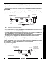
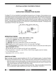
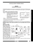
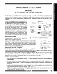
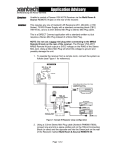
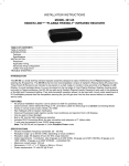
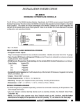
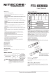
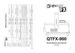
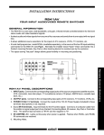
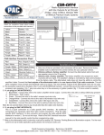
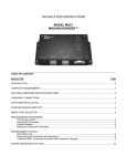
INSTALLATION INSTRUCTIONS 599-00 PULSED SWITCHING MODULE The 599-00 generates momentary (pulsed) outputs in response to an On/Off switched DC input voltage. The pulsed outputs, 100 milliseconds in duration, are triggered during the On and Off transitions of the DC input voltage. The 599-00 was developed primarily to provide momentary inputs for the Model 590-00 Programmable Controller when working with long term DC control voltages. It will work, however, in any application requiring a pulsed output from a switched DC input. IN+ 599-00 OFF IN– PULSED SWITCHING MODULE ON GND GND +12V +12V Controllers ® SYLMAR, CA • MADE IN U.S.A. Fig. 1 The 599-00 Red LED SPECIFICATIONS • Input Control Voltage & Current: (at IN+ & IN– Terminals) 4 to 12 Volts DC @ 1 mA/Volt. • Min. Input Turn-ON & OFF Voltage: 2.5 Volts DC. • Red LED lights with presence of voltage at the IN+ & IN– terminals (+1.4 V or more). • Input Terminals (IN+ & IN–) are Opto-Isolated for floated input applications. • Pulsed Output (100 mS) Voltage & Current (at ON & OFF Terminals): +12 Volts Peak, @ 1 mA.; + 9 Volts Peak, @ 12 mA.; + 6 Volts Peak, @ 25 mA.; + 3 Volts Peak, @ 30 mA. • ON Terminal: (see Fig. 6) Goes active High during Input On transition at the IN+ & IN– terminals. • OFF Terminal: (see Fig. 6) Goes active High during Input OFF transition at the IN+ & IN– terminals. • Power Requirements: 12 VDC @ 30 mA. • Terminals: Screw-type handle wire sizes from 24 to 14 gauge. • Mounting: Flanges, plus supplied screws, permit easy mounting to flat surfaces. • Dimensions: 4-1/4" x 1-7/8" x 1" (108mm x 48mm x 26mm) INSTALLATION Using the 599-00 to Provide Momentary Inputs for the Model 590 Programmable Controller. The 590 Controller was designed to be used with momentary contact switches. In such applications, a button is pressed, the 590 outputs an IR command, and the button is released. If the button is not released, the 590 will either continue to repeat the same IR command or send no signal at all after the initial burst. As long as one key is pressed, subsequent actions will be locked out; the other keys (inputs) will not respond. The 599-00 overcomes this, allowing a system to respond to some change or function in an audio/video system, triggered by automated actions. • For example, if an A/V Receiver is turned ON manually, an IR command sequence can be made to turn a DVD player ON and activate PLAY at the same time. 1 • When the AM/FM receiver is turned OFF manually, an IR command can also STOP the DVD player and turn it OFF. • To do this, the presence or absence of a constant ON and OFF DC voltage must be converted to momentary pulses to properly operate the Model 590. • This can be done by using the Model 599-00 connected as shown in Fig. 2. • By plugging the Model 786-00 power supply into the switched AC outlet on the back of an A/V Receiver, a constant 12 VDC is applied to the 599-00 when the Receiver is powered ON. The 599-00 generates a short pulse (+12V, 100 mSec) at its ON terminal when it first sees +4 to +12V DC at its IN+ and IN– terminals. • Similarly, it will generate a short pulse at its OFF terminal (+12V, 100 mSec) when the +4 to +12 volts drops to 0 volts (the A/V Receiver is turned off). Refer to Fig. 6. • This short pulse operation, therefore, permits momentary switches connected to other inputs on the 590 (such as inputs 1 and 2, as in Fig. 2) to execute other system commands uninhibited. Plug into the Switched AC Outlet + – IN + 599-00 IN – PULSED SWITCHING MODULE GND 786-00 A/V Receiver ON GND +12V Power Supply OFF +12V ® SYLMAR, CA • MADE IN U.S.A. (Most 5 to 12 V DC unregulated power supplies will work) 590-00 Programmable Controller (rear panel) RES DEL SEQ PGM ON + 1 2 3 4 5 6 7 8 1234 BANK 12VDC – + 9 10 11 12 13 14 15 16 O G 12VDC – IR RCVR ® 12VDC EMITTERS 789-44 CONNECTING BLOCK To 120 V AC (unswitched) 786-00 Power +12 VDC Blink IR Emitter Connecting Block STATUS 283M GND (–) 789-44 IR IN DVD Player To Emitters on other system devices +12V DC Ground or "–" return wires. GND Momentary Switches for other system devices Supply Fig. 2 Using a 599-00 to Trigger the Inputs on a 590 Programmable Controller IR from other sources, such as IR Rec'rs, Keypads, etc. Using a Sensing Switch Fig. 3 shows another example of how a DC control voltage is converted to momentary ON and OFF pulses. OFF ON SPST Sensing Switch IN + 599-00 IN – PULSED SWITCHING MODULE GND +12V ® SYLMAR, CA • MADE IN U.S.A. Fig. 3 ON GND +12V • For instance, a special SPST sensing switch, as shown, could be mounted in the springs of an over-stuffed chair. OFF SPST Sensing Switch Application Connect to the 590-00 in the same manner as in Fig. 2. • When someone sits down in the chair, the SPST switch closes, causing the 599-00 to trigger a sequence of IR commands stored in the 590. The IR commands, for instance, could cause the room lights to dim, the drapes to close, and music to emanate from the speakers. 2 599-00 • When the chair is no longer occupied, the SPST switch opens, triggering another set of sequenced commands. These, in turn, could cause the lights to brighten, the drapes to open and the music to turn off. • Many other scenarios are possible, limited only by the imagination and needs of the installer and user. Driving a Relay There are times when you may want to drive a relay directly from the ON/OFF outputs of the 599-00 to trigger a device, such as a power amplifier, drape pulls, screen drops, etc. -- devices that require a momentary dry switch closure. Fig. 4 illustrates how this can be done. 1N4148 786-00 Power Supply Isolation Diodes (see text) (Most 5 to 12 VDC unregulated power supplies will work) + – Plug into the AV System's Switched AC Outlet To device requiring a momentary dry switch closure for activation IN + 599-00 OFF IN – PULSED SWITCHING MODULE ON GND GND +12V +12V N/O – + ® SYLMAR, CA • MADE IN U.S.A. Relay (Coil: 6 VDC @ 20 mA) 781RG 1N4001 Power Supply Fig. 4 Driving a Relay For a Momentary Dry Closure • The DC control voltage may be a power supply adapter connected to the switched outlet of an AV receiver, as illustrated, or any other 4 to 12 VDC controlling source. • The two 1N4148 signal type diodes provide isolation between the ON & OFF outputs, yet combine them so that a momentary pulse drives the relay for both the On and Off transitions. • CAUTION: A 1N4001 diode (or equivelant) must be connected in parallel with the relay coil as shown. This prevents high relay coil back EMF from damaging the 599-00 during switching transients. DC On/Off to Momentary On/Off Some preamps, or A/V control centers, have a 0 to 12 VDC output control port for the express purpose of turning a companion amplifier, with a non-momentary DC control voltage port, On and Off. However, some amplifiers (or other devices), have a control port that requires a momentary pulse to trigger the On/Off condition. The 599-00 is an ideal module for making this conversion. Fig. 5 illustrates how this is done. • The non-momentary DC control voltage from the preamp or other controller, is connected to the IN+ and IN– terminals as shown. From a System's 4 to 12 VDC non-momentary control voltage output + 1N4148 Isolation Diodes (see text) IN + 599-00 IN – PULSED SWITCHING MODULE GND OFF +12V ® SYLMAR, CA • MADE IN U.S.A. 599-00 DC On/Off to a Momentary Pulsed On/Off Trigger + ON GND +12V Fig. 5 To an amplifier or other device requiring a momentary trigger pulse for power On/Off or other type of activation – + 781RG Power Supply To 120 VAC (unswitched) 3 Controllers Back EMF Diode (see CAUTION above) To 120 VAC (unswitched) • The required momentary trigger pulses from the ON/OFF terminals is connected to the device's triggered input terminals. • As in Fig. 4, the two 1N4148 signal type diodes provide isolation between the ON & OFF outputs, yet combine them so that there is a momentary pulse for both the On and Off transitions. • The 599-00 will drive any input that will work with the voltage and current values given for the Pulsed Output (ON & OFF) terminals listed under "SPECIFICATIONS". System "ON" Interval System "OFF" + 4 – 12 V Red LED ON (~1.4 V) INPUT (non-momentary) 0V "ON" Transition (~ 2.5 V) "OFF" Transition (~ 2.5 V) +12 V OUTPUT (momentary) 0V *See "SPECIFICATIONS" Fig. 6 100 mSec (@ 1 mA)* "ON" Terminal "OFF" Terminal Operation Timing Diagram 4-13-00 4 599-00