1
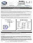
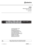
C2R-CHY4
Radio Replacement Interface
with Nav Outputs for all Chrysler
Dodge / Jeep CANbus Vehicles With
or Without Premium Audio Systems
J1850
CRC
Class 2
1 0 0 0 111 0 1111 0 0 1 0 0 11 0 11 0 0
Radio Connection Chart
White / Black
Front L - input
Grey
Front R + input
Grey / Black
Front R - input
Green
Rear L + input
Green / Black
Rear L - input
Purple
Rear R + input
Purple / Black
Rear R - input
CAN Interface Connection Chart:
Red
Acc. Output (1 amp)
Red / White
P.B. Output (-)
Purple / White
VSS Output (Pulse)
Orange / White
Illum. Output (+)
2 11
Front L + input
3
White
4
Antenna On Input
5
Blue
Radio Connections. See aside
Chart for color description.
SWC Interface.
Program for Version 2
Ground
CAN INTERFACE
Black
Accessory Output
+12volts 1amp max.
Battery +12v
Class 2
111 0 1 0 0 0 0 11 0 11 0 111 0 0 11 0 0
Navigation outputs and
Amplifier Remote Input
See Chart for wire color
descriptions.
(Read the Installation Notes before making
connections to the provided radio harness)
Yellow
J1850
11 10 9 8 7 6
EOD
111 0 1 0 0 0 0 11 0 11 0 111 0 0 11 0 0
2 11
Class 2
3
J1850
4
Class 2
5
Arbitration
11 10 9 8 7 6
VPW
1 0 0 0 111 0 1111 0 0 1 0 0 11 0 11 0 0
Chrysler
Radio Specific Steering
Wheel Control Interface
(Sold Separately)
Program SWC
Interface for Version 2.
Installation Notes
1. Only one of the two provided radio harnesses will be used. Remove the factory
installed radio to determine the correct harness for your particular vehicle.
2. Vehicles without a factory amplifier: Connect the aftermarket radio’s front and
Green
Reverse Output (+)
rear speaker wires to the 22 pin plug.
White / Green
SWC Output
3. Vehicles with a factory amplifier: The factory amplifier only accepts two audio
Blue / White
Amp Turn On Input
channels (left and right). The amplifier’s fading is controlled by data communication
from the factory radio. The aftermarket radio does not have the ability to control the
amplifier’s fader. Connect the front outputs of the aftermarket radio to the rear inputs of the 22 pin radio connector. This will
allow navigation voice prompts and Bluetooth calls to be heard. The rear speaker outputs of the aftermarket radio are not used.
4. The accessory output wire is located on the 11 pin CAN INTERFACE harness - connect this wire to the radio’s accessory wire. The
accessory wire supplies +12v, 1 amp max when key is in the accessory or ignition position (fig. 1: If more current is needed).
5. 11 pin plug (to CAN INTERFACE):
1. Blue/White - Connect this wire to the radio’s amplifier remote output. Connect this wire with or without OEM amp present!
2. White/Green - SWC output.
Fig. 1
High Current 12v
(using a SPDT relay)
3. Green - Connect this wire to the radio’s reverse input wire only.
(Fused)
4. Orange/White - Connect this wire to the radio’s Illumination input wire only.
5. Violet/White - Connect this wire to the radio’s VSS input wire only.
85
86
87
12v Acc.
6. Red/White - Connect this wire to the radio’s parking brake input wire only.
Note: Do not connect these wires to any circuit other than the radio’s wire harness.
From
Interface
87a
Ground
6. 11 pin plug (to SWC INTERFACE):
30
This is a quick connection to a radio specific SWC interface. No additional
Diode 1N4005
or equivelant
New High
connections are necessary other than radio control connections. Plug the radio
Current Output
specific SWC interface in to this connector and program the radio specific SWC
interface for version 2. Do not cut the loops. Refer to the SWC interface instruction
manual for the radio specific control function programming order.
7. Refer to the aftermarket radio’s instruction manual for testing VSS, Reverse, Parking Brake and Illumination outputs. For the most
current and Up-to-Date application guide please visit www.pac-audio.com
7-19-10
Pacific Accessory Corporation - Santa Ana, CA 92705
[email protected] • Voice: 866-931-8021 • Fax: 714-835-3233 • www.pac-audio.com
Using the VES & Reverse Camera (if equipped)
Vehicles equipped with a DVD player built into the rear screen assembly:
The C2R-CHY4 will allow the VES DVD player and rear screen to function as if the factory radio were present. A/V will be passed
from the factory DVD player to the rear screen and audio can be heard through the headphones. A/V cannot be passed from the
factory DVD player to the aftermarket head unit.
Vehicles equipped with a stand alone VES DVD Player:
The C2R-CHY4 will allow the VES DVD player and rear screen(s) to function as if the factory radio were present. A/V will be
passed from the factory DVD player to the rear screen(s) and audio can be heard through the headphones. A/V can also be fed
from the VES DVD player into an aftermarket head unit (head unit must support A/V in) with the use of the CHYRVD.
Vehicles not equipped with a VES DVD Player (rear screen(s) only):
In this application the CHYRVD must be used in order to feed A/V into the factory screen(s) from an aftermarket head unit (head
unit must support A/V out). With the CHYRVD, A/V will be passed from the aftermarket head unit to the rear screen(s) and audio
can be heard through the headphones. If you wish to retain the Auxiliary inputs on the rear of the console you must disconnect the
factory wires from the auxiliary input then connect and run your own RCAs into the aftermarket head unit.
Vehicles equipped with a Reverse Camera:
In order to retain the factory reverse camera the CHYRVD must be used to feed video into the aftermarket head unit (head unit
must support reverse camera input).
DISCLAIMER: Under no circumstances shall the manufacturer or the distributors of the C2R-CHY4 be held liable for consequential damages sustained in
connection with the C2R-CHY4. The manufacture and it’s distributors will not, nor will they authorize any representative or any other individual to assume
obligation or liability in relation to the C2R-CHY4 other than its replacement.
7-19-10
Pacific Accessory Corporation - Santa Ana, CA 92705
[email protected] • Voice: 866-931-8021 • Fax: 714-835-3233 • www.pac-audio.com