1
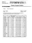
SERVICE MANUAL
Introduction
This manual details the steps necessary to replace many components on the LX810. It is not intended to
be a comprehensive manual for replacing all parts on the LX810. Instead it is broken down into modules or
assemblies. The manual explains how to replace the entire assembly, not specific parts on each assembly.
The assemblies included in the manual are the ones most likely to be damaged or need replacement after
extensive use.
You will need only a few tools to complete these repairs. A T10 Torx screwdriver, a Phillips #1 screwdriver
and a straight screwdriver are required. Long shank screwdrivers work best. For ease of use, the
screwdrivers should be magnetized.
Section
Page
1. Removing the Top Cover ……………………………………………………………………………………… 2
2. Replacing the Printer Module ……………………………………………………………………………….... 4
3. Removing the Front Cover……………………………………………………………………………………... 12
4. Replacing the Label Clamp Assembly………………………………………………………………………… 14
5. Replacing the Ink Pads…………………………………………………………………………………………. 18
A. Replacing the Center Air Filter………………………………………………………………………...18
B. Replacing the left and right side Ink Pads…………………………………………………………… 19
6. Replacing the Feed Motor……………………………………………………………………………………… 21
7. Replacing the Main Board……………………………………………………………………………………… 23
8. Replacing the Loop Sensor…………………………………………………………………………………….. 25
9. Removing a Jam in the Label Sensor……………………………………………………………………….. 26
Appendix A – Parts List………………………………………………………………………………………….. 27
-1-
Section 1: Removing the Top Cover
1. Open the Top Cover.
2. Remove two Phillips Head screws as shown.
3. Close the Top Cover.
4. Remove two Phillips Head screws as shown.
5. Pull the Top Cover back until you see a gap as
shown.
-2-
6. Open the Top Cover.
7. Grab the cover by the bottom and tilt it upward.
8. Pull the cover from the base.
-3-
Section 2: Replacing the Print Module
• Part Number 660200
1. Remove the Top Cover. Refer to Section 1 for
instructions.
2. Remove two T10 Torx screws as shown.
3. Remove the USB Cable from the Main Board.
4. Remove three Phillips screws as shown.
5. Remove the USB Connection.
6. Remove the metal Board Cover.
(Steps 4-6 are not necessary for units with
Serial Numbers greater than 2050300000. It is
necessary to remove this cover on earlier models
because it allows access to a screw that is not present
on later models)
-4-
7. Remove two screws from the Star Wheel Plate
Assembly.
8. Remove the Assembly.
9. Remove three T10 torx screws from Upper
Clamp Plate.
10. Remove Upper Clamp Plate.
11. Remove Exit Shaft.
-5-
12. Use a flat screwdriver to gently pry the shaft up
enough to grab it with your finger (Step 12).
13. Grab the shaft with your left hand.
14. Press down on the far right side of the shaft with
your right hand and pull up and to the left in the middle
until the shaft is free from its mounting holes.
15. Unhook the shaft from the belt on the left side.
-6-
16. Disconnect the connections J14 (Lex Power) and
J5 (Lex Ctrl) from the main board.
17. Remove J14 and J5 wires from the wire harness.
18. Remove the motor wires from the wire harness.
-7-
19. Move the print carriage to the middle of the print
area to access the print module screws.
20. Remove right Print Module mount screw.
21. Loosen this screw.
(This step is not necessary for units with
Serial Numbers greater than 2050300000)
-8-
22. Remove two left side mount screws.
23. Slide the module forward slightly and tip
the front portion up in order to remove it from the
printer.
The parts shown to the right were removed and should
be reinstalled in reverse order.
Note: Print Module is shown with metal Board Cover
removed. The new Print Module will have the Board
Cover attached. It will be necessary to remove this
cover in order to install the new module for units with
serial numbers less than 2050300000.
When replacing the print module take note of the
screw and notched pins and the corresponding screw
notch and tabs on both sides of the print module. The
tabs should be placed into the notched pins on
both sides of the Print Module.
Screw.
Right Side Notched Pin.
-9-
Screw Notch.
Right Side Tab.
Left Side Notched Pin.
Right Side Tab.
- 10 -
When replacing the exit shaft, you will need to hook
the notched edge of the shaft into the belt before
snapping the roller back into place.
Notched side should be installed to the left.
- 11 -
Section 3: Removing the Front Cover
Removing the Front cover is necessary to access the
Label Clamping Assembly and to replace the left and
right ink pads.
1. Remove the Top Cover (Refer to Section 1).
2. Remove two T10 Torx screws.
3. Loosen the Phillips head screw on the bottom of the
Printer.
4. Loosen the top Phillips head screw which is
attached to the Front Cover from behind.
Note: When replacing this screw, do not over
tighten! Over tightening will result in problems
replacing the Top Cover.
- 12 -
5. Loosen the bottom Phillips head screw which is
attached to the Front Cover from behind.
Note: When replacing this screw, do not over
tighten! Over tightening will result in problems
replacing the Top Cover.
6. Disconnect J1 (Frnt Panel) from the main board.
7. Remove wire from wire harness.
8. Remove the Front Cover.
- 13 -
Section 4: Replacing the Label Clamp Assembly
• Part Number 660030
1. Remove the Front Cover (Refer to Section 3 for
Instructions)
2. The label Clamp Assembly is secured by four T10
Torx screws.
3. Remove the two right side torx screws.
4. Remove the two left side torx screws.
- 14 -
5. Disconnect J18 (Label Clamp Sensor) and J2 (Label
Clamp Motor) from the Main Board.
6. Tip the Label Clamp Assembly forward.
7. Pull the Assembly up and out and
set it on the table.
8. Remove the wires from the unit by feeding the main
board connections through the hole in the metal frame.
(Remove wires from wire harness)
- 15 -
9. Locate the new label clamp assembly.
10. Feed the connectors through the hole in the metal
frame. (Put the wires back into the wire harness)
11. Set the Assembly in place as shown.
12. Tip the Assembly up and partially into place.
13. Make sure the bottom edge is resting on the metal
base of the Printer and not on an ink pad.
- 16 -
14. To complete the installation, snap the metal tabs
under the metal roller guide.
15. When reconnecting wires to the main board make
sure J2 (Label Clamp Motor) is correctly connected. It
is possible to reconnect it up side down causing the
clamp to be on when it should be off.
The red wire should be on the left – Black should
be on the right.
16. Replace the Torx screws, the Front Cover and the
Top Cover.
- 17 -
Section 5: Replacing the Ink Pads
•
Part Number 074220 (Contains Right and Left Side Pads and Center Air Filter Pad)
A. Replacing the Center Air Filter Pad
1. Turn the printer on its side so you can access the
bottom.
2. Remove two Phillips head screws as shown.
3. Slide the Air Filter Frame out of the base.
4. Remove the used filter.
- 18 -
5. Place the new filter in the slot.
6. Replace the Air Filter Holder.
7. Replace the screws.
B. Replacing the left and right side pads.
The left and right side ink pads come in a kit with the
Center Air Filter. The pads are shown on the right.
It is possible to install the left and right side pads by
removing the air filter frame (Section 5A) and blindly
removing them from the pins on the base of the unit.
However, it may be easier to install the pads using the
following procedure.
To install the pads you will need to remove the Top
Cover, Front Cover and the Label Clamp Assembly.
Refer to sections 1, 3 and 4 respectively. It is possible
to replace the pads with out removing the Label Clamp
Assembly (Section 4). However, in the following
photos it has been removed to allow for a better view.
1. Remove the saturated left and right side pads from
the printer base.
The pads are held in place by three straight pins and
one pin with a washer on top. The washer pin holds
the pad down so it will take slightly more effort to move
the pad over this pin.
- 19 -
2. Place the new pads over the pins. The pads have
holes that correspond to the pins.
3. A correctly installed ink pad is shown on the right.
- 20 -
Section 6: Replacing the Feed Motor
• Part Number 660101
1. Remove the Top Cover as described in Section 1.
2. Locate the Feed Motor on the left side of the unit
above the main board.
3. Remove Power from the main board.
4. Remove two Phillips head screws from the top left
and bottom right.
5. Disconnect the belt from the pulley on the motor.
- 21 -
6. Install the new motor.
7. Hook the pulley back into the belt.
8. Replace the Motor Mount Screws.
9. Loosen three Motor Bracket Mount screws ¾ turn
each. Twist the motor assembly free and then allow
the spring to tension the belt. Retighten screws
starting with the lower right and proceeding in a
clockwise direction.
10. Reattached power to the main board.
11. Replace the Top Cover.
- 22 -
Section 7: Replacing the Main Board
• Part Number 140400
1. Remove Top Cover (Refer to Instructions in Section
1).
2. Remove all connections from the main board.
TIP: It may be helpful to label the loose connectors
with the Junction letter codes. (Example - J18)
3. Remove the four T10 torx screws located at each
corner of the main board.
4. Tip the board out and pull up as shown.
You must clear the power switch on the left before you
can completely remove the board.
- 23 -
5. Locate the new main board.
6. Reattach the connections.
Note: All of the wire connectors can only be correctly
seated in one connection on the main board. Each
connector type as a different number of pins.
The 4 white connectors fit on the short pins
The 5 blue connectors fit on the long pins.
One orange connection fits on the long pins.
Three connections on the main board
are left empty:
• J10
• J17
• Test Port
- 24 -
Section 8: Replacing the Loop Sensor
• Part Number 140402,140403
1. Remove the Top Cover (See section 1 for
Instructions).
2. Disconnect the Label Loop Sensor (J19) connector
from the main board.
3. Disconnect the Loop LED (J20) connector from the
main board.
4. Remove two phillips screws securing the loop
sensor bracket as shown.
5. Remove the loop sensor bracket. (Feed the
connectors through from the main board area.)
6. Remove two torx screws from both the LED(front)
and the sensor (rear).
7. Locate new sensors. Replace screws and
connectors. Reattach loop sensor bracket.
Front
Rear
- 25 -
Section 9: Removing a Jam in the Label Sensor
1. Remove the Top Cover (Refer to Section 1 for
Instructions).
2. Remove the Printer Module (Refer to Section 2 for
Instructions).
3. Remove the two T10 torx screws to access the area
under the label sensor.
4. Remove the top portion of the TOF sensor housing.
5. Remove the jammed label stock.
6. Clean the metal components of any label debris
with Isopropyl alcohol.
7. Reinstall all parts.
- 26 -
Appendix A - Parts List
Part Number
Description
Price
074220
Kit-LX810 Ink Pad Replacement
$12.32
660200
Module-LX810 Replacement Printer
$310.44
660030
Assembly - Label Clamp
$217.62
660101
Assembly - Feed Motor
$113.04
660314
Roller-Label Feed
$95.28
140400
LX810 Main Board
$213.30
140403
LX810 Loop Sensor
$17.93
140402
LX810 Loop LED
$7.32
140392
LX810 EDGE CLAMP SNS
$8.46
Boxing / Accessories
052209
CABLE-USB A-B 6'
$4.50
053376
CARTRIDGE-LX/BP COLOR DYE
$47.95
053377
CARTRIDGE-LX/BP BLACK DYE
$42.95
053020
CARTRIDGE-LX/BP BLACK PIGMENT
$42.95
130063
POWER CORD-BLACK
$9.12
150404
PWR SUPPLY EXT 12V - 60W
$55.50
062067
Supply Pack LX810 (Manual Etc.)
$14.28
260374
BOX-LX810 OUTER
$24.30
260376
END CAP SET-LX810
$42.00
510943
MANUAL LX810
$6.60
510929
QUICK START-LX810
$2.34
074890
LBL STOCK-STARTER 6"X4"
$20.28
*Prices are subject to change with out notice. Please contact the Supplies Dept. for the latest pricing information 1-800-797-2772
- 27 -