1
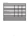
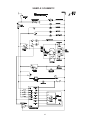
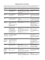
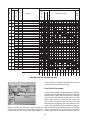
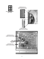
QUICK REFERENCE SHEET
Component resistance chart.
Electrical component
Water valve solenoids
Door lock solenoid
Timer motor
Pump motor
Dispenser valve soleniods
M1 TO M2
M2 TO M3
Motor
M1 TO M3
M5 TO M6
ATC
Resistance Ω
@ 77° F (25°C)
880 ± 10%
380 ± 10%
2425 ± 6%
15 ± 7%
1100 ± 7%
2.6 ± 7%
2.6 ± 7%
2.6 ± 7%
184 ± 7%
50K ± 2%
Water fill height 4 5/8 ± 3/8 IN. (11.75 ± 0.95 CM)
No load, start position of permanent press cycle.
Electrical requirements.
Circuit - Individual, properly polarized and grounded
15 amp. branch circuit fused with 15 amp. time delay
fuse or circuit breaker.
Incoming water pressure.
30 and 120 pounds per square inch (maximum
unbalance pressure, hot vs. cold, 10 psi.)
Drain requirements.
Drain capable of eliminating 17 gals (64.3 L) per minute.
A standpipe diameter of 1-1/4 in. (3.18 cm) minimum.
The standpipe height above the floor should be:
Motor.
Minimum height:
24 in. (61 cm)
Maximum height:
96 in. (244 cm)
Agitate wattage - Max 200
Spin wattage - Max 475
8