1
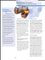
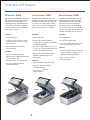
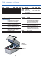
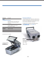
AgilentTechnologies’TS-50
RF Shielded Test Fixtures
Test Fixture Solutions
for Mobile Phones
and RF/Wireless Devices
• Fast, Easy Development
of Phone Test Fixtures
• Use in Production Test, Quality Assurance,
or Design Verification
• Works with Agilent Test Equipment
as Well as Other Manufacturers’
RF or Mobile Phone Testers
Introducing Agilent Technologies’
TS-50 Family of RF Shielded Test Fixtures.
RF Test Fixtures —
’’Home-Made” Hassles
Or...
Developing a test fixture for
radio frequency (RF) devices — such as
mobile phones and other wireless
devices — can be an expensive, tedious,
and time-consuming task. Besides
...A “Head-Start” with Pre-Built Kits
For Many Test Systems
designing and installing a test system,
The Agilent TS-50 Family of RF/Mobile
Phone Test Fixtures are kits containing
key components and options to create
reliable, high-quality fixtures for
mobile phones, phone printed circuit
boards (PCBs), and other RF devices.
For phones, you need only add connections, such as the phone’s system connector, battery connections, and
RF/antenna. For PCBs, you need to
create a probe plate and probes for
your specific board. The TS-50 family
leaves out nothing essential. You can
get the following capabilities:
The Agilent TS-50 Family of RF/Mobile
Phone Test Fixtures is highly versatile
and adaptable. They are designed to
work optimally with Agilent test equipment — e.g., the RF Test Sets and the
TS-5500 Cellular Phone Functional Test
Platforms — a complete mobile phone
offering used by leading cellular phone
manufacturers. However, they will also
work with other manufacturer’s RF or
mobile phone testers. This gives you
the widest flexibility possible, allowing
you to use virtually any make or model
of test system on the market — including, most likely, the one you have!
now you must develop a complete, highquality fixture as well! Sometimes your
best option is to design a fixture and hire
out the implementation. Sometimes, it is
best to adapt or modify an existing fixture
— but even then, there usually is not
enough time to thoroughly test and
qualify the design. Hence, final designs
may not be robust, so reliability issues
may show up in production.
Is there an answer?
• Rugged RF-shielded enclosure with
secure closing/latching mechanism
There is.
• Optional adjustable “nest” to hold
the phone
Now you can create complete, high-
• Enclosure with board-press mechanism for probing printed circuit
boards under test
quality RF/mobile phone test fixtures —
and do it in a matter of days, not weeks
• Optional fixture electronics board to
filter signals and provide level-shifted
RS-232 or user-specified connections
to the tested phone or phone PCB
or months. Introducing the TS-50 family
of RF/Mobile Phone Test Fixtures.
• Optional cables (standard D-sub) to
connect the TS-50 to your test system
• Optional audio capability, including
speaker and microphone pick-ups,
as well as signal amplification
and shielding
2
Fast Fixture Development
Using the Agilent TS-50, you can create
a custom fixture for testing virtually
any assembled phone, RF device, or
phone PCB. For fast prototype phone
testing, you start with the RF enclosure
and the phone quick-nest option. The
quick-nest option is robust enough for
use in manual production lines. Then,
to quickly complete the fixture nest for
final test, simply connect the phone’s
system connector to the fixture connectors. The RF connection from the
phone feeds through the fixture to the
RF test equipment. To add optional
audio capability, attach the speaker and
microphone to the quick-nest and position them under the phone. For testing
phone PCB’s, start with the RF enclosure with the board-press mechanism.
For both assembled-phone and phone
PCBs, the shielded RF enclosure and
routing of test signals are done for you.
Fast, Safe Semi-Automatic Test
Compact, Lightweight
A Word to Agilent's TS-5500 Users...
Semi-automatic (that is, human-loaded)
testing of mobile phones and PCBs is
fast and easy with Agilent TS-50 fixtures. To use a fixture, the test operator
simply opens the lid, connects the
phone to the cable(s), places the phone
in the quick-nest, closes the lid, and the
system software senses a micro-switch
closure and starts automatically. That
is all there is to it. After the test is complete, the operator removes the phone
and inserts the next one. When doing
phone PCB test, the operator closes the
lid, automatically pushing the probe
pins into the appropriate junctures on
the PCB. Pneumatics are not needed —
mechanical action alone creates stable,
reliable connections.
The Agilent TS-50 fixture is small in
size: 300 mm (11.81 in) wide, 450 mm
(17.7in) deep, 275 mm high. Two fixtures can be placed side-by-side in
front of a standard 19 in. (482.6 mm)
rack. Inside, the fixture has space to
test phones or other RF devices as
large as 45 mm (1.77 in.) deep, 90 mm
(3.54 in.) wide, and 300 mm (11.81 in.)
long. The fixture weighs approximately
20 lbs. fully assembled, so is easily
transportable without a rack or cart.
In addition to its own features, the
TS-50 family provides the following
benefits to users of the Agilent TS-5500
Family of Cellular Phone Functional
Test Platforms:
Agilent's Worldwide Service and Support
• Overall system self-test, including
fixture, is provided with the
Agilent TS-5530
Low Maintenance
The Agilent TS-50 fixture’s rugged
design and reliable mechanisms minimize your test (and production) downtime. This solid fixture has a proven
track record, since it is based on
Agilent’s custom fixture designs for the
last few years. Only a few mechanical
parts must be replaced on a regular
basis (the exact maintenance cycle is
dependent on the phone connector).
A loop-back cable, provided with the
Agilent TS-50, allows for maintenance
and diagnostics tests from the tester
through the internal circuitry and
back to the test system.
• Two fixtures can sit on a work
surface in front of a two-up Agilent
TS-5500 system, providing extremely
efficient use of floor space
• Cables connecting the TS-50 directly
to the Agilent TS-5500 test system
are available
Like all Agilent test systems and equipment, the TS-50 Family of RF/Mobile
Phone Test Fixtures enjoys the worldrenowned service and support that are
an Agilent trademark — around the
globe. Support (including repair) is
faster and more economical than with
home-made or “one-of-a-kind” devices.
Agilent's service and support can help
ensure maximum uptime for your
entire system.
• The Agilent TS-5500 operator
interface and RF path calibration
defaults to this fixture
• The Agilent TS-5500 test system
has software and hardware that
interfaces to the E8705B and
E8706B PCB
Agilent’s TS-50 fixtures
are designed to work
Fixture Re-use — A Huge Savings
The Agilent TS-50 fixture can be reconfigured and used with new products —
a major cost savings. Now you don’t
have to design a completely new test
fixture for every new phone! You need
only add new cables to the phone and
re-adjust or change the phone quicknest. For a new PCB, you can re-use
the board fixture by creating a new
probe plate with pins, similar to the
process for in-circuit board testers.
This reusability also means savings on
fixtures for prototypes in the design
verification or pilot production phase.
with Agilent 892x and
8960 series test sets,
Agilent TS-5500 cellular
phone functional test
platforms (right), and
with any other RF or
mobile phone testers
3
TS-50 Family of RF Enclosures
RF Enclosure - E8704B
Final Test Fixture - E8705B
Board Test Fixture - E8706B
The TS-50 model E8704B is simply the
RF-shielded enclosure that could be
used in testing many RF devices,
including phones. This RF-shielded
enclosure could easily be adapted
for many different test systems and
TS-50 options added.
The TS-50 model E8705B is the RFshielded enclosure that should be used
in testing assembled phones. Options
necessary for nesting, signal routing,
audio connections and cabling to the
TS-5500 test systems are available.
The TS-50 model E8706B is the RFshielded enclosure used in testing
wireless/RF PC boards, including
phone PC boards. A board press
mechanism is the base for holding
the PC board. Options are available
for probe plate kits, signal routing and
cabling to the TS-5500 test systems.
Includes:
Includes:
Includes:
• Enclosure Shell
• Enclosure Shell
• Enclosure Shell
• Rear Cover Plate with one 25 pin
D-Sub Connector and one N-type
RF Connector
• Fixture Electronics Board for
Routing Phone Signals, Level-Shifting
and Filtering Signals
• Board Press Mechanism
• One Blank Rear Cover Plate
• Rear Cover Plate with one 9-pin, one
15-pin, one 25-pin D-Sub Connectors
and one N-type RF Connector
• Nest Base Plate
Options:
• RF Absorber Nest Environment to
Eliminate Standing Wave and
Reflections
• Opt. 005 RF Absorber Nest
Environment to Eliminate Standing
Wave and Reflections
• Opt. 002 Audio Components Kit
Options:
• Opt. 003 Quick-Nest Kit for
assembled phones
• Opt. 002 Audio Components Kit
• Rear Cover Plate with Connectors
and one N-type RF Connector
Options:
• Opt. 001 Fixture Electronics Board
for Routing Phone Signals, LevelShifting and Filtering Signals
• Opt. 030/050 Cables to
TS-5500 Systems
• Opt. 003 Quick-Nest Kit for
assembled phones
• Opt. 030/050 Cables to
TS-5500 Systems
E8704B
E8705B
4
E8706B
Completing the Fixtures
Characteristics
A complete test fixture must be created
from the TS-50 fixtures, since they are
RF-shielded enclosures plus various
kits and components. Complete fixture
solutions can be provided by Agilent’s
custom systems teams, your test engineering team or a third party vendor.
Typical RF Shielding
E8704B
E8705B
E8706B
Optional Audio
600 MHz-2.5 GHz (dB)
>50 dB
>65 dB
>45 dB
• Source and measurement pairs used
800 MHz-1.0 GHz (dB)
>60 dB
>65 dB
>60 dB
1.7 GHz-2.0 GHz (dB)
>50 dB
>65 dB
>50 dB
Completing the RF Enclosure-Only (E8704B)
or the Final Test Fixture (E8705B) Products
The test developer must provide:
• Phone Connections including System
Connector, Level-shifting, RF, Phone
Power, SIMM
connectors mentioned above
• Final assembled phone or
board-level test?
Choose final test or board test fixture
Decide on nesting option or custom
nesting for assembled phone
Exterior Dimensions for all Fixtures
Working Space Dimensions
• Besides the RF enclosure, any additional
RF shielding and testing needed?
Consider RF Absorber Environment
E8704B with no Options:
390 mm long x 185 mm wide x 180 mm high
• Audio or acoustic tests required?
E8704B with RF Absorber:
310 mm long x 175 mm wide x 85 mm high
• Choose I/O resources (RF, power, digital,
RS-232) required for phone test:
• Characterization of the RF Path,
Acoustics, Serial/Digital Lines
E8705B:
310 mm long x 175 mm wide x 8 5 mm high
• Device-specific electronics, e.g.
RF/antenna coupler, switching
E8706B:
325.9 mm long (12.8”) x 215.84 mm wide (8.49”)
for single-sided PC boards, double-sided
boards will be slightly less
• Probe Plate, probes, guide pins
and gasketing for specific boardunder-test
To decide on the test fixture configuration to
best suit your needs, consider the following:
E8706B was tested with Board Press and
Fixture Electronics Board Options installed
and TS-5530 cables attached.
• Absorption Materials, specifically RF
and Audio (optional kit on E8704B)
Completing the Board Test Fixture
(E8706B)
Choosing the Best TS-50 Configuration
E8705B was tested with RF Absorber and
Fixture Electronics Board Options installed
and TS-5530 cables attached.
300 mm (11.81in.) wide
450 mm (17.70 in.) long
275 mm (10.83 in.) high
• Cabling to the test system (optional
cables for connecting the E8705B
with the TS-5500 test system)
• All connections made through data
E8704B was tested without options or cables.
• Audio Testing including: Speaker,
Mic, Cables (optional kit)
• Nesting to physically hold the deviceunder-test and make electrical
connections (optional kit)
for fixture speaker, microphone, phone interface connector, and miscellaneous purposes
Consider Audio Components Kit
Connectors to plug into phone
Crimp tools to attach connector
to TS-50 fixture/phone cable
• Map the I/O required to the tester
resources
• Choose type of cables to the tester:
Weight
Cables to Agilent TS-5500
(available option)
Including Standard Options
E8704B 16 lbs. (7.26kg)
E8705B 27 lbs. (12.25kg)
E8706B 20 lbs. (9.07kg)
Build custom cables to other testers
Customization
Connectors
RF:
N-type (External) to
SMA (Internal to Fixture)
• Phone Connections including
System Connector, Level-shifting,
RF, Board Power, SIMM
Data:
RF-filtered 25-Pin D-Sub
Power:
RF-filtered 15-Pin D-Sub
(E8705B and E8706B)
• Device-Specific Electronics,
e.g. Capacitor for Voltage Sag
Serial:
RF-filtered 9-Pin D-Sub
(E8705B and E8706B)
For special customization requirements, you
can start with the Agilent TS-50 RF enclosure
and design the cabling, nest and other
electronics. Agilent can provide design and
implementation services to tailor the fixture
enclosure to meet your needs.
• Connections to Test System,
e.g. Shielded RF Cables
• RF Path Characterization
5
TS-50 Configurations and Options
Option
Description
Option 001
Fixture Electronics Board
N/A
Option 002
Audio Test Components Kit
Optional
Option 003
Quick Nest Kit
Optional
Option 005
RF Absorber Nest
Option 006
Blank Rear Plate
Model/Option
E8704B
E8705B
E8706B
Option
Description
E8704B
E8705B
E8706B
Included
Optional
Optional
N/A
Options
030/ 050
Cables for
TS-5500/TS-5530
N/A
Optional
Optional
Optional
N/A
Option S01
Optional
Optional
Optional
Included
N/A
Optional
Optional
Optional
Fixture Service Kit
Optional
(Includes spare gas cylinders,
D-Sub connectors, EMI gasket
and service manual.)
Description
Model/Option
E8704B:
TS-50 RF-Shielded Enclosure
(RF-Shielded Enclosure with RF connector and
25-pin filtered connector in replaceable rear
plate. Additional blank rear plate supplied.)
Option 002
AudioTest Components Kit
(Includes speaker and microphone pick-ups.)
Description
E8705B:
TS-50 RF Final Fixture Kit
(Consists of RF-shielded enclosure, RF Absorber
Nest environment, Fixture Electronics Board for
filtering and level shifting and rear plate with
standard connectors.)
Option 002
Quick-Nest Kit
(A kit to create a mobile phone nest that can be
reconfigured with hand tools to fit most phones.)
Audio Test Adapter Kit
(Includes speaker and microphone pick-ups.)
Option 003
RF Absorber Nest Environment
(Inner box environment designed to improve
isolation and create a resonance-free cavity,
ideal for over-the-air testing.)
Quick-Nest Kit
(A kit to create a mobile phone nest that can be
reconfigured with hand tools to fit most phones.)
Option 006
Additional Blank Rear Plate
Option 030
Cables for TS-5530
Option 006
Additional Blank Rear Plate
Option 050
Cables for TS-5550
Option 0BN
Assembly/Service Manual
Option 0BN
Assembly/Service Manual
Option 003
Option 005
Option 005
RF Absorber Nest
Option 003
Quick-Nest Kit
6
Model/Option
Description
E8706B:
TS-50 RF Board Test Fixture Kit
(RF-Shielded Enclosure, board compression
mechanism, and rear plate with standard
connectors.)
Option 001
Fixture Electronics Board
(Includes PC Board for routing signals,
filtering and level shifting.)
Option 006
Additional Blank Rear Plate
Option 030
Cables for TS-5530
Option 050
Cables for TS-5550
Option 0BN
Assembly/Service Manual
Interfacing to the Electronics
A complete test fixture electronics solution can be created using a general purpose 12-Bit digital card to control the line and internal resources
in the fixtures.The TS-5500 digital I/O and software library can also be
used as an interface to the electronics for the fixtures.
For additional technical information on the TS-50 family of fixtures,
go to www.agilent.com and click on Products then
Test and Measurements.
Quantity discounts are available.
Standard E8705B
Rear Plate
A blank rear plate cover is
shipped with the fixture and
can be customized for any
interface including:
Third Party Customization
Hard-Tooled Nest
(Pneumatics Supported)
• Air
• Power
• Analog
• RF
• Digital
• Etc.
7
Agilent Technologies’ Test and
Measurement Support, Services, and
Assistance
Agilent Technologies aims to maximize the value
you receive, while minimizing your risk. We strive
to ensure you get the test and measurement
capabilities you paid for and obtain the support
you need. Our extensive support resources and
services can help you choose the right Agilent
products for your applications and apply them
successfully. Every instrument and system we
sell has a global warranty. Support is available
for at least five years beyond the production life
of the product. Two concepts underlie Agilent's
overall support policy: "Our Promise" and "Your
Advantage."
Our Promise
Our Promise means your Agilent test and measurement equipment will meet its advertised performance and functionality. When you are choosing
new equipment, we will help you with product
information, including realistic performance specifications and practical recommendations from
experienced test engineers. When you use
Agilent equipment, we can verify it works properly,
help with product operation, and provide basic
measurement assistance for the use of specified
capabilities, at no extra cost, upon request. Many
self-help tools are available.
For more assistance
with your test & measurement needs go to
www.agilent.com/find/assist.
Or contact the test and measurement
experts at Agilent Technologies
(During normal business hours)
United States:
(tel) 1 800 452 4844
Canada:
(tel) 1 877 894 4414
(fax) (905) 206 4120
Europe:
(tel) (31 20) 547 2000
Japan:
(tel) (81) 426 56 7832
(fax) (81) 426 56 7840
Latin America:
(tel) (305) 267 4245
(fax) (305) 267 4286
Australia:
(tel) 1 800 629 485
(fax) (61 3) 9272 0749
New Zealand:
(tel) 0 800 738 378
(fax) 64 4 495 8950
Asia Pacific:
(tel) (852) 3197 7777
(fax) (852) 2506 9284
Your Advantage
Your Advantage means Agilent offers a wide
range of additional expert test and measurement
services, which you can purchase according to
your unique technical and business needs. Solve
problems efficiently and gain a competitive edge
by contracting with us for calibration, extra-cost
upgrades, out-of-warranty repairs, and on-site
education and training, as well as design, system
integration, project management, and other
professional engineering services. Experienced
Agilent engineers and technicians worldwide can
help you maximize your productivity, optimize the
return on investment of your Agilent instruments
and systems, and obtain dependable measurement accuracy for the life of our products.
Product specifications and descriptions in this
document subject to change without notice.
Copyright © 2000 Agilent Technologies
Printed in USA 06/00
5968-6858E