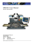
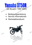
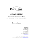
1
DRS24C & R Series
Temperature Controller Replacement
Section 6.0
Replacing your Athena or Cal 9300 temperature
controller. Also, upgrading from Athena to Cal 9300
CONTENTS
6.01
6.02
Athena & Cal 9300 replacement ...........2-3
Cal 9300 upgrade ..................................4-8
☛ BEFORE YOU START:
Read instructions thoroughly before beginning.
ELECTRICAL WARNING:
POWER DOWN DRS24 AND DISCONNECT
FROM POWER SOURCE.
CHECKLIST:
The following items will be needed in this section.
Athena temperature controller
part no. 9002.11.000
Cal 9300 temperature controller
part no. 9002.11.015
For Upgrading only:
Phillips screwdriver
Small straight blade screwdriver
Metric & American Allen wrenches
Metal file
For technical problems, please contact the Air-Vac technical service department at:
Air-Vac Engineering Company, Inc.
30 Progress Avenue • Seymour, CT 06483
Phone: 203-888-9900 • Fax: 203-888-1145
e-mail: [email protected] • www.air-vac-eng.com • 03/26/01
DRS24 Technical Service Manual
Section 6.0 : Temperature Controller Replacement
6.01 Athena & Cal 9300 Replacement
!
VERIFY DRS24 IS DISCONNECTED FROM THE POWER SOURCE.
IMPORTANT
NOTE
STEPS:
☛
The temperature controllers are located in the DRS24 right box (A), (fig.1).
1
Remove the 10/32” button head screw (B), (fig.1), and swing right box open.
B
A
Fig. 1
NOTE
☛
The remaining steps will be performed assuming you are located behind the DRS24.
2
Determine if you have Athena controllers (C), (fig.2), or Cal 9300 controllers (D).
Fig. 2
C
Athena
D
Cal 9300
2
DRS24 Technical Service Manual
NOTE
!
Section 6.0 : Temperature Controller Replacement
Each type of controller has a removable bezel and circuit board assembly (E), (fig.3).
The controller sleeve (F) stays in the machine during controller removal.
☛
ELECTROSTATIC PRECAUTIONS SHOULD BE OBSERVED WHEN HANDLING THE
CONTROLLER OUTSIDE OF THE SLEEVE.
IMPORTANT
3
✰ TIP:
Grasp left and right side controller face grips (G), (fig.3), and firmly squeeze in and slide
controller out of the sleeve.
While pulling out the controller, a gentle, side to side rocking motion will make removal easier.
F
E
Fig. 3
G
4
Remove your new controller from its anti-static packaging and carefully install into the sleeve.
It should snap in when fully seated.
5
Place old controller into anti-static packaging.
6
Please refer to the instructions included with your new temperature controller for programming
details.
3
DRS24 Technical Service Manual
Section 6.0 : Temperature Controller Replacement
6.02 Cal 9300 Upgrade
!
VERIFY DRS24 IS DISCONNECTED FROM THE POWER SOURCE.
IMPORTANT
NOTE
STEPS:
☛
The temperature controllers are located in the DRS24 right box (A), (fig.1).
1
Remove the 10/32” button head screw (B), (fig.1), and swing left box open.
B
A
Fig. 1
NOTE
☛
The remaining steps will be performed assuming you are located behind the DRS24.
2
Remove the four 10-32 low head screws (C), (fig.2), with a 3/32” Allen wrench.
3
Carefully lift the sub plate assembly (D) out of the right box and rest on top of power panel.
4
Squeeze the hinge pins (E) together to release the left box and then lower box to bench.
Remove lid support pin (F) to allow box to sit flat on bench.
5
With the left box cover sitting on the bench next to the machine, flip the entire sub-plate
assembly (D) back over and rest on top of cover (fig. 3, page 5).
C
Fig. 2
E
D
F
4
DRS24 Technical Service Manual
Section 6.0 : Temperature Controller Replacement
4
Remove the four M4 screws (G), (fig.3), with a 3mm Allen wrench and then remove the wire
ties holding the harness.
5
Carefully lift the riser plate assembly (H) off of the sub plate assembly and flip over for access
to the Athena controller rear wire connections.
NOTE
☛
You can re-install two M4 screws (G) into the sub plate to hold the riser plate upside
down in place.
NOTE
☛
Remove and replace one controller at a time so you do not get the wire connections
mixed up.
G
H
Fig. 3
Cover
6
NOTE
☛
Remove the wires from the Athena controller (figure 4) with a phillips head screwdriver.
The wire colors on terminals 13, 14 & 6 may be different than indicated in figure 4
(make a note if they are different).
Red
Fig. 4
Black
POS - White/Red
1
6
NEG - White/Black
2
7
13
Yellow
14
3
8
11
12
4
9
5
10
}
Thermocouple
Black
Light Blue
5
DRS24 Technical Service Manual
NOTE
Section 6.0 : Temperature Controller Replacement
7
Gently slide a thin straight blade screwdriver behind the locking tabs of the Athena retaining
ring (I), (fig.5), pry up and slide the ring down several “clicks”. Repeat, alternating sides, until
the retaining ring slides off. Remove Athena (J) from cutout.
8
Insert the new Cal 9300 controller into the same cutout, making sure that the face is orientated properly (fig.6).
☛
You made need to use a file to make the cutout larger.
9
Slip the retaining ring (I) back over the Cal 9300 sleeve and lock against the riser plate (K).
Fig. 5
I
K
J
Fig. 6
6
DRS24 Technical Service Manual
NOTE
NOTE
For wire connection steps 10-17, refer to figure 7 on page 8. If the wire lengths are too
short, it may be necessary to splice on additional wire lengths by soldering and adding
heat shrink tubing over the splice. Remove spade lugsfrom the end of wires and strip
insulation back approximately 3/16”.
☛
☛
Section 6.0 : Temperature Controller Replacement
10
Connect white/red wire (Athena terminal 1) to Cal 9300 terminal 3.
11
Connect white/black wire (Athena terminal 2) to Cal 9300 terminal 4.
12
Connect yellow wire (Athena terminal 9) to Cal 9300 terminal 1.
13
Connect red wire (Athena terminal 10) to Cal 9300 terminal 2.
14
Connee6 thick black wire (Athena terminal 11) to Cal 9300 terminal 7.
15
Connect thick light blue wire (Athena terminal 12) to Cal 9300 terminal 8.
16
Connect red wire (Athena terminal 13) to Cal 9300 terminal 10.
17
Connect black wire (Athena terminal 14) to Cal 9300 terminal 11.
18
Repeat steps 10-17 for the remaining Athena controller(s) to be upgraded. See complete
diagram for all wire colors and numbers (fig. 7, page 8).
If you have a single diffuser with only two controllers, make sure the wires for the
center (left diffuser) Athena are secured and the ends are shrink wrapped to prevent
grounding or shorting.
7
DRS24 Technical Service Manual
Section 6.0 : Temperature Controller Replacement
Fig. 7 - Athena & Cal 9300 Temperature Controller Hookup (rear view)
POS White/ 80
Athena #3
Athena #2
Red
Red
Black
6
1
NEG - 77
White/
POS White/ 81
Yel.
7
2
13
14
11
12
NEG - 76
White/
13
14
11
12
8
9
4
}
Yel.
7
2
3
9
4
6
1
8
3
Black
}
128
10
5
127
10
5
Athena #1
122
122 & 120
121
Red
POS White/ 79
6
1
Yel.
7
2
NEG - 78
White/
119 & 121
Thick Light Blue
Black
13
14
11
12
8
3
4
9
5
10
}
126
120 & 68
Cal 9300 #3
Cal 9300 #2
Blk Red Yel
10 11 12 13 14 15 16
Wht/Red
Yel Red
Wht/Blk
3
4
5
6
7
8
128
9
Blk Red Yel
10 11 12 13 14 15 16
Wht/Red
Yel Red
Wht/Blk
1
2
3
4
5
Thick Thick
Blk Lt.Blue
6
7
8
{
2
Thick Thick
Blk Lt.Blue
{
1
Cal 9300 #1
80 77
122 121
127
9
10 11 12 13 14 15 16
Wht/Red
Yel Red
Wht/Blk
1
2
3
4
5
Thick Thick
Blk Lt.Blue
6
7
8
{
Blk Red Yel
9
66 & 119
81 76
120 119
126
79 78
68 66
8
DRS24 Technical Service Manual
!
19
After all wire connections have been made, reverse steps 1-5, earlier in this section, to reinstall the riser plate and sub plate assemblies back into the DRS24 right box.
20
Reconnect power to the DRS24 and power up module. At DRS24 software, DO NO LOG ON.
21
Verify that your new Cal 9300 controllers have power (the front display should be green) and
program them according to the instructions in section ........
PROGRAMMING IS VERY IMPORTANT. IF THE CONTROLLERS ARE NOT PROGRAMMED, THE DRS24 AND ITS SOFTWARE WILL NOT WORK.
IMPORTANT
NOTE
☛
Section 6.0 : Temperature Controller Replacement
22
Once the controllers are programmed, log into the DRS24 software with a “High” level operator password and then right mouse click the spinning chip in the bottom right corner to access
the hidden menu.
23
Under “Options/Open”, run the “Heater Burn in Profile” (figure 8) to make sure the controllers
reach their setpoint temperature and appear to be stable.
If you get a “Temp Communication Link” error message, you will need to check the
controller programming first. If that appears okay, you then need to check your communication wires on the Cal 9300 terminals 9, 10 and 11 to make sure they are wired
correctly. (Usually terminals #10 & #11 (red & black) are reversed).
If your controller has difficulty reaching or stabilizing its setpoint, you will need to
again check the controller programming.
Fig. 8
9