1
20
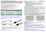
New Ny-Trex Products
1
Ny-Trex Progressive Nitrous Controller
offers a diverse list of functions which allow
control of up to two stages of N2O. Built-in
data logging capabilities and computer
software will assist in analysis and tuning of
any N2O system for maximum performance.
Equipped with both programmable window
switches and inputs/outputs put it one step
in front of the competition. Logs throttle
position, RPM, vehicle speed, status of all
inputs and outputs, and two 0-5V analog
inputs. Comes complete with
software and USB cable
for quick installation.
PART# 160030
OWNER’S MANUAL
Ny-Trex Accu-Pressure Bottle Heater
with a mirror-like polished finish features a
unique heating element capable of heating a
bottle in half the time of traditional silicone
blanket style heaters. The temperature is
controlled by an adjustable pressure switch
while most others use a less accurate
temperature switch.
PART# 120040
CONGRATULATIONS
ON THE PURCHASE OF YOUR NY-TREX NITROUS OXIDE
PERFORMANCE SYSTEM
NOTICE: Installation of Ny-Trex performance products signifies that
you have read this entire document and all warnings and agree to all
the terms stated within.
Ny-Trex assumes no responsibility for damages or injury occurring
from accident, misuse, abuse, improper installation, improper
operation, lack of reasonable care and handling, or all subsequently
stated reasons resulting from incompatibility with other
manufacturer’s products.
Do not use or operate this or any other Ny-Trex product on
public roads or highways. Ny-Trex neither recommends or
condones the use of products manufactured or sold by Ny-Trex on
vehicles, which may be driven on public roads or highways, and
assumes no responsibility for damages or injury incurred by such
use.
Ny-Trex assumes no responsibility or liability for damages or injury
incurred by the use of products manufactured or sold by Ny-Trex on
vehicles used for competition or racing.
It is the purchaser’s and installer’s responsibility to follow all
instructions, guidelines, warnings, and safety procedures supplied
with the product as it is received by the purchaser or installer, and
to determine the compatibility of the product with the vehicle or the
device the product is to be installed.
www.Ny-Trex.com
7ROOIUHH
)D[
6DOHV#'HVLJQ(QJLQHHULQJFRP
rev. 20120614
19
2
Safety Tips
Read and carefully follow all warnings, cautions, safety tips and
instructions before Installing or using any Ny-Trex products.
Ny-Trex system components are made of top quality materials and are
designed with the highest regard for safety. If you have any questions
regarding the performance or safety of your system, call Ny-Trex Technical
Service at: 1-800-264-9472.
While nitrous oxide is legal for use in most states when used in accordance
with state and local traffic laws and sanctioned racing rules and guidelines,
Ny-Trex does not recommend or condone the use of its products on
any public roads, highways or in any illegal racing activity.
Ny-Trex has not pursued California Air Research Board (CARB) exemptions for
these kits; hence, they are not legal for use on pollution-controlled vehicles in
California. A correctly installed Ny-Trex Nitrous Oxide Performance System
should not alter the emission control performance of your vehicle, under
standard EPA test cycle conditions.
CAUTION! The Ny-Trex Universal 4 & 6 Cylinder Nitrous Oxide Performance
Kits are not intended for use on hatchback type vehicles without the use of an
External Aluminum Blow-Down Tube and Racer Safety Pressure Relief Cap.
Other Ny-Trex Products
Ny-Trex PURGE Kit
Everything you need to purge.
Tubing, fittings, brackets, mounting
hardware, switch, and connectors.
Ny-Trex 10 Lb. High-Flo Bottle
Powder-coated “Wet Black” with
chrome CGA 660 High-Flo valve.
Billet Aluminum Bottle Brackets
Single or Dual quick-release with
carry handle.
Liquid-Filled Bottle Gauge
Custom Liquid filled, 0-1500 PSI
high pressure gauge.
Stainless Braided Lines
Teflon inner core, all sizes
2” to 18’ long.
HAZARDS DEFINED
This manual provides step-by-step instructions that describe the process of
installing your Ny-Trex Nitrous Oxide Performance System. These procedures
provide a framework for installation and operation of this kit. All parts within
this installation kit, are referenced by name and number(#) to avoid confusion
during installation.
Within the instructions, you are advised of potential hazards, pitfalls, and
problems to avoid. The following examples explain the various hazard levels:
T-Rex Hi-Flo Wet Nozzle
Flows up to 300 HP.
Fuel Pressure Safety Switch
Prevents engine damage due to
low fuel pressure.
WARNING! Failure to comply with instructions may result in injury or
death.
CAUTION!
Failure to comply with instructions may result in damage to
equipment.
NOTE: This information is important, needs to be emphasized, and is set
apart from the rest of the text.
HINT: These special instructions provide a handy work tip.
Stainless Hi-Flo Solenoids
175 HP “Hot-Shot”
300 HP “Phat-Shot”
450+ HP “Split-Shot”
Ny-Trex Trans-Fill System
Complete with pump, digital scale,
tray, braided stainless lines, and filter.
To Order: By Phone: 800-264-9472
By Web: Ny-Trex.com
rev. 20120614
18
3
Safety Tips
Be Cool, Don’t Drink and Drive
“It will only slow you down”
Read and carefully follow all warnings, cautions, safety tips and
instructions before installing or using any Ny-Trex product.
NOTES:
WARNINGS!
1. Do not attempt to start the engine if the nitrous has been injected while
the engine was not running. Disconnect the coil wire and turn the engine
over with the throttle wide open for several revolutions before attempting
to start. Failure to do so can result in extreme engine damage.
2.
Never permit oil, grease, or any other readily combustible substances to
come in contact with cylinders, valves, solenoids, hoses, and fittings. Oil
and certain gases (such as oxygen and nitrous oxide) may combine to
produce a highly flammable condition.
3.
Never interchange nitrous and fuel solenoids. Failure to follow these
simple instructions can result in extreme engine damage and/or personal
injury.
4.
Never drop or violently strike the bottle. Doing so may result in an
explosive bottle failure.
5.
Never change pressure settings of safety relief valve on the nitrous bottle
valve. Increasing the safety relief valve pressure settings may create an
explosive bottle hazard.
6. Identify the gas content by the label on any bottle before using. If the
bottle is not identified to show the gas contained, return the bottle to the
supplier.
7.
Do not alter or remove any markings on the nitrous bottle.
8. Nitrous bottle valves should always be closed when the system is not
being used.
9. Notify the supplier of any condition, which might have permitted any
foreign matter to enter the valve or bottle.
10. Keep the valves closed on all empty bottles to prevent accidental
contamination.
11. After storage, momentarily open the nitrous bottle valve to clear the
opening of any possible dust or dirt.
12. It is important that all threads on the valves and solenoids are properly
mated. Never force connections that do not fit properly.
13. Never use an open flame to heat a nitrous bottle. Explosive bottle
failure could occur and cause serious injury or death.
rev. 20120614
4
17
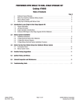
Table Of Contents
Troubleshooting Guide
Safety Tips...…………………………………………………………..2
Problem
Possible Cause
Diagnose Problem
Table of Contents…………………………………………………….4
No change in
performance when
system is activated
Malfunctioning
arming switch
Turn arming switch to
Replace arming
“ON” position. Connect switch
12v test light to ground
and check for power on
both terminals of switch.
Connect 12v test light to Repair wiring
ground. Check for power
at “Keyed 12v” terminal.
Tools Needed………………………………………………………….5
Introduction.……………………………………………….………… 6
No power to
arming switch
Jetting Chart …………………………………………………………6.A
Loose Ground wire Connect 12v test light to Tighten/repair any
battery(+). Check for
loose grounds
continuity at all grounds
(Fig. 14.A).
Before You Begin.……………………………………………………7
System Overview ..………………………………………………….8
System wired
incorrectly
Component Overview .……………………………………………..9
Malfunctioning
WOT switch
Bottle Mounting & Feed Line Installation…………..………10
Bottle Illustration..……………………………………………….10.A
Nozzle & Solenoid Mounting Instructions.………………...11
Overly rich fuel
condition
Nozzle Mounting Illustration .……………………………….11.A
Fuel Supply Connections ….……………………………………..12
Fuel Rail Illustration…..………………………………………..12.A
Engine detonates
heavily when system
activated
Electrical Hook-Up....………………………………..…………….14
Wiring Diagram …………………………………………………..14.A
Compare all wiring and
connections to that on
Fig. 14.A.
Disconnect "red" power
relay wire from WOT
switch. Connect 12v test
light to ground, turn on
arming switch. Manually
activate WOT switch.
Check for continuity at
WOT switch terminal.
Replace WOT
switch
Check fuel pressure
Repair/replace fuel
gauge while engine is
pump
running under load and
wide-open throttle. Fuel
pressure should be within
5psi of idle pressure.
Replace plugs/set
gap at .030" to
035"
Weak ignition or
Inspect all components,
ignition component plug wires, distributor
failure
cap, etc.
Surges under
acceleration when
system activated
Wire systems per
instructions
Check for black smoke or Install smaller fuel
back-firing through
jet or decrease
exhaust.
fuel pressure
Inspect filter and line.
Clean filter or
replace line
High RPM misfire when Bad spark plugs or Inspect spark plugs.
system activated
improper gap
Other Ny-Trex Products ……...…………………………………..18
Be Cool, Don’t Drink and Drive.………………………………...19
Not enough fuel.
Clogged filter or
crimped line
Weak fuel pump
Banjo Fitting Illustration…………………………………..….12.B
Troubleshooting Guide ……………………………………………16
Correct Problem
Replace worn or
faulty components
Inadequate supply Check bottle weight
Replace or fill
of nitrous
(24 lbs. 12 oz. Full; 14 lbs. nitrous bottle
12 oz. Empty).
Bottle mounted
Check bottle orientation Mount bottle
incorrectly
(Fig. 10.A).
properly
rev. 20120614
16
5
Tools Needed
Troubleshooting Guide
Problem
Possible Cause
Do Yourself a Favor and Round Up These Tools
Before You Begin the Installation
Diagnose Problem
Correct Problem
Engine speed changes Faulty nitrous
when opening or closing solenoid
bottle valve
Remove, clean and
inspect solenoid.
Disassemble,
clean, repair or
replace solenoid
Engine runs rich when
system is activated
Bottle valve not
open
Check bottle valve.
Open valve fully
Bottle mounted
Improperly
Check bottle orientation Mount bottle
(Fig. 10.A).
properly
Plugged nitrous
line or nitrous jet
Inspect lines and jets.
Clean debris or
replace
Low bottle
pressure
Check bottle temperature.
Keep bottle temp
at 75-85°F
PURPOSE
TOOL
CHECK
1
10" Crescent Wrench
Tighten Bottle Nut
2
3/8” Box End Wrench
Tighten Nozzle Hose Fitting
3
Tighten Nozzle Hose End
4
7/16" Box End Wrench
1/2" Box End Wrench
5
9/16" Box End Wrench
Tighten Fuel Supply Line
6
Flat Blade Screwdriver
Tighten Hose Clamps
7
#1 Phillips Screwdriver
Install WOT Snap Switch/ Toggle
Insufficient nitrous Weigh bottle (24 lbs.12oz. Fill bottle
supply
Full, 14 lbs.12 oz. empty).
8
#2 Phillips Screwdriver
Install Solenoids to Mounting
9
1/4" Nut Driver
Tighten Nut on WOT Snap Switch
Mismatched N2O/
fuel jetting
Compare jetting to jet
chart (Fig. 6.A).
10
3/16" Drill Bit
Drill Pilot Holes For Brackets
11
1/2" Drill Bit
Drill Holes For Well Nuts
Excessive fuel
pressure
Check pressure with fuel Regulate pressure
pressure gauge during
down, or install
acceleration with system smaller fuel jetting
activated.
12
9/16" Drill Bit
Drill Hole For Nozzle Fitting Adapt-
13
3/8" Drive Ratchet
Install Brackets
14
7/16" Socket / Wrench
Install Solenoid Mounting Bracket
15
3/8" Socket / Wrench
Install Bottle Bracket Bolts
16
Wire Strippers
Strip and Cut Wiring
17
Wire Crimpers
Crimp Butt / Terminal Connectors
18
Dyke Pliers
Cut Wire & Tie Wraps
19
Battery or Electric Drill
Drill Holes
20
Needle Nose Pliers
Bend WOT Switch Tab
21
Shop Towels
Absorb Fuel Spillage
22
Tap Handle
Tap 1/16” NPT for Fuel Connection
Install correct jets
Loose nitrous
solenoid wiring
Inspect solenoid wiring.
Malfunctioning
nitrous solenoid
Turn off engine. Discon- Rebuild or replace
nect nitrous outlet line. solenoid
With bottle open, activate
nitrous solenoid. Nitrous
should discharge at high
rate. WARNING! Do not
inhale nitrous or allow
skin contact. Frostbite,
serious injury or death
could occur.
Engine detonates mildly Excessive ignition Check ignition timing
when system is
timing
activated
Inadequate octane
fuel
Spark plug heat
range to high
Too much nitrous
flow
Repair wiring
Reduce ignition
timing in 2 degree
increments
Use higher octane
fuel
Reduce spark plug
heat range (max. 2
steps)
Reduce nitrous
jetting
Tighten Nitrous Supply Line
NOTE: You will also need other tools based on your particular vehicle.
Common tools include metric wrenches and sockets. Also, you may need a
floor jack and stands to insure safe access to the under-side of the vehicle.
rev. 20120614
6
Introduction
General Information
This system is designed to be used on both late model EFI and early model
carburetor systems with stock fuel pumps. For those that have an aftermarket
ECU or ignition that advances timing, detonation could become a problem.
However, these ECUs may still be used by retarding timing 1-1.5 degrees per
50HP increase or using a higher octane fuel.
NOTE: Specific application numbers have the appropriate base jetting for
either EFI(@45psi) or low pressure carbureted systems (@6.5psi).
CAUTION! It is the responsibility of the Purchaser or Installer to insure
proper jetting and tuning for safe and reliable operation. Continued detonation will cause severe engine damage. When tuning your nitrous system
above the recommended 75 HP increase, or adding dual stage nitrous, a high
capacity aftermarket fuel pump must be installed and timing retarded (2 to 4
degrees).
System Requirements
Ny-Trex kits are designed for safety and smoothness of operation. When used
correctly, these kits will work with stock internal engine components.
To ensure proper performance and engine life, the following
requirements must be satisfied:
Manual Transmissions If the vehicle is exposed to severe operating conditions, such as drag strip use, the standard clutch should be replaced with
a high-performance unit.
Automatic Transmissions If the vehicle is exposed to severe operating
conditions, such as drag strip use, a reputable high-performance transmission shop should service the transmission.
Nitrous oxide is injected only when the following conditions are met:
1. Bottle Valve is Open
2. System is Armed
3. Engine is at Wide-Open Throttle
Drivability, fuel economy, and exhaust emissions should not be affected
under normal part-throttle conditions.
FIGURE 6.A
Baseline Jetting Chart
Electrical Hook-Up
15
3. The Activation Arm is the extra long metal lever on the WOT switch.
This allows you to twist, bend, shape or cut it to aid in the ease of installation. Use needle nose pliers to form a suitable shape and position. Adjust
the position to insure the WOT switch “clicks” at the same point the throttle
linkage reaches wide-open throttle against the throttle stop.
HINT: Try to bend loops or double over before cutting the metal lever. This
will add strength and allow for future adjustments.
4. Attach an 18-gauge Jumper Wire using “Red” wire and spade
connectors provided (29). Attach from remaining terminal on Arming switch
(25) to either of the terminals on the WOT switch.
NOTE: Test the WOT switch action. Check for binding or anything that may
impede the throttle action. Zip tie wire away from any cables or linkage.
CAUTION! Improperly mounted WOT switch can cause throttle to hang and
create a dangerous “stuck-throttle” condition. Ensure that the WOT switch
does not interfere with normal throttle linkage operation.
Relay Installation
1. Mount Relay (26) on firewall or location within reach of components.
1. Mount Relay RQ¿UHZDOORUORFDWLRQZLWKLQUHDFKRIFRPSRQHQWV
2.Connect
Connect
Relay
Using “Red” 18-gauge wire supplied with the system,
2.
to To
Relay
8VLQJ³5HG´JDXJHZLUHVXSSOLHGZLWKWKHV\VWHPFRQQHFWWKH
connect the remaining wide-open throttle terminal to the “Black” wire on
UHPDLQLQJZLGHRSHQWKURWWOHWHUPLQDOWRWKHWHUPLQDORQWKHVXSSOLHGKHDY\GXW\UHOD\
the supplied relay plug (26). (See wiring diagram Fig. 14.A)
SOXJ6HHZLULQJGLDJUDP)LJ$
3. Power The Relay Connect “Black” 14 gauge wire supplied, to the “BAT”
3. Power
the Relay
terminal
of the&RQQHFW³%ODFN´JDXJHZLUHVXSSOLHGWRWKH³%$7´WHUPLQDORIWKH
alternator or the positive (+) terminal of the battery,
DOWHUQDWRURUWKHSRVLWLYHWHUPLQDORIWKHEDWWHU\WKHQFRQQHFWWRWKHWHUPLQDORQWKH
then connect it to the “Yellow” wire on the relay plug (26). (If desired a
KHDY\GXW\UHOD\SOXJ,IGHVLUHGDDPSIXVHPD\EHLQVWDOOHGKHUH
40 amp fuse may be installed here).
4.
theThe
Solenoids$WWDFKERWK³5HGDQG%OXH´ZLUHIURPHDFKRIWKHVROHQRLGVWR
4.Connect
Connect
Solenoids Attach both “Red & Blue” wire from each of the
WKHWHUPLQDORQWKHUHOD\SOXJ$WWDFKWKHWZRUHPDLQLQJ³%ODFN´VROHQRLGZLUHVWR
solenoids to the “Blue” wire on the relay plug (26). Attach the two remaining “Black” solenoid wires to a good ground. The solenoid coils have
DJRRGJURXQG7KHVROHQRLGFRLOVKDYHGLRGHV&DUHIXOO\REVHUYHSRODULW\5HG%OXH
diodes, carefully observe polarity (Red, Blue +) (Black to ground).
%ODFNWRJURXQG
Ground
Relay Attach “White” wire from relay plug to fuel pressure
5.
5. Ground
theThe
Relay$WWDFKWHUPLQDOIURPUHOD\WRIXHOSUHVVXUHVDIHW\VZLWFKWHU
safety switch (31) terminal marked (NO). Using 18 gauge White wire,
PLQDOPDUNHG128VLQJJDXJHZKLWHZLUHDWWDFKWKHWHUPLQDORQIXHOSUHVVXUHVDIHW\
attach the terminal on fuel pressure safety switch marked (C) to ground.
VZLWFKPDUNHG&WRJURXQG)LJ$
(Fig. 14.A)
NOTE: If fuel pressure switch is not used, simply attach the “White” wire on
the relay Plug (26) to ground.
Connect Battery Cable
2. Test Solenoids for proper operation. Be sure the nitrous bottle valve is
NOTE: Baseline calculations at 900 psi bottle pressure, N2O-to-Fuel ratio at 5.5:1,
fuel specific gravity of .740. Baseline jetting targets 11:1 air-to-fuel ratio. (Results
may vary upon engine type). It is recommended to start with the lowest HP increase to
test the system and compatibility. Move up in HP only after you are confident your
components are capable of the increase and you have checked the system for any leaks
or potential hazards.
OFF and no pressure is in the supply line. If using a fuel safety switch,
you must use a jumper wire between the NO and C terminals while
testing the solenoids. To test, turn the Arming Switch ON, and push the
“activating” WOT switch. A click will be heard when the solenoids open.
3. CAUTION! Make sure that both of the solenoids are clicking! If no sound
is heard or only one solenoid is working, check wire connections and
refer to the wiring schematic ( Fig. 14.A) for proper connections.
4. Check All Components With feed lines and electrical connections
completed and nitrous supply line connected to the bottle, FULLY open
the bottle valve and carefully check connections on the nitrous side of
the system for leaks. Re-tighten fittings if necessary. With no leaks
detected, start engine and thoroughly check fuel connections for leaks.
5. Have Fun and Be Safe Remember to always obey all your state and
local motor vehicles laws and regulations. Only race in sanctioned racing
venues and events that have proper safety equipment and adequate
medical facilities. Never use Ny-Trex or any nitrous oxide equipment on
public roads or highways.
rev. 20120614
14
Electrical Hook-Up
7
Before You Begin
Arming Switch Installation
1. Disconnect The Battery
2. Mount The Arming Switch (25) in a location that is within easy reach
and in plain sight of the driver.
3. Connect 12v Lead Using 18-gauge “Red” wire and connectors provided
(29), connect “12v DC Positive” from the fuse panel to one terminal of
the Arming switch. (Use a 5 amp in line fuse if desired). This power
source must be fused and controlled by the ignition.
Wiring Diagram
ALWAYS
Read all instructions before you
begin installing your Ny-Trex Nitrous Oxide Performance System.
Never begin installing or using any
Ny-Trex products without carefully
reading all safety tips and warnings.
Check your fuel system for adequate pressure and flow for the jets
you have chosen.
Never operate your nitrous system
with inadequate fuel flow as serious
engine damage will occur.
Use a minimum of 14 gauge wire
and high quality connections when
installing electrical components.
Never use improper wire such as
speaker wire, bare wire, solid wire,
or any wire not approved for automotive use.
Use Teflon based paste on NPT pipe
style fittings. Check for leaks at all
nitrous and fuel connections.
Never use sealer on AN flare style
fitting. Never use thread tape on any
fittings.
Make sure that your engine and all
related components are in safe and
proper working condition.
Never install or operate nitrous
system with inadequate ignition
components, fuel system , brakes
or driveline.
Use nitrous system above 3000 RPM
or at Wide-Open-Throttle only. Failure to do so could result in explosion and severe damage to engine.
Never start engine when nitrous has
been injected accidentally without
engine running. Turn off nitrous,
disconnect coil and crank engine for
10-15 sec. before starting engine.
Check and install proper engine to
chassis ground. Failure to do so
could cause explosion of main
nitrous supply line.
Never allow nitrous line to come in
contact with hot engine, exhaust,
electric current, or any ignition
components. Explosion could occur.
Use high-quality fuel and suggested
jetting combinations. Clean up any
spilled fuel before starting engine.
Never allow nitrous bottle to exceed
1100 PSI. Never use methanol
based fuel or octane booster.
Only use a CGA approved nitrous
oxide filling station. Firmly secure
nitrous bottle when transporting.
Never breathe nitrous oxide.
Never let nitrous contact skin.
Death due to suffocation or
frostbite could occur.
Thoroughly check for fuel leaks after installation .
Never heat the nitrous bottle with an
open flame. Explosion and serious
injury or death could occur.
FIGURE 14.A
WOT Switch Installation
1. The Wide Open Throttle Switch Is a universal micro-switch designed to
work with the universal mounting bracket (17). The capacity is 10 amps
and should only be used to activate low amp draw accessories in conjunction with the relay (26).
2. Mount The WOT Switch using bracket (17) with 3/4” 4-40 screws and
nuts. By flipping the bracket and switch, the switch can be mounted in a
variety of different configurations. Select the most suitable position and
tighten the screws. (Do not over-tighten the screws, the plastic microswitch can be damaged).
NOTE: The Mounting Bracket (17) is made of easily bendable material and
may be formed to any configuration that will allow placement of the WOT
switch in the proper location. (While typical location of WOT switch mounting
is at throttle valve located on the engine, some may find it more accessible
to mount under dash at the gas peddle linkage).
NEVER
rev. 20120614
13
8
Fuel Supply Connections
System Overview
The following illustration shows the individual Ny-Trex nitrous components and their relationship. Take a moment to familiarize yourself with
each part by using the reference number and the component list on the
following page (Fig. 9.A).
These reference numbers will be used thru out the manual to help you
identify the components during installation.
HINT: To speed installation time, after unpacking place components in
the same arrangement as shown in Fig. 9.A. This will allow you to
identify and reference the components as you work thru the step by
step installation process.
(1)
FIGURE 8.A
NOTE: After determining the most suitable fuel connection, make certain that
the fuel system has adequate flow and pressure, and that you are tapping
into the high pressure line, not the return line.
HINT: Refer to vehicle service manual or consult qualified technician.
WARNING! The fuel rail and fuel lines are under high pressure! Use
extreme caution when disconnecting any fuel line. Do not open fuel ports or
lines while the engine is hot. Quickly collect and properly dispose any fuel
spillage. Certain vehicles have hard plastic fuel lines with a rubber-like shell,
Do Not cut or splice this type of line as leak proof seal cannot be assured.
Failure to comply could cause engine damage, injury, or death.
1. High Pressure Fuel Line Connection. (Rubber Hose Only!)
Locate the high pressure fuel line (not return line) and choose a location
between the fuel filter and the EFI fuel rail. Using caution, cut the hose and
install the barbed fuel tee (7) and supplied clamps (5). Tighten clamps securely. Absorb any spilled gas with shop rag.
2. Factory Fuel Test-Port Connection.
(8)
(5,6)
Figure 12.A Located on the Fuel Injector Rail is a “test-port” fitting used by
technicians to check fuel pressure. This port is usually covered with a
protective plastic cap. Remove the protective cap from the test-port. Observing caution and shop rags to absorb any spilled gas, use a valve stem core
remover or needle nose pliers to remove the Schrader Valve from the connector fitting. Install fuel supply line (4).
NOTE: Most Fords and some imports will require the entire test-port to be
removed and replaced with the supplied 1/16 x-4 fitting (14). Be sure to
check the compatibility of the fitting on the fuel line.
(14)
NOTE: Many late model vehicles have similar ports that do not give access to
(3)
(2)
(4)
(19)
fuel.
(19)
3. Fuel Rail or Banjo Fitting Connection.
AIL
FUEL R
(17)
(17)
(11)
(11)
(16)
(16)
(23)
(20)
AIR FLOW
(20)
AIR INLET DUCT
Figure 12.A & B Locate the high pressure fuel line that connects to the fuel
rail or distribution block. Determine the most suitable type of connection,
either tapping into banjo fitting, or tapping into fuel rail.
To Tap Banjo Fitting (Fig. 12.B) Observing caution and shop rags to absorb any excess spilled gas, remove fuel line. Place Banjo bolt securely in
vise. Mark and center punch the Banjo bolt head. Drill a small pilot hole, then
follow up with the 1/4” drill supplied (13). Tap hole with 1/16 NPT tap supplied (15). Install 1/16x-4 fitting (14).
To Tap Fuel Rail (Fig. 12.A) Observing caution and shop rags to absorb
any excess spilled gas, remove the fuel rail. Remove all injectors, regulators,
and fittings that may trap debris. Clamp fuel rail securely in vise, mark and
center punch the most suitable location (must have enough wall thickness to
achieve 3 to 4 threads of engagement). Drill small pilot hole, then follow up
with 1/4” drill supplied (13), tap hole with 1/16 NPT tap supplied (15).
Install 1/16x-4 NPT fitting (14).
CAUTION! All debris must be removed from fuel rail and fittings. Failure to
do so could cause injector failure and engine damage. Check for fuel leaks
before starting engine.
NOTE: Use of compressed air is an effective cleaning method. Use Teflon
thread sealer (12) on all NPT pipe threads. Never use thread tape!
Replace all parts in reverse order and check for leaks.
rev. 20120614
9
12
Fuel Supply Connections
Determine Type of Connection
There are 3 possible ways to tap into the factory fuel system.
1. Splicing into the rubber high pressure fuel line and installing fuel tee (not
shown).
2. Tapping into factory fuel “Test-Port” (Fig. 12.A).
3. Drill and tap Fuel Rail or Banjo fitting and installing 1/16x-4 fitting (Fig.
12.B).
FIGURE 12.A
FITTINGS HAVE BOTH
“NPT” PIPE THREADS
AND “AN” STYLE
FLARE ENDS
“AN” FLARE
USE NO
SEALER
TEST PORT
FUEL RAIL
FUEL INJECTION
NOZZLE
“NPT” PIPE
USE PASTE
SEALER
PLENUM
FIGURE 12.B
IF FUEL SUPPLY HOSE
FITTING IS NOT
COMPATIBLE WITH
TEST PORT THREADS,
REMOVE THE PORT
AND REPLACE WITH
1/16 x-4 FITTING (14)
FROM FUEL TANK
LOCATE MAIN FUEL
SUPPLY, DRILL, TAP,
INSTALL 1/16 NPT x-4
(14) IN BANJO FITTING
BOLT AT EITHER
LOCATION.
FUEL FLOW
FUEL
FILTER
AFTER
BEFORE
1/16 x-4 FITTING
(14)
TO FUEL RAIL OR
FUEL DISTRIBUTION
BLOCK
rev. 20120614
10
11
Bottle and Feed Line Installation
Nozzle & Solenoid Mounting
Bottle Installation
1. Determine Mounting Location Identify air inlet duct located between
throttle body and mass air flow sensor, air filter, or cold air inlet. Choose
suitable location between 2” to 12” from throttle body inlet. Mark location.
NOTE: Exact location is not crucial, however, avoid any sharp bends or
obstructions. Choose location that will accommodate the solenoids and
injector lines without putting tension on the lines or nozzle.
2. Remove Air Inlet Duct located between throttle body and air filter.
3. Rubber or Hard Plastic Drill or cut 9/16” hole in the chosen location and
install nozzle adapter (20) from inside of duct and adapter nut (20) to outside.
4. Metal Mounting Surface If mounting material is thick enough for adequate thread engagement (3 threads or more), drill with a 21/64” bit and
tap with a 1/8 NPT pipe tap. Install nozzle without adapter. For thinner
material use same procedure as rubber or hard plastic (above).
NOTE: Clean all debris from duct before replacing. Use a silicone type
sealer around nozzle adapter to prevent leaks. Make sure spray nozzle is
facing throttle body. (Fig. 11.A)
5. Install N-T Nitrous Nozzle (23) Mount nozzle with spray pattern facing
toward throttle body. Install fuel jet(16) & Red fuel line (11) to nozzle
fitting nearest throttle body. Install nitrous jet(16) and Blue nitrous line
(11).
Nozzle Mounting
1. Insert Nylon Washer (9) into bottle nut (4) and securely tighten onto the
bottle valve.
2. Mount Bottle Brackets (2) to Bottle (1). Position label and gauge port
facing up and mounting brackets down. Place on level surface and tighten
clamps at proper position. You are now ready to trial fit bottle in place.
3. Locate Mounting Area using the bottle unit as a pattern. Locate a suitable mounting area in the trunk that will provide for easy access to bottle
valve, hose connection, and bottle removal.
NOTE: Longer wheelbase vehicles should consider routing nitrous feed line
(3) first to assure adequate length before permanently mounting bottle.
4. Mark and Drill Holes Check area below for obstructions such as gas tank or
wiring, then drill pilot holes with 3/16” drill bit followed by 1/2” bit.
5. Insert Well Nuts (10) into holes, check alignment with bottle unit.
NOTE: Well Nuts are the Black rubber inserts provided (10) and are to be
used when there is no access from the bottom of vehicle. If full access to
underside is available, use 3/8 bolts, nuts and washers (not included).
6. Install Bottle with 1/4 x 20 shoulder bolts (10) and tighten securely. Be
careful not to over tighten. Test by rocking side to side. Bottle should stay
firmly in place.
NOTE: It is important to have the label and gauge port facing up and
the tank valve facing forward to insure that the internal siphon tube will
pick up liquid nitrous. (Fig. 10.A)
Bottle Mounting Instructions
FIGURE 10.A
Label Facing Up
FUEL
LINE
NITROUS
LINE
Gauge Port Up
FIGURE 11.A
FUEL
JET
“SPRAY”
PATTERN
TOWARD
THROTTLE
NITROUS JET
N-T
NOZZLE
Siphon
Tube
Front of Vehicle
Routing the Nitrous Feed Line
1. Determine The Best Routing Path from the engine compartment to the
trunk, either through the passenger compartment or the underside of the
vehicle.
NOTE: Longer wheel base vehicles need to consider the shortest routing
path to assure adequate hose length. Look for short-cuts such as routing
under carpets, factory holes under rear seat, behind body panels, etc.
CAUTION! Do not route nitrous feed line(3) near exhaust, any hot surface, or moving suspension component. Whenever possible, route behind any heat shield or protective panels.
2. To prevent flow restrictions, route the feed line(3) carefully. If routed
under the vehicle, locate and drill a hole near the bottle valve for nitrous
feed line, or use factory access plug if possible.
3. Route the Feed Line (3) to engine compartment. Following the factory
fuel line is usually a good path. Use zip ties (28) to secure the feed line,
taking care to keep away from any hot wire or any hazard such as hot
exhaust, driveline, or moving suspension components.
HINT: Cover line ends with tape to prevent debris from entering feed line
during the routing process.
Solenoid Mounting
1. Install solenoid fittings (where applicable) Secure solenoids in vise or with
pliers to prevent turning, install 1/8 x-4 fitting to the “IN” port and the 1/8
x-3 to the “OUT” port using thread sealer provided and tighten with wrench.
HINT: Place shop rag in vise or pliers to prevent scratching valve body.
CAUTION! Do not clamp coil part of solenoid valve. Damage could occur.
2. Determine Mounting Location With the two 20” braided lines (11) attached
to the N-T nozzle (23), search for a suitable location within reach of lines
observing orientation of fittings and lines. The firewall, side panel, or factory
brackets are usually good mounting points.
3. Mount Solenoids to Brackets By flipping brackets, there are 4 possible
mounting positions (2 per side, w/a). Determine best position, (consider the
location of “IN”&“OUT” to lines/nozzle) and mount with supplied screws.
4. Mount Solenoids Bend brackets (17) into suitable mounting position and
mount solenoids (close to each other, w/a) using supplied mounting screws
(10), or factory bolt at selected location. Attach fuel and nitrous lines to solenoids and tighten securely. (Do not use sealer or tape on AN line fittings).
CAUTION! Avoid any obstructions that may come in contact with solenoids
or lines such as the hood, throttle cables, etc. Keep lines and hoses clear of
engine, exhaust, or any hot surface. Check for leaks before starting engine.
rev. 20120614