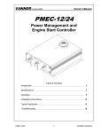
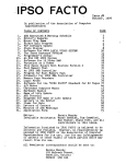
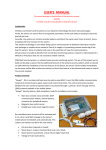
1
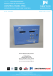
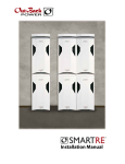
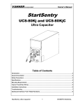
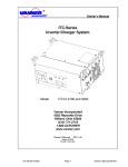
VANNER Incorporated Owner’s Manual PMECM-12/24 idleWATCH® II Power Management and Engine Start Controller PMECM-12/24 1 OWNER’S MANUAL VANNER Incorporated Owner's Manual Table of Contents Introduction and General Description.…………………….………………… 3 Specifications…………………………………………………….………….… 4 Theory of Operation……………..……………………………………………. 5 Installation Instructions…………………………...…………….……………. 15 Typical Application/Wiring………………….………...……………………… 20 Troubleshooting………………………………………………………………. 23 PMECM-12/24 2 OWNER’S MANUAL VANNER Incorporated Owner's Manual Introduction Thank you for purchasing Vanner’s PMECM-12/24 Power Management and Engine Start Controller, commonly referred to as idleWATCH®II. The idleWATCH®II is an idle reduction system that helps fleets meet the industry’s no-idle regulations in addition to reducing fuel consumption and exhaust emissions. We are confident that you will be pleased with its performance because Vanner products are designed and manufactured by skilled professionals using the highest standards in workmanship. With minimum maintenance and care, you can be assured of many years of trouble free service. General Description The Vanner idleWATCH®II constantly monitors the state of charge (SOC) and state of health (SOH) of a vehicle’s auxiliary batteries. When the idleWATCH®II Auto Start functionality is enabled, the engine will start automatically to recharge the batteries when they reach a user defined state of charge (SOC). This enables a worker to run 12V or 24V loads during the workday, while in park and the engine off, without the worry of discharging the batteries. When the auxiliary batteries are discharged to a user configurable “Engine On” state of charge, the idleWATCH®II sends a signal to a remote starter* to start the engine and recharge the batteries. Fast idle mode* will be employed during the recharge cycle if it is necessary. Once the battery’s “Engine Off” state of charge is achieved, the idleWATCH®II will automatically turn the engine off. The idleWATCH®II is also provisioned with fuel saving idle shutdown functionality in the event the vehicle is key started while in park. The duration of idle time is user configurable via Vanner's Dashboard Interface software. The idleWATCH®II is J1939 CAN (Controller Area Network) enabled and is fully configurable over a J1939 compliant network via laptop. (Reference the Vanner CAN Interface User Manual for configuration instructions.) A typical idleWATCH®II system consists of the following; 1) PMECM-12/24 a) Main power and control circuitry housed in a sealed plastic enclosure b) Four, 12 position Deutsch connectors for sensor and vehicle I/O plus CAN communication 2) Panel or Dash Mounted Remote a) Enables and disables the idleWATCH®II system b) LED status indicators c) Audible buzzer for engine shutdown warning (30 seconds prior to engine shutdown) 3) Current Sensor (VSS-C80/600 or VSS-C80) a) Toroid style current sensor b) One or more current sensors may be required depending on system configuration 4) Battery Voltage and Temperature Sensor (VSS-VT) a) Stud mounted sensor for monitoring battery voltage and temperature 5) Custom Fortin Remote Start Module (Optional) a) The custom, application specific Fortin Remote Start Module must be purchased through Vanner. 6) In certain applications, an additional Fortin module is required for Security Key bypass capabilities, this module is configured on the vehicle. * Note: The idleWATCH®II is provisioned with the capability of starting the vehicle without the use of a remote start module. Engine crank time, crank interval, crank attempts and cranking delay are all user configurable via a laptop provisioned with Vanner's Dashboard Interface. PMECM-12/24 3 OWNER’S MANUAL VANNER Incorporated Owner's Manual Specifications PMECM-12/24 Power Management and Engine Start Controller Model Number Input Voltage Range (VDC) PMECM-12/24 9.5 – 32 (Reverse Polarity Protected) Max Input Current (AMPS) Output Voltage Range (VDC) Max Ripple Voltage (mV) Standby Current (Milliamps) Operating Temp. Storage Temp. Serviceable 15 9.5 - 32 <100mV RMS <30mA @ 24V, <60mA @ 12V -40°C to +60°C (-40°F to 140°F) -40°C to +85°C (-40°F to 185°F) Internal components to be serviced by Vanner personnel only. Environmental Considerations Sealed plastic enclosure (Nylon 6/6) provides protection against salt, fungus, dust, water, fuel vapors and all fluids associated with commercial and off-highway vehicle operations. IP67 Rated. Mounting Location Weight (lbs.) Mount on a flat surface. Location should be protected from battery acid and gases. 1.25 lbs (.6 kG) Dimensional Specifications (All Dimensions are in Inches) PMECM-12/24 4 OWNER’S MANUAL VANNER Incorporated OWNER’S MANUAL Theory of Operation Battery Monitoring The primary function of the idleWATCH®II is to monitor and manage the auxiliary batteries on a vehicle. The monitoring algorithm analyzes battery voltage, current, and temperature inputs, and calculates the SOC (State of Charge), SOH (State of Health), SOCach (Achievable State of Charge based on SOH and temperature of battery), U (Estimated Time to Run), and Up (Estimated Time to Run adjusted by SOH and temperature of battery) of the battery. In order for the idleWATCH®II system to accurately calculate/estimate the SOC, SOH and SOCach, of the battery/batteries, there are three critical settings that need to be configured. The settings are as follows; Battery Type: This is defined by the make and model of the battery being used. Nb: This is the number of batteries that are connected in parallel Voltage Level: The voltage level setting defines whether it is a 12V single, 24V single or 24/12V dual battery arrangement An idleWATCH®II is ordered from the factory with the customer defined battery profile, Nb and voltage level settings pre-loaded. Please review Vanner's smart part numbering document, A916580, to ensure you specify the appropriate model number for the application. Alternatively, the appropriate battery profile, Nb and voltage level settings can be loaded during system installation via Vanner's CAN interface software, commonly referred to as Dashboard. A laptop provisioned with the Dashboard software allows the user to enter battery parameters and customize configuration settings and validate the system works via CAN bus. Please reference the Vanner CAN Interface User Manual which is available at http://www.vanner.com. Battery Type The characteristics of a battery differ by type, manufacturer, and capacity. It is critical to use the appropriate battery profile for accurate battery monitoring. The battery models that are currently available are listed below. (Note: Please contact Vanner Sales if your intended battery is not listed.) Group 31 Batteries EAST PENN 8A31DT DEKA 7T31 DEKA DOMINATOR 8G31 LIFELINE GPL-31T GENESIS XE95 EXIDE EXHC-200D DEKA INTIMIDATOR 9A31 ODYSSEY EXTREME 31-PC2150 TROJAN OVERDRIVE AGM31 & TRANSPOWER ST1000 DISCOVER EV31A-A PMECM-12/24 8D Batteries LIFELINE GPL-8DL LIFELINE GPL-4DL DEKA INTIMIDATOR 8A8D DYNO H8DC EAST PENN 8A8D 5 Other LIFELINE GPL-30HT OPTIMA 34 RED TOP INTERSTATE SRM29 HAWKER 6TAGM OWNER’S MANUAL VANNER Incorporated OWNER’S MANUAL Nb The Nb setting represents the number of batteries connected in parallel. The chart below represents the appropriate Nb setting for different 12 and 24 volt battery configurations. Table 1 Nb 1 2 3 4 Single 12V Battery Configuration One 12V Battery Two 12V Batteries in Parallel Three 12V Batteries in Parallel Four 12V Batteries in Parallel Single 24V Battery Configuration: 24V Loads Only Two 12V Batteries in Series Four 12V Batteries in Series/Parallel Dual 24V/12V Battery Configuration: 12 and 24V Loads Two 12V Batteries in Series Four 12V Batteries in Series/Parallel Battery Configuration The available system level configurations are as follows; Single 12V – 12V battery/batteries and loads only Single 24V – two or four 12V batteries connected in series or series/parallel with 24V loads only Dual 24V/12V – two or four 12V batteries connected in series or series parallel with both 24V loads and 12V loads Note: Do NOT change Nj (number of cells per battery) from 6 to 12 for a 24V system. Choose the appropriate system voltage level instead. See illustrations below for assistance in selecting the appropriate battery and Nb configurations. +12V 12V Single Battery Configuration GND - - + - + - + - + GND Nb 1 2 + + GND - + - - + - + - GND GND 4 +24V + - - 3 +24V 24V Single Battery Configuration + +12V +12V + + +12V + - + - + - +24V +24V 24/12V Dual Battery Configuration - + + - - +12V +12V + GND - + - PMECM-12/24 1 2 GND Nb 6 - + GND Nb - + 1 2 OWNER’S MANUAL VANNER Incorporated OWNER’S MANUAL Configurable Settings There are multiple settings in the idleWATCH®II that are user configurable to maximize system efficiency. Once the configurable settings are defined, they can be stored in a file and imported into other idleWATCH®II units. This ensures consistency of the settings from one unit to the next. These settings can be configured with a laptop via Vanner’s CAN interface software. Please reference the Vanner CAN Interface User Manual which is available at www.vanner.com. Engine Controls Engine starting/stopping controls are turned on if the “Auto Start” function is enabled from the remote by pressing and holding the two enable keys for three seconds (see illustration of remote on page 21). Engine control is based on the battery SOC estimated from the battery monitoring module, the battery charging current, and predefined parameters that are outlined in Table 1. Table 2: List of Engine Control Parameters used by idleWATCH®II software No 1 2 3 4 5 6 7 8 Parameter SOC_EngineOn SOC_EngineOff SOC_LoadOff TopOffChargeEnable TopOffChargeCycles AltMaxVoltage FastIdleCurrent FastIdleDelay Description SOC setpoint to turn on engine (%) SOC setpoint to turn off engine (%) SOC setpoint to turn off all loads (%) Top off charge enable control Number of charge/discharge cycles to top off charge Maximum alternator voltage (V) Charging current setpoint for fast idle control (A) Delay to enter fast idle after engine start (Sec) When “Auto Start” is enabled, the engine control logic is as follows; If battery SOCach < SOC_EngineOn then start engine. If battery SOC > SOC_EngineOff then stop engine. If TopOffChargeEnable is enabled, every TopOffChargeCycles charge/discharge cycle allows a top off charge (100% SOC, or 2 hours beyond SOC_EngineOff). If the average charge current is less than FastIdleCurrent and alternator voltage is 0.5V lower than AltMaxVoltage then fast idle is enabled. If alternator is > 0.5V below AltMaxVoltage at full voltage, and charge current is lower than FastIdleCurrent, then fast idle is disabled unless that results in low charge current. When Auto Start is enabled, the time to turn on the engine is also estimated by the battery monitoring subroutine. The number of charge/discharge cycles before the next top off charge is also updated. Key Sense Parameters Key sense circuitry is used for different system controls. If a key is inserted in the barrel while Auto Start functionality is enabled, the detection circuitry will automatically disable Auto Start functionality. If key sense is "Not Available" (some vehicles don't have key sense circuitry), the ignition switch status will be used to control Auto Start and Load A and B outputs. Table 3: Key sense settings No Value 1 Active High 12 or 24V signal 2 Active Low Ground signal 3 Not Available PMECM-12/24 7 Description OWNER’S MANUAL VANNER Incorporated OWNER’S MANUAL Load Control There are two 1A outputs that are switched to ground, labeled as Load A and Load B. These outputs can be used to control larger loads via relays or contactors. When the ignition is off and Auto Start is enabled, both Load A and Load B outputs are turned on. When the key is inserted or the hood is opened, Auto Start will be disabled and both outputs turned off. When the ignition is on but the transmission is still in park, both Load A and Load B outputs will be turned off. When the ignition is on and the transmission is out of park (driving mode), the Load B output will be turned on while Load A is turned off. This enables a user to configure loads that might be required while driving. Table 4: Load Control Settings No Parameter 1 SOC_LoadOff 2 LoadBOffDelay 3 LoadAOffDelay 4 LoadBOffDelay2 Description SOC setpoint to turn off all loads (%) Delay to turn off Load B when vehicle is put in park (Sec) Delay to turn off Load A when key is plugged in (Sec) Delay to turn off Load B when key is plugged in (Sec) The "Load Control Settings" outlined in table 4 give the user flexibility in customizing the Load A and Load B outputs for their application. Tach or Oil Pressure Signal Wiring into the vehicles tachometer or oil pressure signal is required to communicate that the engine has started which in turn stops engine cranking. Table 5: Tach/Oil Pressure Settings No Value Description 1 Active Low Gnd signal when oil pressure is detected 2 Active High +12/24V signal when oil pressure is detected 3 * Tach Pulses PWM signal relative to engine RPM 4 Not Available * Note: When using the idleWATCH®II for engine cranking/starting, this value must be set to "Tach Pulses". When using a Fortin start module, the oil pressure (Low or High) or tach pulses may be used. When the Tach Pulses setting is used, the proper tach frequency to engine RPM ratio must be defined. See Table 7, "Engine Crank Settings", for determining "RatioTachRPM" settings. Idle Shutdown Control If the vehicle is started normally with a key, the transmission is in park, and the parking brake is set, fuel saving idle shutdown controls will shut the engine down at a user defined interval. Table 6: Idle Shutdown Settings No Parameter Description 1 IdleShutdownEnable Idle shutdown functionality can be enabled or disabled 2 IdleShutdownDelay Delay, in seconds, that engine is shutdown after start PMECM-12/24 8 OWNER’S MANUAL VANNER Incorporated OWNER’S MANUAL Engine Cranking Controls Several engine cranking control parameters are available to ensure proper engine starts, including a cranking delay for diesel engines. Table 7: Engine Crank Settings No Parameter 1 CrankSpeed 2 CrankTime 3 CrankIntervals 4 CrankAttempt 5 IgnitionCrankingDelay 6 * RatioTachRPM Description Engine speed to stop cranking (RPM) Engine crank time during each attempt (Sec) Delay time between cranking attempts (Sec) Maximum number of cranking attempts (Sec) Delay to crank engine after ignition is on (Sec) Ratio to convert tach frequency to engine RPM (RPM/Hz) * Note: A ratio must be defined to convert the tach signal frequency to engine RPM. To determine the appropriate number, the simplest way is to use a laptop provisioned with Vanner's Dashboard interface software. An RPM value will be displayed on the main PMEC (idleWATCH™ II) startup screen in the "Tach Signal ON" tab. Compare this number to the actual RPM displayed by the vehicles tachometer. Multiply the RatioTachRPM default value, 15, by the actual RPM to Tach Signal ON ratio. For instance, if the vehicle actual RPM is 350 and the Tach Signal ON RPM is 300, multiply 350/300 * 15. The resultant value, 17.5, is then entered for the RatioTachRPM value. PMECM-12/24 9 OWNER’S MANUAL VANNER Incorporated OWNER’S MANUAL Battery Parameter Data Saving of Battery Data at Power Down An unmaskable external interrupt will be triggered when the ignition signal to the idleWATCH®II drops below 9V. In this interrupt service routine, all idleWATCH™ II/battery parameters and battery status information is saved into non-volatile memory – FRAM. The saved data is read out at power up and used to continue battery monitoring. By doing this, the battery monitor can always start from the previous state instead of restarting from the default state. In case the saved data is corrupted for any reason, the software will load default values and start from the default state. The "Factory Reset" option, sets all parameters and battery states to their default values. CAUTION: Do not reset idleWATCH®II parameters to factory defaults while the vehicle is running or the batteries are discharged. Inaccuracies in battery states will be introduced that will adversely affect system performance. CAN Communication J1939 CAN communication is supported by the idleWATCH™ II. The following CAN messages are available; Status Heartbeat Battery voltage(s) and current(s) Battery states Read and set idleWATCH™ II/battery parameters CAN bootloader (for reprogramming) DM1 messages Data logging Hardware/Software ID's Please refer to the Vanner idleWATCH®II CAN Specification for details. PMECM-12/24 10 OWNER’S MANUAL VANNER Incorporated OWNER’S MANUAL Auto Starting Auto Start This represents the condition the idleWATCH®II will be in after enabling Auto Start functionality upon arrival at a job site. In order for Auto Start functionality to be enabled, the following vehicle conditions must be met; 1. Ignition in “off” position (no key present) 2. Gear selector in park position for automatic transmission, neutral for manual transmission 3. Hood closed idleWATCH®II States As long as the battery SOC is >= SOC_EngineOFF, the engine will not start. Both Load A and Load B will be switched “on”. Key In This represents the condition the idleWATCH®II will be in when the following vehicle conditions are met; 1. Key in barrel 2. Ignition in either “on” or “off” position 3. Gear selector in park position for automatic transmission, neutral for manual transmission 4. Hood closed idleWATCH®II States Auto Start functionality is disabled Both Load A and Load B will be switched “off” Driving This represents the condition the idleWATCH®II will be in while the vehicle is being driven. The following are the vehicle conditions in this state; Ignition in “on” position Gear selector out of park for automatic transmission, out of neutral for manual transmission Hood closed idleWATCH®II States Auto Start functionality is disabled Load A will be switched “off” Load B will be switched “on” Engine Start This represents the condition the idleWATCH®II will be in while the engine is running during a battery recharge cycle. The engine will start if the state of charge achievable (SOCach) is less than or equal to the state of charge engine on (SOC_EngineON) setting. The following are the vehicle conditions in this state; Ignition in “on” position Gear selector in park position for automatic transmission, neutral for manual transmission Hood closed PMECM-12/24 11 OWNER’S MANUAL VANNER Incorporated OWNER’S MANUAL idleWATCH®II States Auto Start is enabled Engine Start is on (LED on dash mounted remote will be on) Loads A and B will be switched “on” 5 – Fast Idle This state represents the condition the idleWATCH®II will be in while the engine is running in the fast idle mode during a battery recharge cycle. The engine will enter the fast idle mode if the battery voltage (Vbatt) is less than the alternator maximum voltage (AltMaxVoltage) – 0.5 and the battery current (Ibatt) is less than or equal to the fast idle current (FastIdleCurrent) setting. The following are the vehicle conditions in this state; 1. Ignition in “on” position 2. Gear selector in park position for automatic transmission, neutral for manual transmission 3. Hood closed idleWATCH®II States Auto Start is enabled Engine Start is on (LED on remote will be on) Fast idle mode is active (LED on remote will be on) Loads A and B will remain “on” 6 – Load Shedding This state represents the condition the idleWATCH®II will be in while in the “load shedding” mode. The “load shedding” mode can be entered from any of three modes, “auto start”, “engine start” and “fast idle”. If the state of charge achievable (SOCach) value is less than or equal to the state of charge load off (SOC_LoadOff) value, the idleWATCH®II will automatically turn loads A and B off to accelerate the recharging of the batteries. Once the state of charge achievable (SOCach) value is greater than the state of charge load off (SOC_LoadOff) value, the idleWATCH®II will return to the appropriate state. The following are the vehicle conditions in this state; 1. Ignition in “on” or “off” position 2. Gear selector in park position for automatic transmission, neutral for manual transmission 3. Hood closed idleWATCH®II States Auto Start is enabled Engine Start is either on or off depending on state it was in prior to entering “load shedding” mode Fast idle mode is active (LED on remote will be on) or inactive Loads A and B will be switched “off” 7 – Hood Open This state represents the condition the idleWATCH®II will be in upon opening the hood while it is in state 1, 4 or 5. The following are the vehicle conditions in this state; 1. Ignition in “off” position 2. Gear selector in park position for automatic transmission, neutral for manual transmission 3. Hood open idleWATCH®II States Auto Start is disabled Engine Start is off Fast idle is off Loads A and B will be switched “off” Upon closing the hood, the idleWATCH®II state will return to the initial settings found in state 0. PMECM-12/24 12 OWNER’S MANUAL VANNER Incorporated OWNER’S MANUAL Disabling Auto Start Auto Start functionality can be disabled by pressing and holding the “Off” button for one second. The “Off” button is located on the panel mounted remote. Upon disabling Auto Start, the idleWATCH®II state will return to the initial settings found in state 0. Turning Ignition Off and/or Returning Gear Selector to Park (Automatic) or Neutral (Manual) If the ignition is turned off and the key removed from the ignition while in state 2, the idleWATCH®II will return to the initial settings found in state 0. If the gear selector is returned to park (automatic) or neutral (manual), the ignition turned off and the key removed while in state 3, the idleWATCH®II will return to the initial settings found in state 0. PMECM-12/24 13 OWNER’S MANUAL VANNER Incorporated OWNER’S MANUAL Idle Shutdown States 1 – Idle Shutdown Disabled Idle shutdown functionality is disabled via the following; Dashboard software (see "Idle Shutdown Controls" in "Configurable Settings" section) Auto Start has been enabled via the remote 2 – Idle Shutdown Enabled Idle shutdown functionality is enabled via the following; Dashboard software (see "Idle Shutdown Controls" in "Configurable Settings" section) Default software setup from factory. 3 – Idle Shutdown Ready Idle shutdown controls will enter the "Ready" state when the following conditions are met; Key in the barrel Ignition is on Engine is running (started via key) Transmission in park (automatic) or neutral (manual) 4 – Idle Shutdown Activated Idle shutdown controls are activated when; The parking brake is set after the conditions in section 3 are met. The transmission is shifted from drive to park (automatic) or a forward gear to neutral (manual). o For example, when the vehicle is driven to a jobsite and parked with the engine idling, idle shutdown controls will automatically activate. Setting the parking brake is not required. The idle shutdown timer is user configurable (see "Idle Shutdown Controls" in "Configurable Settings" section) and starts upon activation. 5 – Idle Shutdown Alarm On To alert the operator, an audible alarm and LED (located on the remote) initiate 30 seconds prior to the engine shutting down. An "Alarm Mute" button is provided to silence the buzzer, however, the LED will continue to flash. 6 – Idle Shutdown/Engine Shutdown Once the idle shutdown timer has timed out, the engine will shut down, the buzzer will turn off (if it hasn't been silenced) and the LED will continue to flash. The LED will turn off when there is a change to any of the inputs, i.e., the ignition is turned off. Re-activating Idle Shutdown Idle shutdown will re-activate automatically upon restarting the engine provided; The parking brake is set (see section 4) or The vehicle has been driven and the transmission shifted to park (automatic) or neutral (manual). Return to "Idle Shutdown Enabled" Mode Idle Shutdown will return to the "Enabled" state from the "Ready", "Activated", "Alarm On" or "Engine Shutdown" states when any of the following conditions are met; Key out of barrel Ignition is off The transmission is shifted from park to drive (automatic) or neutral (manual) to a forward gear. PMECM-12/24 14 OWNER’S MANUAL VANNER Incorporated OWNER’S MANUAL Installation Instructions These symbols are used to note procedures that if not closely followed could lead to loss of life or damage to equipment or property due to electrocution. Electrocution hazard exists Fire hazard exists A potentially dangerous condition Explosive hazard exists Corrosive hazard exists Do not connect more than one conductor per terminal on the Vanner idleWATCH™ II. Multiple wires in one contact will compromise the cable seal resulting in poor performance or create a hazardous condition. Products damaged by the installation of multiple conductors per terminal are not covered by the warranty. Fault protection devices must be installed between the idleWATCHII and the power source (battery). A fault protection device would be any fuse or circuit breaker properly rated for the maximum DC current obtainable. This advisory is in accordance with SAE, NEC and UL, for mobile power applications. Install per applicable codes or within 18” of the battery. Caution: This equipment tends to produce arcs and sparks during installation. To prevent fire or explosion, compartments containing batteries or flammable materials must be properly ventilated. Safety goggles should always be worn when working near batteries Mounting Hardware – Four counterbored holes are provided for mounting the idleWATCH™ II. The counterbores are designed to accept a 1/4-20 Socket Head Cap Screw, however, standard 1/4" hardware may be utilized provided a flat washer is placed between the bolt and plastic housing. Mounting Location –The idleWATCH®II may be mounted in any orientation, on a flat mounting surface suitable for support during application. Locate the unit so that contact by people is unlikely. PMECM-12/24 15 OWNER’S MANUAL VANNER Incorporated OWNER’S MANUAL idleWATCH®II Input/Output Definitions and Functionality (Front View) idleWATCH®II Mating Connectors and Terminals Deutsch connectors required to terminate I/O wiring to idleWATCH™ II (left to right) Position A (Grey): DT06-12SA Position C (Green): DT06-12SC Position D (Salmon/Pink): DT06-12SD Position B (Black): DT06-12SB Deutsch Size 16 terminals (sockets) for all I/O wiring (terminals specified are for 18AWG TXL or GXL) 1062-16-0122 or 1062-16-0622 (Stamped and formed) 0462-201-16141 (Solid) Position A: Vehicle Interfaces - Grey Connector 1. Engine Crank: Signal to vehicle controls to crank engine – 1 Amp to ground when engine crank is commanded 2. Ignition (12V or 24V): 12 or 24V signal from ignition 3. Engine Start: Supplies ignition signal to vehicle for engine starting 4. Fast Idle: Signal to vehicle controls enabling fast idle – 1 Amp to ground when fast idle is commanded 5. Park Switch: Parking switch input from vehicle – ground when transmission is in park 6. Hood Switch: Hood switch input from vehicle – ground when hood is open 7. Key Sense: 12/24V detection of key presence configurable as active hi, lo or not available 8. +12/24V, 2A Out: Signal for visual or audible indication that the SOC_EngineOff value has been reached and engine can be turned off manually 9. Auto Start Enabled: +12/24V 2A output signal for visual or audible indication that Auto Start functionality is enabled 10. +12/24V: Fused (15A) power input from battery 11. Power Ground: Battery negative (ground) terminal for power 12. Power Ground: Battery negative (ground) terminal for power PMECM-12/24 16 OWNER’S MANUAL VANNER Incorporated OWNER’S MANUAL Position B: Sensors – Black Connector 1. CT12V - Low: Low range current sense signal (0 – 80A) on 12V battery 2. CT12V - High: High range current sense signal (0 – 600A) on 12V battery 3. CT12V - Sensor Ground: Ground to current sensor 4. CT12V - +5V Supply: Power to 12V current sensor 5. CT24V - Low: Low range current sense signal (0 – 80A) on 24V battery 6. CT24V - High: High range current sense signal (0 – 600A) on 24V battery 7. CT24V - Sensor Ground: Ground to current sensor 8. CT24V - +5V Supply: Power to 24V current sensor 9. 12V Battery Temp Sensor: Temperature signal from battery temp sensor 10. 12V Battery Voltage Sense: Battery positive terminal for voltage sensing – integral to temperature sensor and fused within housing 11. 12V Temp Sensor Ground: Ground to voltage and temperature sensor 12. +5V Temp Sensor Supply: Power to voltage and temperature sensor Position C: Remote – Green Connector 1. Spare 2. Buzzer Reset Switch: Signal from remote to reset buzzer 3. Buzzer (Audible Alarm on Remote): Signal to remote for audible alarm (audible alarm starts 30 seconds prior to engine shutdown) 4. Engine Shutdown (Remote Indicator): Signal to remote for visual indication that engine will shutdown. Indicator begins blinking 30 seconds prior to shutdown. 5. Spare 6. Fast Idle (Remote Indicator): Signal to remote for visual indication engine is in fast idle mode 7. Engine Run (Remote Indicator): Signal to remote for visual indication during engine running 8. Remote Switch Enable: Signal from remote enabling Engine Auto Start functionality 9. Remote Ground: Ground to remote 10. Auto Start Enabled (Remote Indicator): Signal to remote for visual indication that “Auto Start” functionality is enabled 11. +5V (Remote Supply): Power to remote 12. Remote Switch Disable: Signal from remote disabling Engine Auto Start functionality D - Vehicle I/O and CAN - Salmon/Pink Connector 1. Park Brake: Input from vehicle park brake – ground when brake is set 2. Neutral Input: Input from vehicle neutral switch - ground when transmission is in neutral 3. Tachometer: Input from vehicle to signify engine has started - stop cranking command to idleWATCH™ II 4. +24V Sense: Input from 24V battery for voltage sensing 5. Sense Negative: Battery negative (ground) terminal for voltage sensing 6. Aux-B: Power Output, 1 Amp to ground 7. Aux-A: Power Output, 1 Amp to ground 8. Engine Shutdown: Output signal, 1 Amp to ground, to shut engine down due to idle timeout 9. Spare 10. Can Shield: Shield connection for CAN bus 11. CAN High: High signal connection for CAN bus. CAN bus used for system configuration with Vanner CAN interface software. 12. CAN Low: Low signal connection for CAN bus PMECM-12/24 17 OWNER’S MANUAL VANNER Incorporated OWNER’S MANUAL idleWATCH®II Remote Idle Reduction Wire insertion side of connector for remote Engine Start Autostart Off Fast Idle Enable Shutdown 5 4 3 2 1 10 9 8 7 6 Alarm Mute idleWATCH®II Remote Mating Connectors and Terminals Ten Position Connector required to terminate I/O wiring to idleWATCH®II remote Tyco Part #770580-1 Terminals (sockets) required to terminate I/O wiring to idleWATCH®II remote (terminals specified are for 18AWG TXL or GXL) Tyco Part #170366-3 idleWATCH®II Remote Pinout Definitions 1. 2. 3. 4. 5. 6. 7. 8. 9. 10. +5V Remote Supply: Power from idleWATCH®II (C11) Remote Ground: Ground from idleWATCH®II (C9) Remote Switch Enable: Signal to idleWATCH®II enabling Engine Auto Start functionality (C8) Buzzer Reset Switch: Signal to idleWATCH®II to reset buzzer (C2) Remote Switch Disable: Signal to idleWATCH®II disabling Engine Auto Start functionality (C12) Auto Start Enabled LED: Signal from idleWATCH®II for visual indication that “Auto Start” functionality is enabled (C10) Engine Run LED: Signal from idleWATCH®II for visual indication during engine running (C7) Fast Idle LED: Signal from idleWATCH®II for visual indication engine is in fast idle mode (C6) Engine Shutdown LED: Signal from idleWATCH™ II for visual indication that engine will shutdown. Indicator begins blinking 30 seconds prior to shutdown. (C4) Buzzer/Audible Alarm: Signal from idleWATCH®II for audible alarm. The audible alarm starts 30 seconds prior to engine shutdown. (C3) PMECM-12/24 18 OWNER’S MANUAL VANNER Incorporated OWNER’S MANUAL idleWATCH®II Remote Functionality The remote serves as a status indicator in addition to allowing the user to enable auto start functionality. The auto start feature is enabled by simultaneously pressing and holding the two “Enable” buttons, approximately three seconds, on the left side of the remote. When the auto start feature is enabled, the “Auto Start” LED will turn on. The “Engine Start” LED turns on when the “Engine Start” signal is received from the idleWATCH®II. The “Fast Idle” LED turns on when the “Fast Idle” signal is received from the idleWATCH®II. The auto start feature is disabled by simply pressing the “Off” button on the right side of the remote. The green “Auto Start” LED will turn off. The "Shutdown" LED turns on 30 seconds prior to the engine shutting down when in "Idle Shutdown" mode. An audible alarm will start 30 seconds prior to engine shutdown as well. Pressing the "Alarm Mute" button will silence the "Shutdown" buzzer. PMECM-12/24 19 OWNER’S MANUAL VANNER Incorporated OWNER’S MANUAL Typical Application/Wiring 12V Auxiliary Battery with 12V Loads VEHICLE INPUTS KEY SENSE IGNITION SWITCH PARKING SWITCH HOOD SWITCH idleWATCH II TACH SIGNAL PANEL MOUNTED REMOTE OUTPUT SIGNALS AUTO START ENABLE Idle Reduction Engine Start Autostart Off START ENGINE Fast Idle Enable FAST IDLE Shutdown Alarm Mute CAN I/O HI LOW SHIELD + DUAL CURRENT SENSOR 80/600A TEMP/ VOLTAGE SENSOR 12V AUX BATTERY - + 12V ALT - PMECM-12/24 +12V LOADS 20 OWNER’S MANUAL VANNER Incorporated OWNER’S MANUAL Typical Application/Wiring 24V Auxiliary Batteries with 24V Loads VEHICLE INPUTS KEY SENSE IGNITION SWITCH PARKING SWITCH HOOD SWITCH idleWATCH II TACH SIGNAL PANEL MOUNTED REMOTE OUTPUT SIGNALS AUTO START ENABLE Idle Reduction Engine Start Autostart Off START ENGINE Fast Idle Enable FAST IDLE Shutdown Alarm Mute CAN I/O HI LOW SHIELD + DUAL CURRENT SENSOR 80/600A TEMP/ VOLTAGE SENSOR 12V AUX BATTERY - + 24V ALT - PMECM-12/24 +24V LOADS - 21 12V AUX + BATTERY OWNER’S MANUAL VANNER Incorporated OWNER’S MANUAL Typical Application/Wiring 24V Auxiliary Batteries with 12V Loads Requiring a Battery Equalizer VEHICLE INPUTS KEY SENSE IGNITION SWITCH PARKING SWITCH HOOD SWITCH idleWATCH II TACH SIGNAL PANEL MOUNTED REMOTE OUTPUT SIGNALS AUTO START ENABLE Idle Reduction Engine Start Autostart Off START ENGINE Fast Idle Enable FAST IDLE Shutdown Alarm Mute CAN I/O HI LOW SHIELD CT24V DUAL 80/600 + 12V BATTERY B TEMP/VOLT SENSOR - CT12V DUAL 80/600 +24V Equalizer +12V + GND - + 12V BATTERY A 24V ALT - PMECM-12/24 +24V LOADS +12V LOADS - 22 OWNER’S MANUAL VANNER Incorporated OWNER’S MANUAL Wire Size and Temperature Rating Vanner recommends using 18AWG TXL wire (125°C) for all terminations to the idleWATCH®II. The fuse rating for the +12 or +24V input to the idleWATCH®II shall be 15A. For the 24V/12V dual voltage configuration, reference Vanner's Equalizer manual for proper wire and fuse sizing. Troubleshooting CAUTION Servicing of electrical systems should only be performed by trained and qualified technical personnel. Equipment Required VoltMeter having 0.01 volt resolution. (Fluke Model 115 Multimeter recommended) True-rms clamp-on current meter (Fluke Model 323 Clamp-on Meter recommended) Laptop computer provisioned with Vanner's CAN Interface Software VANN-BUS PMEC-1939 kit consisting of the following; o USB to CAN adapter module - PEAK System’s PCAN-USB IPEH-002021 o Vanner CAN Interface Software Trouble Shooting Guide for idleWATCH™ II In the event the idleWATCH®II does not work properly, the following need to be reviewed / validated; 1. Utilizing the Vanner dashboard, have the idleWATCH®II settings been validated? a. Battery profile, Nb, Voltage settings, etc. 2. Is voltage present at the +12/24V input terminal? 3. Are the power and sensor grounds connected to the negative battery terminal? 4. Is the I/O wiring to/from the idleWATCH™ II installed/terminated correctly? 5. Is the I/O wiring to/from the remote installed correctly? 6. Is/are the current sensor(s) installed in the proper orientation? The arrow on the case of the sensor shall point toward the batteries. 7. Is the voltage / temperature sensor installed on the proper battery terminal? 8. Are the fuse voltage and current ratings correct? PMECM-12/24 23 OWNER’S MANUAL VANNER Incorporated OWNER’S MANUAL Vanner Repair Service In the event attempts to troubleshoot the idleWATCH®II in the field, Vanner offers a quick turn-around factory repair service. Send the unit to the address on last page with a note instructing Vanner to repair it. Include your name, phone number, shipping address (not a P.O. Box Number), and your purchase order number. PMECM-12/24 24 OWNER’S MANUAL VANNER Incorporated OWNER’S MANUAL Notes PMECM-12/24 25 OWNER’S MANUAL VANNER Incorporated OWNER’S MANUAL Vanner Incorporated 4282 Reynolds Drive Hilliard, Ohio 43026 1-800-AC POWER (1-800-227-6937) Tel: 614-771-2718 Fax: 614-771-4904 www.vanner.com e-mail: [email protected] Part Number D916674-A December 11, 2013 Printed in U.S.A. PMECM-12/24 26 OWNER’S MANUAL