1
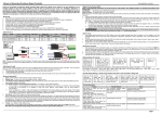
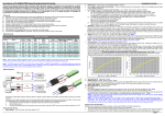
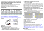
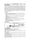
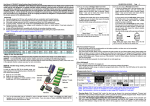
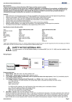
User Manual of PLATINUM PRO Series Brushless Speed Controller Thanks for purchasing our Electronic Speed Controller (ESC). High power system for RC model can be very dangerous, so please read this manual carefully. In that we have no control over the correct use, installation, application, or maintenance of our products, no liability shall be assumed nor accepted for any damages, losses or costs resulting from the use of the product. Any claims arising from the operating, failure or malfunctioning etc. will be denied. We assume no liability for personal injury, property damage or consequential damages resulting from our product or our workmanship. As far as is legally permitted, the obligation to compensation is limited to the invoice amount of the affected product. ǏFeaturesǐ Ź High performance microprocessor brings out the best compatibility with all kinds of motors and the highest driving efficiency. Ź Maximum motor speed: 210000 RPM (2 poles), 70000 RPM (6 poles), 35000 RPM (12 poles). Ź 3 start modes: Normal / Soft / Very-Soft, compatible with fixed-wing aircraft and helicopter. Ź Throttle range can be configured to be compatible with all transmitters currently available on market. Ź Smooth, linear, quick and precise throttle response. Ź Separate voltage regulator IC for microprocessor to get a better anti-jamming capability. Ź Multiple protection features: Low-voltage cut-off protection / over-heat protection / throttle signal loss protection. Ź The output of the built-in BEC is switchable by user programming (5.25V or 6.0V). Ź With governor mode for helicopter. Ź USB supported. The firmware of the ESC can be updated by the USB adapter. Ź Several kinds of Program Cards are supported. Very easy to program the ESC at home or at the field. ǏSpecificationsǐ 2. 3. 4. 5. 6. Platinum Pro Series Normal Voltage ESC˄Supports 2 to 6 Cells Lipo) Class BEC Model Cont. Burst Mode Current Current 30A 40A 60A 80A 100A 150A High 70A 120A Platinum-30A-OPTO Platinum-40A Platinum-60A Platinum-80A Platinum-100A Platinum-150A-OPTO Voltage ESC˄Supports Platinum-70A-HV Platinum-120A-HV 30A 40A 40A 60A 60A 90A 80A 120A 100A 150A 150A 220A 5 to 12 Cells Lipo) 70A 105A 120A 180A None Switch Switch Swicth Switch None BEC Output None 5.25V or 6V, 5.25V or 6V, 5.25V or 6V, 5.25V or 6V, None None None Yes Battery Cells Lipo NiMH 2-6 5-18 2-6 5-18 2-6 5-18 2-6 5-18 2-6 5-18 2-6 5-18 None None Yes Yes 5-12 5-12 3A 4A 4A 4A User Programmabl Yes Yes Yes Yes Yes 15-36 15-36 31g 38g 68g 77g 82g 125g Size L*W*H 55*25*12 59*27*12 70*34*16 70*34*16 70*34*16 88*55*15 82g 125g 70*34*16 88*55*15 Weight 7. HW-SM004DUL-20130502 Battery Type˖*Lithium (Lipo or Li-ion) / NiMH, GHIDXOWLV³/Lthium´. Low Voltage Protection Mode (CutOff Mode)˖*Soft Cut (Gradually reduce the output power) / Hard Cut (Immediately stop the output power). Default is ³Soft Cut´. Low Voltage Protection Threshold (Cutoff Threshold)˖Low / *Middle / High / CustomGHIDXOWLV³Middle´ 4) For lithium batteries, the cutoff threshold of the whole battery pack is calculated according to the cells number. For normal voltage ESC (supports 2-6 cells Lipo), the Low / Middle / High value for each cell is: 2.85V / 3.15V / 3.30V For high voltage ESC (supports 5-12 cells Lipo), the Low / Middle / High value for each cell is: 2.75V / 3.0V / 3.25V For example, if the cutoff threshold is set to ³Middle´, then the threshold for a 3 cells Lipo battery pack is 3.15*3=9.45V. 5) For NiMH and NiCd batteries, the cutoff threshold of the whole battery pack is calculated as follows: Low : 50% of the battery¶s battery¶s full charged voltage Middle: 62.5% of the battery¶s full charged voltage High: 75% of the battery¶s full charged voltage 6) If this programmable item is set to ³Custom´, that means you can set the cutoff threshold for the whole battery pack very accurately with the step of ±0.1V. The LCD program box or PC software (through USB adapter) is needed to customize the value. Start Mode˖*Normal / Soft / Very-SRIWGHIDXOWLV³NRUPDO´ ³1RUPDO´LVpreferred for fixed-ZLQJDLUFUDIW³6RIW´ or ³Very-SRIW´DUHpreferred for helicopters. The initial acceleration of the ³Soft´ and ³Very-Soft´ modes are slower than ³Normal´ mode, usually it takes 3 second for ³Soft´ mode or 8 seconds for ³Very-Soft´ mode from 0% throttle advance to full throttle. After startup, if the throttle is closed (throttle stick is moved to the bottom position) and opened again (throttle stick is moved upwards) within 3 seconds, the restart will be temporarily changed to ³Normal´ mode to get rid of the chances of a crash caused by slow throttle response. This special design is usedful for aerobatic flight. Timing˖0°/ 3.75° / 7.5° / 11.25° / *15° / 18.75° / 22.5° / 26.25°, default is 15°. Note3 Usually, low timing value is suitable for most motors. But there are many differences among structures and parameters of different motors so please try and select the most suitable timing value according to the motor you are just using. The correct timing value makes the motor run smoothly. And generally, higher timing value brings out higher output power and higher speed. Note3: After changing the timing setting, please test your RC model on ground prior to flight! Governor Mode˖*Off / Governor Low / Governor High, default is ³Off´ If the governor mode is activated, the ESC will try its best to hold the motor speed at a fixed value. (Usually the throttle curve is a horizontal line, you can change the preset motor speed by changing the height of this line). The speed range of ³Governor Low´ mode is 10000RPM to 45000RPM for 2 poles brushless motor, ³Governor High´ mode is 46000RPM to 200000RPM for 2 poles brushless motor. In order to calculate the speed of the main rotor blades of your helicopter, you need to know the motor poles number and the gear rate of main drive gear vs. the pinion. For example, if you are using a 6 poles motor (that is: 3 pair poles), and the main drive gear is 150T, the pinion is 13T, so you can calculate as follows: The rotation speed for the main rotor blades = (The speed of 2 poles motor * 13) / 3 / 150 When you adjust the throttle curve, please make sure that the motor can run at this preset speed even if the motor load is heaviest. Please note that the governor mode function is automatically disabled if the throttle volume is less than 60%. Note1: BEC means the ³Battery Elimination Circuit´. It is a DC-DC voltage regulator to supply the receiver and other equipments from the main battery pack. With the build-in BEC of an ESC, the receiver needn¶t to be supplied with an additional battery pack. Note2: 7KH(6&QDPHG³[[[-2372´or ³xxx-HV´ KDVQ¶WDEXLOW-in BEC, an UBEC (Ultimate-BEC) or an individual battery pack should be used to power the receiver. And an individual battery pack is needed to power the program card when setting the programmable values of such ESCs, please read the user manual of program card for reference. ǏWiring Diagramǐ Reserved Item #1˖Reserved for future. PWM Frequency: *12KHz / 8.+]GHIDXOWLV³.+]´ For some motors with high KV (high speed) and many poles, the 12KHz PWM frequency may let them work more smoothly. But the higher PWM frequency will make the ESC hotter. Generally, the 8KHz PWM frequency is suitable for most motors. 10. Built-In BEC Output: *5.25V / 6V, default is 5.25V. 11. Reserved Item #2: Reserved for future. 12. Lipo Cells: For normal voltage ESC (supports 2-6 cells Lipo), the values are *Auto / 2S / 3S / 4S / 5S / 6S, the default is ³Auto´; Note4 For high voltage ESC (supports 5-12 cells Lipo), the values are *Auto / 5S / 6S / 8S / 10S / 12S, the default is ³Auto´. This programmable item is available for lithium battery. In the startup process, the motor will emiWVVHYHUDO³%HHS-´WRQHVWRUHSUHVHQWWKH Lipo cells number, it is helpful for you to check whether it is coincident with the actual battery pack or not. Note5 Note4: If you choose ³Auto´, the ESC may mistakenly judge the battery cells when the voltage is less than 3.7V/Cell, so we strongly VXJJHVWVHWWLQJWKH³/LSR&HOOV´PDQXDOO\. Note5: For high voltage ESC (supports 5 to 12 cells Lipo), when the motor emits the ³Beep´ tones to represents the cells number, a long ³Beep²´ tone = 5 short ³Beep-´ tone. So 5S = ³Beep²´, 6S = ´Beep²Beep-´ (1 long 1 short), 8S=´Beep²Beep-Beep-Beep-´ (1 long 3 short), 10S= ³Beep²Beep²´ (2 long), 12S=´Beep²Beep²Beep-Beep-´ (2 long 2 short). While for normal voltage ESC (supports 2 to 6 cells Lipo), we still use 5 short ³Beep-´ tones to represent 5S lipo, and 6 short ³Beep-´ tones to represent 6S lipo. 8. 9. The Platinum-150A-OPTO, Platinum-70A-HV, Platinum-120A-HV, Pentium-80A-HV and Pentium-100A-HV ESC use the new anti-spark structure. There are a pair of bullet connectors and a thin red wire attached with the positive input wire (red color, thick) of the ESC. They are used to eliminate sparks when the battery pack is connecting with the ESC. Please use it in the following sequence: 1. Disconnect the two bullet connectors on the positive input wire (red color, thick) of the ESC. 2. Connect battery wires. 3. Connect the bullet connectors on the positive input wire (red color, thick) of the ESC as soon as you hear WKHVSHFLDOWRQH³ƈ´ ǏProgrammable Itemsǐ 1. Brake Setting˖*Off / Soft / Hard / Very Hard, default is ³Off´. ǏBegin To Use The New ESC ǐ Please check the wiring and connections carefully, and then start the ESC in the following sequences: 1. Move the throttle stick to the bottom position and then switch on the transmitter. 2. Connect the battery pack to the ESC, the ESC begins the self-test process, a special tone ³ƈ 123´ is emitted, which means the voltage of the battery pack is in normal range, and then N ³Beep´ tones will be emitted, means the number of lipo battery cells. Finally a long page 1 User Manual of PLATINUM PRO Series Brushless Speed Controller 3. HW-SM004DUL-20130502 ³Beep²´ tone will be emitted, which means the self-test is OK, the aircraft or helicopter is ready to go flying. If nothing is happened, please check the battery pack and all the connections; If a special tone ³ƈ ´ is emitted after 2 Beep tones (³Beep-Beep-´), means the ESC has entered the program mode, it is because the throttle channel of your transmitter is reversed, please set it correctly; If the red LED flashes very quickly (2 times per second), means the input voltage is too low or too high, please check your battery¶s voltage. VERY IMPORTANT! Because different transmitter has different throttle range, you need to calibrate the throttle range and let the ESC remember it. Please read the instruction on the left bottom of this page ------³Throttle Range Setting´. After correctly setting the throttle range, the red LED lights when the throttle stick is moved to the top position (Maximum throttle). ǐ ǏAlert Toneǐ 1. Input voltage is abnormal: The ESC begins to check the voltage when the battery pack is connected, if the voltage is not in the acceptable range, such an alert WRQH ZLOO EH HPLWWHG ³Beep-Beep-, Beep-Beep-´ (Every ³Beep-Beep-´ has a time interval of about 1 second), and at the same time, the red LED also flashes. 2. Throttle signal is lost: When the ESC can¶t detect the normal throttle signal, such an alert WRQHZLOOEHHPLWWHG³Beep-, Beep-, Beep-´. (Every ³Beep-´ has a time interval of about 2 seconds) 3. Throttle stick is not in the bottom position: When the throttle stick is not in the bottom (lowest) position, a very rapid alert tone will be emitted: ³Beep-, Beep-, Beep-´. (Every ³Beep-´ has a time interval of about 0.25 second.) ǐ ǏProtection Functionǐ 1. Abnormal startup protection: If the motor fails to start within 2 seconds of throttle application, the ESC will cut-off the output power. In this case, the throttle stick MUST be moved to the bottom position again to restart the motor. (This happens in the following cases: The connection between ESC and motor is not reliable, the propeller or the motor is blocked, the gearbox is damaged, etc.) 2. Over-heat protection: When the temperature of the ESC is over a factory-preset degree, the ESC will reduce the output power. 3. Throttle signal loss protection: The ESC will cutoff the output power if throttle signal is lost for more than 0.25 second, the output power will be resumed as soon as the throttle signal is normal again. ǏProgram The ESC With The Transmitterǐ ǐ(4 Setps) 1. 2. 3. 4. 1. Enter program mode Select programmable items 6HWLWHP¶s value (Programmable value) Exit program mode 2. Select programmable items After entering program mode, you will hear 14 groups of ³Beep´ tones in a loop with the following sequence. If you move the throttle stick to bottom position within 3 seconds after one kind of tones, the corresponding item will be selected. Enter program mode a) Switch on transmitter, move the throttle stick to the top position. b) Connect the battery pack to the ESC, a special tone ³ƈ123´ emits, that means the battery supply is OK. c) Wait for 2 seconds, the motor will emit ³Beep-Beep-´ tone. d) Wait for another 5 seconds, special tone ´ emits, that means the like ³ƈ program mode is entered Trouble Possible Reason The connection between battery pack and ESC is not correct Input voltage is abnormal, too high or too low. The motor stop running while in working state Throttle signal is irregular or lost Check the receiver and transmitter Check the control cable of the ESC The throttle stick is not in the bottom (lowest) position Move the throttle stick to bottom position Set the throttle trimmer to neutral or even lower. Direction of the throttle channel is reversed, so the ESC has entered the program mode The connection between ESC and the motor need to be changed. Throttle signal is lost Set the direction of throttle channel correctly (Please refer to the user manual of your transmitter) Swap any two wire connections between ESC and motor Check the receiver and transmitter Check the control cable of throttle channel Land RC model as soon as possible, and replace the battery pack Check all the connections: battery pack connection, throttle signal cable, motor connections, etc. Several ³Beep-´ tones emits to represent the number of lipo battery cells (1 short tone) Battery Type (2 short tones) 3 BBB Cutoff Mode (3 short tones) 4 BBBB Cutoff Threshold (4 short tones) 5 Beep² Start Mode (1 long tone) 6 Beep² B Timing (1 long 1 short) 7 Beep² BB Governor Mode (1 long 2 short) 8 Beep² BBB Reserved Item #1 (1 long 3 short) 9 Beep² BBBB PWM Frequency (1 long 4 short) 10 Beep² Beep² Built-in BEC Output (2 long tones) 11 Beep² Beep² B Reserved Item #2 (2 long 1 short) 12 Beep² Beep² BB Lipo Cells (2 long 2 short) 13 Beep² Beep² Beep² B Reset All To Defaults (3 long 1 short) (3 long 2 short) Note: ³%HHS²´ means a long ³Beep´ tone, ³B´ means a short ³Beep´ tone. Usually, 1 long ³%HHS²´ VKRUW³B´. Check the power connection. Replace the connector with new one Check the voltage of battery pack ǏNormal Startup Procedureǐ ǐ Connect the battery pack to the ESC, a special tone ³ƈ123´ emits, that means the battery supply is OK Brake BB Action ESC has entered Low Voltage Protection mode Some connections are not reliable Move the throttle stick to bottom position and then switch on your transmitter B 2 14 Beep² Beep² Beep² BB Exit ǏTrouble Shootingǐ ǐ After power on, motor does not work, no sound is emitted After power on, motor does not work, such an alert tone is emitted and the red LED flashes at the same time. ³Beep-Beep-, Beep-Beep-´ (Every ³Beep-Beep-´ has a time interval of about 1 second) After power on, motor does not work, such an alert tone is emitted: ³Beep-, Beep-, Beep- ´(Every ³Beep-´ has a time interval of about 2 seconds) After power on, motor does not work, such an alert tone is emitted: ³Beep-, Beep-, Beep-´ (Every ³Beep-´ has a time interval of about 0.25 second) After power on, motor does not work, a special tone ³ƈ ´ is emitted after 2 ³Beep´ tones (Beep-Beep-) The motor runs in the opposite direction 1 As soon as the self-test process is finished, a long ³Beep²´ tone will be emitted Move the throttle stick upwards to go flying now 3. Set item value (Programmable value) 4. Exit program mode <RXZLOOKHDUVHYHUDO³%HHS´WRQHVLQORRS6HWWKHYDOXHPDWFKLQJto a tone by moving the WKURWWOHVWLFNWRWRSSRVLWLRQZKHQ\RXKHDUWKHWRQHWKHQDVSHFLDOWRQH³ƈ ´HPLWVWKDW means the value is set and saved. (Keep the throttle stick at the top position, you will go back to Step #2 and you can select other items; Or Move the stick to bottom position within 2 seconds will exit program mode directly) There are 2 ways to exit the program mode: a) In Step #3, after VSHFLDO WRQH ³ƈ ´ please move the throttle stick to the bottom position within 2 seconds. b) In Step #2, after tone Beep²Beep²Beep ²BB´ (3 long 2 short Beep tones, that is the item #14), move the throttle stick to the bottom position within 3 seconds. Beep 1 short 2 short 3 short 4 short *Off Soft Hard Very Hard *LiPo NiMH Custom 1 long 1 long 1 short 1 long 2 short 1 long 3 short *15° 18.75° 22.5° 26.25° Items Brake Battery Type Cutoff Mode Cutoff Threshold Start Mode Timing Governor Mode *Soft Cut Hard Cut Low *Middle High *Normal Soft Very Soft 3.75° 7.5° 0° *Off 11.25° Governor Governor Low High Reserved Item #1 PWM Frequency *12KHz 8KHz Built-in BEC Output *5.25V 6V Reserved Item #2 Lipo Cells *Auto 2S 3S 4S 5S 6S *Auto 5S 6S 8S 10S 12S ĕ For normal ESC (2 to 6S Lipo) ĕ For high voltage ESC (5 to 12S Lipo) The value with * symbol is the factory-preset value (That is: default value). Note6: After setting the programmable items by the throttle stick or a Program Card, you will hear 5 long ³Beep²´ tones when the ESC exits the program mode. You can restart the ESC after 5 seconds. ǏThrottle Range Settingǐ ǐ Switch on the transmitter, and then move the throttle stick to top position Connect battery pack to the ESC, a special tone ³ƈ123´ emits, that means the battery supply is OK, then wait for 2 seconds ³Beep-Beep-´ tone emits, that means the highest point of throttle range has been correctly confirmed Move throttle stick to the bottom position, several ³Beep-´ tones emits to represent the number of Lipo battery cells A long ³Beep²´ tone emits, means the lowest position of throttle range has been confirmed page 2