1
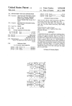
O
Unlted States Patent [19]
[11]
4,386,333
Dillan
[45]
May 31, 1983
[54]
UNIVERSAL ELECTRICAL CONNECTION I
APPARATUS
[75] Inventor:
.
George 0. Dillan, Boulder County,
C°1°-
[73] Assignee:
7600749
958885
,
8/ 1976 Netherlands .................... .. 339/32 R
5/1964 United Kingdom ......... .. 323/340x
OTHER PUBLICATIONS
IBM Technical Disclosure Bulletin, “Copier/Collator
International Business Machines
- Corporation, Armonk, NY.
Apparatus”, A- J- B0116, l H- Hubbard, J- P- Jord?n, H
Kelm, R. J. LeClere and S. W. Zieg, 12/76 pp. 2444,
2445.
[21] APPL No" 317’108
IBM Technical Disclosure Bulletin, “Connection
[22] Filed:
Alignment Pin With Selectable Key”, C. R. Pettie, pp.
Nov. 2, 1981
[51]
Int. c1.3 ............................................ .. H01F 27/04
624’ 625’ 7/72'
[52]
us. Cl. .................................. .. 336/107; 323/328;
1 0- Penney Sen/Ice Manual’ “Black and Whlte Televl
323/340; 323/341; 336/149; 336/150; 339/13
[513]
,
_
Sion Model 1038B” (7 99-) Form N9 28129_55—1
P; 339/31 M; 339/32 R; 339 /32 M; 339/33-
J. C. Penney Manual “Location and Operation of Cus
Field of Search‘ ..................... .. 336/107, 150, 149;
tomer Controls and Battery Model 1038B” (4 99-),
339/18 P, 31 M, 32 R, 32 M, 33; 323/328, 340,
341
Form No. 2812953-1.
IBM Series III Copier/Duplicator Service Manual, pp.
.
[56]
162, 163, Form No. 241-5928—0.
References and
Electronic Design, 11/22/80, p. 296.
U.S. PATENT DOCUMENTS
_
v
18;
,
_
,
2,417,928
2,930,019
29121-13111" '
c
an
.. ...
3/1947 Guernsey .
3/ 1960 Hubbell
173/361
-
..... .. 173/361
....... .. 339/31
6/1961
Aarlaht
........... ..
3,034,000
5/1962
Todd _ _ _ _ _ ’ . _
‘ _ ' . _ “ 336/150 X
3,082,302 3/1963 Rumble
2/1964 Hubbell ...... ..
4/1974 Ferdelman
4,053,788 10/1977
_
Assistant Examiner-Susan Steward
. . . . . . . . . . . . . ..
2,989,719
3,l20,985
3,802,159
[
Primary Exammer—A. T. Grlmley
339/31
...... .. zoo/51.03
3.39/31 M
....... ..
Robie .................................. .. 307/11
FOREIGN PATENT DOCUMENTS
1056222 4/1959 Fed. Rep. of Germany .
267689 4/ 1966 Fed. Rep. of Germany .... .. 336/150
2243825 8/1972 Fed. Rep. of Germany .
1503482 10/ 1967 France .
1545854 10/1968 France .
__
Attorney’ Agent’ or F'rm Gunter A‘ Hauptma“
[57]
ABSTRACT
.
.
-
.
.
Different llne-cord sets connect an electrical devlce to
different supply voltages, assuring that the Supply volt
age matches the device. Each line-cord set has a
uniquely keyed socket and a wall
A device recep
tacle receives the line-cord’s keyed socket. An adjust
able key on the device mates with the socket’s key and
rejects nonmating sockets to admit the socket into the
receptacle and adjusts the device’s input voltage to
match the supply voltage.
6 Claims, 9 Drawing Figures
US. Patent‘ May31, 1983
Sheet 1 of7
4,386,333
US. Patent
May 31, 1983
Sheet 2 of7
4,386,333
US. Patent
May 31, 1983
Sheet 3 of?
A l
I
//
4,386,333
US. Patent
May 31, 1983
Sheet 4 of 7
4,386,333
a8
5ma
NEH
r-r
ll
IU
II
/
llHll
1 x2:
US‘. Patent
May 31, 1983
Sheet 5 of 7
4,386,333
- Na
E2x»03Q<>
9;
?i|
_____________________J
uwL
§§\.uan=1___w
m
n
30x» m
u
no;
u
.
_
_
.2“.
vé
- _
_
"0.1”
3‘2,
US. Patent
May 31, 1983
Sheet 6 of 7
US. Patent
May 31, 1983
Sheet 7 of 7
4,386,333
4,386,333
1
2
The prior art does not teach a single device recepta
cle uniquely mated to each one of a multiplicity of line
cord sets and to the device’s power supply, wherein
inadvertent mismatches cannot occur.
UNIVERSAL ELECTRICAL CONNECTION
APPARATUS
BACKGROUND OF THE INVENTION
5
The invention provides plural plug and socket line
cord sets, usable with a device having a variable power
1. Field of the Invention
interface, for assuring that the plug’s supply voltage
The invention relates to apparatus for connecting an
matches the device’s input voltage. Each line-cord set
electrical device to a power source and, more particu
has two essentially permanently attached end connec
10 tors: a keyed socket and a wall plug. The keyed socket
different source voltages.
has a unique predetermined con?guration for the one
2. Description of the Prior Art
supply voltage to which the wall plug at the other end
Electrical devices, such as copiers, computers, audio
is designed to connect. A device receptacle connected
components, household appliances, etc., frequently op
to the device’s power interface receives the line-cord’s
erate on only one voltage but must be used with differ
keyed socket. An adjustable key on the device mates
ent power supply voltages. For example, a 115 VAC 60
with the keyed socket’s con?guration and rejects non
Hz copier wired with a 115 VAC 60 Hz style plug may
mating line-cord sockets. Adjusting the receptacle’s key
have to be used where only a 230 VAC 60 Hz power
to mate with the keyed socket plug; (a) admits the line
supply outlet is available. Substitution of a 230 VAC 60
larly, universally adapting a single-voltage device to
cord socket into the receptacle and (b) varies the de
vice’s power interface to match the device’s input volt
age to the supply voltage for which the wall plug is
,Hz plug together with appropriate wire reconnections
permit 115 VAC copier operation from the 230 VAC
outlet. However, serious hazards to an operator and
‘machine safety are created. For example, a plug or
designed.
socket wiring error introduces 230 VAC to copier parts
designed for 110' VAC. The reverse situation creates
analogous problems. In addition to the hazards of rewir
ing a 230 VAC device for 110 VAC outlets, the lower
BRIEF DESCRIPTION OF THE DRAWINGS
FIG. 1A illustrates a device incorporating the inven
tion.
FIGS. 1B—1D show mechanical aspects of the device
supply voltage 'will probably not effectively operate
most 230 VAC devices.
receptacle.
'
FIG. 2 shows the invention schematically.
Electrical devices incorporate solutions to some of
FIG. 3 details the variable voltage converter of FIG.
2. A second voltage converter embodiment appears in
FIG. 4.
FIGS. 5 and 6 illustrate two line-cord sets usable in
these problems. The 115 VAC IBM Series III copier
connects directly to 230 VAC power supply voltage
through appropriate wiring between its internal compo
nents and a 230 VAC plug. A line cord adapter, when
placed between the 230 VAC plug and a 115 VAC
the invention.
power supply socket, provides essential wiring inter
DETAILED DESCRIPTION
connections, but does not affect the copier’s voltage
requirements. Voltage switches advertised in ELEC
TRONIC DESIGN, Nov. 22, 1980, page 296, permit
different power supply voltage connections, but do not
insure that the switch positions match the connected
voltages. IBM TECHNICAL DISCLOSURE BUL
LETIN, December 1976, pages 2444 and 2445 describe
a special circuit for protecting a copier/collator from
being inadvertently plugged into the wrong line. Keyed
mating plugs and sockets appear in IBM TECHNICAL
DISCLOSURE BULLETIN, July 1972, pages 624 and
625, and German Publication No. 2,243,825, Mar. 14,
1974. Alternatively, separate device-mounted sockets
for each possible power supply voltage and matching,
removable line-cord sets for each power source voltage
may be provided with the device. The latter solution
requires circuits for removing electrical potential from
In FIG. 1A, an electrical device 101, such as a com
puter, ampli?er, household appliance, etc., carries an
electrical connector 102 for receiving electrical power
supply voltage when an appropriate connector is in
serted into a receptacle 103. A rotatable disc 104 de?nes
insertable connectors, barring other connectors, in ac
cordance with the particular supply voltage for which
the device 101 is conditioned by the disc 104. Typically,
45 electrical device 101 operates on a supply voltage of 115
VAC. Therefore, physically distinguishable connectors
associated with supply voltages of, for example, 105
VAC, 115 VAC, 209 VAC, and 230 VAC, are insert
able into the receptacle 103, depending upon the disc
50
104 position. As the disc 104 is rotated, the different
connectors become insertable. Simultaneously, the de
vice 101 is conditioned for the correspondingly differ
ent supply voltages. Actual voltage applied to circuits
unused sockets. French Pat. No. 1,545,854 discloses two
inside the device 101 therefore remains at, by way of
sockets, one covered, alternately selectable, connected 55 example, approximately 115 VAC.
to a power supply voltage changing switch. U.S. Pat.
The electrical connector 102 of FIG. 1A appears in
Nos. 2,930,019 and 2,989,719 disclose plugs and sockets
more detail in FIG. 1B. The receptacle 103 includes a
adjustable for a plurality of power sources. However,
grounding conductor 105, two phase conductors 106
since each must be manually rewired for different volt
and a neutral conductor 107 connectable to a mating
age sources, a voltage mismatch is possible. Portable 60 socket arranged to receive the conductors 105—107_. The
radios provide one receptacle both for 110 VAC opera
disc 104 rotates peripheral keys 109-112 and a switch
tion and, specially slotted, for 12 VDC automobile op
113 when an operator turns a screwdriver slot 108 or
eration. A 12 VDC socket projection switches the
otherwise grasps and turns the disc 104. One of keys
power source directly into the radio’s DC power sup
109-112 locks into position adjacent the receptacle 103
ply. In French Pat. No. 1,503,482, a notched dial rests 65 to mate with one socket and bar others. For example, in
. on a plug inserted into an electric razor. While the dial
the position shown in FIG. 1B, a socket designed for a
operates a circuit adapting the razor’s voltage, operator
105 VAC power supply mates with key 109. Additional
error connects the wrong power supply voltage.
power supply values appear on the view of disc 104 in
3
4,386,333
FIG. 1C. FIG. 1D, which is section 1D, through FIG.
1C, shows how disc 104 rotation operates rotary switch
4
FIGS. 5 and 6 illustrate two line-cord set 201 designs
usable in the invention. In both FIGS. 5 and 6, keyed
socket 202 and a wall plug 203 are connected together
113. A shaft 114 connects disc 104 to switch rotor 117
which completes contacts, in a well known manner, as
by a line cord 204. It is important that the socket, cord
and plugs 202-204 be integrally formed, as by molding,
it steps through positions held by a ball detent 115 and
spring 116.
to bar tampering. In FIG. 5, the wall plug 203 is in
FIG. 2 illustrates an electrical device 101 carrying an
tended for insertion into a 115 VAC wall socket, not
electrical connector 102. Receptacle 103 receives a
mating keyed socket 202 connected to a wall plug 203
shown, requiring a wall plug 203 with three connectors
705-707 arranged as shown. The corresponding keyed
socket 202 115 VAC key 510 identi?es the potentials
via a line cord 204 of a line-cord set 201. Receptacle 103
also connects to output cable 205 and output socket 206
present at conductors 505-507: 115 VAC between the Y
phase conductor 506 and the neutral conductor 507. In
the case of the line-cord set 201 in FIG. 6, 230 VAC
appear between the Y and X phase conductors 606.
through rotary switch 113. An output plug 207 is in
serted into output socket 206 to ultimately connect
cable 208 and utilization circuit 209 to power supply
voltage at wall plug 203. The actual voltage applied to
the utilization circuit 209 depends upon the position of
disc 104 and the mating keyed socket 202 on line-cord
In operation, electrical device 101 is installed by
choosing the line-cord set 201 that has a voltage desig
set 201.
The receptacle 103 and disc 104 in FIG. 3 are ar
and a wall plug 203 which ?ts into the wall socket
nation matching the power supply voltage available,
provided for that power supply voltage. The disc 104 is
then rotated to line up the keys 109-112 corresponding
to the selected voltage and the keyed socket 202 is
inserted into the receptacle 103. The selected position of
disc 104 provides a rotary switch 113 position that
ranged to receive a mating keyed socket 202 connected
to a 115 VAC wall plug 203, as shown in FIG. 5. Rota
tion of the disc 104 two steps (in either direction) rear
ranges the receptacle to receive instead a socket 202
connected to a 230 VAC wall' plug 203, as shown in
maintains the voltage at output socket 206 the same for
FIG. 6. The choices of keys 109-112 and the corre
"widely different wall socket power supply voltages. If,
sponding voltages are arbitrary. In FIG. 3, the rotary
for example, the wall plug 203 in FIG. 5 connects to 115
VAC, this voltage appears across conductors 706-707,
506-507 and 106(Y)-107 (FIG. 3). With rotor 117 in the
104 rotates switch shaft 114. Receptacle 103 phase con 30 position shown in FIG. 3, 115 VAC at the Y and neutral
ductors 106 supply power supply voltage (in this exam
inputs of primary 302 of transformer 301, appears as 115
ple, 115 VAC) from wall plug 203 to transformer 301
VAC at conductors 306-307. If instead, wall plug 203 in
switch 113, rotor 117, connects one at a time of switch
contacts 309-312 to one wire in output cable 205 as disc
connected to rotary switch 113. In the example of FIG.
3, the 115 VAC line-cord set 201 keyed socket 202
FIG. 6 connects to a 230 VAC power supply, this volt
age appears in connectors 806, 606 and 106. However,‘
(FIG. 5) could be inserted into the receptacle 103 only
rotor 117 now will be at contact 312 and 115 VAC still
after the disc 104 was rotated to position switch rotor
117 at the 115 VAC switch contact 310. This switch
contact 310 connects to a transformer 301 secondary
303 output Y><l which provides the same voltage as
will appear at conductors 306-307.
was applied at transformer 301 primary 302 input Y
connected to one of the phase conductors 106. If, in
stead, the 230 VAC line-cord set 201 (FIG. 6) had been
. used, the disc 104 would have positioned the rotor at
the 230 VAC contact 312 connected to the same output
‘
'
'
1. Apparatus for connecting an electrical device to a
plurality of supply voltages, including:
Y>< 1. As a result, 230 VAC (between phase conductors
106) which is 115 VAC (between Y conductor 106 and
a voltage converter, having a control, a voltage out
put connected to the device, and a voltage input,
the converter being operable by the control to vary
conductor 107) appears as 115 VAC on the wire in
output cable 205 connected to rotor 117. Similarly, 105
VAC, 115 VAC, 209 VAC or 230 VAC between the
phase conductors 106 of receptacle 103 always appears
‘
While the invention has been particularly shown and
described with reference to preferred embodiments
thereof, it will be understood by those skilled in the art
that various changes in form and details may be made
therein without departing from the spirit and scope of
the invention.
What is claimed is:
the input to output voltage ratio;
50
a plurality of line-cord sets each having a plug at one
as 115 VAC between phase conductor 306 and neutral
end mateable with a prede?ned supply voltage and
conductor 307 of output socket 206; because, the disc
a connector at the other end having a unique shape
104 and therefore the rotor 117 must be appropriately
moved to enable the receptacle 103 to receive the corre
identifying the plug’s supply voltage;
‘
a voltage receptacle connected to the converter input
spondingly keyed socket 202.
As shown in FIG. 3, the receptacle 103 neutral con
ductor 107 is connected to the transformer 301 primary
302. The Y conductor 106 connects to the other end of
primary 302, while the X conductor 106 is not used. The
ground conductor 105 may connect via output cable 60
205 to ground connector 305 of output socket 206.
for receiving one line-cord connector at a time; and
mechanical keys, attached to the converter’s control,
each positionable to de?ne a connector receivable
by the receptacle and bar other connectors;
whereby, operation of the control to permit the re
ceptacle to receive a connector varies the input to
output voltage to provide substantially the same‘
output voltage for different supply voltages.
Other voltage conversion devices may be used in place
of transformer 301. For example, the transformer 301
2. The apparatus of claim 1 whereinthe voltage con
may be omitted or replaced by a “Y” or “Delta” wound
verter is a multitap transformer'connected to a switch '
transformer using both X and Y conductors 106. In 65 moved in accordance with mechanical key positions to
FIG. 4, an autotransformer winding 401 connects to
select different taps and, therefore, output voltages.
transformer 301 input wires 304 and output wires 308 in
3. Apparatus for connecting an electrical device to a
place of the device in FIG. 3.
plurality of supply voltages, including:
5
4,386,333
a voltage converter, having a control, a voltage out
put connected to the device, and a voltage input,
the converter being operable by the control to vary
the input to output voltage ratio;
a plurality of line-cord sets each having a plug at one
end mateable with a prede?ned supply voltage and
a connector at the other end having a unique shape
identifying the plug’s supply voltage;
end with pins mateable with a prede?ned voltage
a voltage receptacle connected to the converter input
supply and a connector at the other end having a
for receiving one line-cord connector at a time; and 10
mechanical keys, formed on the circumference of a
disc attached to the converter’s control, the disc
being rotatable to bring one key at a time into a
position to de?ne a connector receivable by the
receptacle and bar other connectors;
whereby, rotation of the disc operates the control to
permit the receptacle to receive a connector, and
stantially the same output voltage for different
supply voltages.
unique shape identifying the plug;
a voltage receptacle connected to the switch input for
receiving one line-cord connector at a time; and
indentations, formed on the circumference of a disc
attached to the switch’s manual control, the disc
being rotatable to bring one indentation at a time
into a position to mate with a connector shape
receivable by the receptacle and to bar other con
nector shapes;
whereby, rotation of the disc permits the receptacle
varies the input to output voltage to provide sub
20
to receive one mating connector, and varies the
input to output voltage to provide substantially one
4. The apparatus of claim 3 wherein the voltage con
output voltage for different voltage supplies.
verter is a multitap transformer connected to a switch
6. The apparatus of claim 5 wherein the voltage
moved in accordance with disc rotation to select differ
ent taps and, therefore, output voltages.
6
5. Apparatus for connecting an electrical device to
any one of a plurality of supply voltages, including:
a voltage switch, having a manual control, a voltage
output connected to the device, and a voltage in
put, the switch being operable by the manual con
trol to vary the input to output voltage ratio;
a plurality of line-cord sets each having a plug at one
switch includes a transformer.
25
30
35
45
50
55
65
*****