1
United States Patent [19]
[11] Patent Number:
Sato et a1.
[45]
[54] SEPARATION TYPE AIR CONDITIONER
3,305,234
Honda, Hyogo; Kazuho Uemura,
Japan
4/1974
Jul. 2, 1985
Masters ............................... .. 371/34
4,127,845 11/1978 Dansbach et a1.
[75] Inventors: Yasuo Sato; Akio Fukushima; Toshiro
Kaise, all of Shizuoka; Yoshiyuki
I-lyogo; Manabu Fujii, Hyogo, all of
Date of Patent:
4,526,010
4,183,223
I/l980 Alsenz
.......................
236/51
OTHER PUBLICATIONS
MCS-85 User’s Manual, Intel Corporation, 3065 Bow
ers Avenue, Santa Clara, Calif. 95051, Jan. 1978.
[73] Assignee: Mitsubishi Denki Kabushiki Kaisha,
Tokyo, Japan
Phase-Locked Loop Data Book, Exar Integrated Sys
[21] Appl. No.: 258,492
[22] Filed:
Apr. 28, 1981
[30]
Foreign Application Priority Data
Nov. 1979.
Primary Examiner—Harry Tanner
Attorney, Agent, or Firm-Sughrue, Mion, Zinn,
Macpeak, and Seas
Apr. 30, 1980 [JP]
Japan ................................. .. 55-57427
Dec. 2, 1980 [JP]
Japan ............................... .. 55-170160
. . . . . . . . . . . . ..
F25B 49/00
[57]
ABSTRACT
A separated-unit type air conditioner including indoor,
outdoor and remote controller units all of which are
[51]
Int. Cl.3
[52]
U.S. Cl. ...................................... .. 62/126; 62/180;
provided at different locations. Each of the units is
340/870.39; 371/34
provided with a single pair of connecting terminals to
[58]
.....
tems, Inc., PO. Box 62229, Sunnyvale, Calif. 94088,
Field of Search ............... .. 62/180, 126, 127, 125;
which a control device such as a microcomputer is
236/51, 94; 340/87039, 870.19, 825.57, 825.05;
coupled. Data transmission between units is carried out
on a single pair of connecting terminals utilizing a high
371/34
[56]
References Cited
U.S. PATENT DOCUMENTS
3,303,470
3,562,729
3,717,858
2/1967
2/1971
2/1973
Brixner et a1. ............... .. 340/825.57
Hurd ......... ..
340/870.39
Hadden ........................ .. 340/870.39
frequency modulated signal. A DC power supply is
provided in one of the indoor or outdoor units which
supplies DC power to the other units upon the single
pair of control lines.
10 Claims, 13 Drawing Figures
U.S. Patent Jul. 2, 1985
Sheet 1 Of7
FIG.‘ 7 PRIOR ART
101
'
OUTDOOR
UNIT
REMOTE
CONTROLLER
/@
FIG. 2
‘01¢ ,1
102
INDOOR
‘1:4( OUTDOOR
UNIT
UNIT
II
3\ '
REMOTE
CONTROLLER
T2
I05I
-
V21)
F/G. 3
1
101
15
102
113
105
114
1
20
REMOTE
CONTROLLER
17 18 Q 11
4,526,010
US. Patent 1111.2, 1985
Sheet2 017
4,526,010
FIG. 4
\LL
‘m.
_-
KEY
7g \,
22 2
-_
INPUT
n.
“TX
DC
CUT
~—Rx
De
CUT
20“
2030
/1
1
COMF?
DISP.
,
)
)
20L
201
/
‘208 1 11
EW' RECQ
FILTER
I.
E\
__
5K
j '
Vcc98 1
__
we” 5F
1
l
51-:
/
\ [5A
55
0c
x‘
C
COMP
ONT.
.
OUTP.
4
5L1
51
= 1
FW REc?
{I
5D
}
DC
“RX
c111
/
L,
/
5H
FILTER
L5-/..
__
15K
/
{F
13
=
@mm
——- Tx
.
|
Dc/151-:
/
CUT
w
com.
15L)
‘- RX
151
'
‘
15H
'
1
COMP.
OUTP.
5Q
14
-
_
SENS.
E
-
56 v0 H '. IW114
-
VCC1918 17
1
__2OD, 1 113
5
E
E
200
L
L‘
\
D
15D
C81
/
S
FlLTER
1530
151w
U.S. Patent Jul. 2, 1985
Sheet 3 of7
4,526,010
FIG. 5
113
114
,_____
__1
l____
“581521"""“$158
FIG. 6
________‘l5_
114
_____\
K\
20A
RMT
CNTRLR
INDOOR
CNTRLR
FIG. 7
115
113
FIG. 8
113
114
5A
208
FIG. 9
113i
114
US. Patent Jul. 2, 1.985
3msec
Sheet4of7
FIG. 70
1mSec
W
I" u "H!
_
4,526,010
"H! T
L
I ADDRESS
SlTART
DATA BIT 5
*“T
Bl
FIG. 77
START ADDRESS
BIT
BITS
ST
UNIT 5
AD1
ADQ
DATA
BlTS
DT1
ST AD
DT2
------- --
DT
C
TRANSMIT
|_L
RECEIVE
\
UNIT 15
TRANSMIT
[)Tn
\
»
RE¢EWE~E:L.
?
?‘R‘LANS
_J¥
'
‘I
Ri‘JéRsloN
TRANS.
1‘
,
éffécos
TRANS
1
4,526,010
2
for which cables used for its control signal lines are
readily available and the wiring of the cables can be
SEPARATION TYPE AIR CONDITIONER
readily and correctly achieved without affecting the
BACKGROUND OF THE INVENTION
The present invention relates to an improved separat
ed-unit type air conditioner, in which the compressor,
the heat exchangers, the air blowing devices, and the
appearance of a house or room in which the air condi
tioner is installed.
Another object of the invention is to provide an im
proved separated-unit type air conditioner in which
expansion valves are suitably and separately provided in
transmission of control signals between plural units
an indoor unit and an outdoor unit, and a remote con
forming the air conditioner is carried out through a
troller for these units is provided at a location different
from those of the indoor and outdoor units.
single pair of control signal lines.
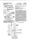
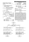
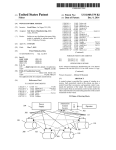
A conventional air conditioner of this general type is
shown in FIG. 1. In FIG. 1, reference numeral 1 desig
improved separated-unit type air conditioner which can
be installed without taking into account the polarities of
signal input terminals of a plurality of units forming the
air conditioner and installed separately.
A further object of the invention is to provide an
nates an indoor unit, 10 an outdoor unit, 20 a remote
controller, 101 a three-phase (or single-phase) electric
5
power line coupled to the indoor unit, 102 a three-phase
A still further object of the invention is to provide an
(or single-phase) electric power line coupled to the
improved
separated-unit type air conditioner in which,
outdoor unit, 103 control signal lines extending between
even though a single pair of control signals is employed,
the indoor unit 1 and the remote controller 20, 104
control signal lines between the indoor unit 1 and the 20 no data transmission and reception error is caused.
A particular object of the invention is to provide a
outdoor unit 10, and 105 refrigerant piping extending
separated-unit
type air conditioner in which a single
between the indoor unit and the outdoor unit.
pair
of
control
signal lines is used to supply electric
In general, in the conventional air conditioner, a
number of control signal lines 103 are laid between an
power from a DC source provided in one of the indoor
electronic controller (not shown) including a mi 25 unit and outdoor unit to the other and to a remote con
troller.
crocomputer provided in the indoor unit and the remote
In accordance with these and other objects of the
controller 20 including various operating switches, keys
invention, there is provided a separated-unit type air
and light emitting elements for display. In addition, a
conditioner having an indoor unit, an outdoor unit and
number of control-signal lines 104 are connected be
used to control a compressor, an air blower and various
a remote controller unit which are provided at three
different locations. The remote controller unit includes
operating valves (not shown) in the outdoor unit using
a power switch and a temperature setting means. The
tween the indoor unit and the outdoor unit which are
the outputs of the electronic controller in the indoor
unit, and to input the signals of a temperature control
remote controller unit is provided with a single pair of
?rst connecting terminals, ?rst control means for re
thermostat and various protecting device (not shown) 35 ceiving signals from the power switch and the room
in the outdoor unit to the electronic controller in the
temperature setting means to provide predetermined
indoor unit. A multiconductor cable having ten to
control outputs, data transmitting means connected
twenty conductors is employed for the control signal
between the ?rst control means and the ?rst connecting
lines 103, and a multiconductor cable having ?ve to ten
terminals to transmit data to the other units (in this case,
conductors is employed for the control signal lines 104. 40 the indoor unit and the outdoor unit), and data receiv
However, appropriate multiconductor cables, espe
ing means for receiving data from the other units. The
cially the multiconductor cable having ten to twenty
indoor unit includes an indoor heat exchanger, an air
conductors used as the control signal lines 103, are not
blowing motor and an air blowing fan. The indoor unit
readily available commercially. Even if a multiconduc
is provided with a single pair of second connecting
tor cable is available, the presence of the multiconduc 45
terminals, second control means for receiving a signal
tor cable may be rather unsightly. The appearance of
from a temperature sensor to provide a control output
the house or room may be maintained unchanged by
to drive the air blowing motor, data transmitting means
locating the cable in the walls of the house. However, in
interconnected
between the second control means and
this case, it is difficult to insert the cable into a conduit
tube, and accordingly the entire wiring operation is 50 the second connecting terminals to transmit data to the
other units (in this case, the remote controller unit and
considerably dif?cult. In addition, the employment of
the outdoor unit), and data receiving means for receiv
the multiconductor cable for the control signal lines 104
ing data from the other units. The outdoor unit includes
increases the time required for the installation and is
an outdoor heat exchanger, an air blowing motor, an air
liable to cause errors in the wiring since it is laid be
tween the indoor unit and the outdoor unit.
55 blowing fan and a compressor. As in the other two
Furthermore, the conventional air conditioner is dis - units, the outdoor unit is provided with a single pair of
third connecting terminals. The outdoor unit further
advantageous in that, where a sensor (not shown) is
includes third control means for receiving a signal from
added to the outdoor unit in order to save energy or to
a temperature sensor to provide control outputs to drive
control the air conditioner so that the occupants of the
room feel comfortable at all times, it is necessary to 60 the air blowing motor and the compressor, data trans
increase the number of control signal lines 104.
mitting means connected between the third connecting
terminals and the third control means (in this case, the
remote controller unit and the indoor unit), and data
SUMMARY OF THE INVENTION
Accordingly, an object-of the invention is to elimi
receiving means for receiving data from the other units.
nate all of the above-described difficulties accompany 65 A single pair of control signal lines is electrically con
ing a conventional separated-unit type air conditioner.
nected to each of the ?rst, second and third connecting
More speci?cally, an object of the invention is to pro
terminals through which data transmission and recep
vide an improved separated-unit type air conditioner
tion is carried out between the units.
3
4,526,010
Each data transmitting means may include a modula
4
DESCRIPTION OF THE PREFERRED
EMBODIMENTS
tor for high frequency modulating transmitted data on
the control signal lines. A DC power source may be
provided in one of the indoor unit and the outdoor unit
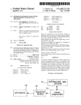
A preferred embodiment of the invention will be
described with reference to FIGS. 2 through 12. FIG. 2
is an explanatory diagram showing the arrangement of
for supplying DC power to each of the control means
with DC power being supplied through the control
signal lines to the other units. In the one of the indoor
and outdoor units in which the DC power source is not
provided, and in the remote control unit, there are pro
an example of a separate type air conditioner con
structed according to the invention. FIG.'3 is also an
explanatory diagram showing the arrangement in FIG.
2 in more detail. In FIGS. 2 and 3, reference numeral 1
vided circuits for non-polarizing the signals received on
the respective connecting terminals to which the con
trol signal lines are connected. This is preferably imple
mented by full-wave recti?er circuits. Direct current
blocking means is then provided at the connecting ter
designates an indoor unit, 10 an outdoor unit, 20 a re
mote controller, 101 a three-phase (or single-phase)
electric power line coupled to the indoor unit 1, 102 a
three-phase (or single-phase) electric power line cou
pled to the outdoor unit 10, 105 refrigerant piping con
minal sides of the data transmitting means and the data
receiving means of each of the units. Filter circuits may
nected between the indoor unit 1 and the outdoor unit
10, 113 a pair of control signal lines connected between
the indoor unit 1 and the remote controller 20, and 114
of a pair of control signal lines between the indoor unit
and the outdoor unit.
The indoor unit 1, as shown in FIG. 3, includes a heat
exchanger 2, a line flow fan 3 for supplying air to the
heat exchanger 2, a fan motor 4 connected to the power
line 101 to rotate the fan 3, an indoor electronic control
be also provided in each of the units.
To transmit data between any two of these three
units, the ?rst, second and third control means perform
an inversion return comparison in which, for data trans
mission and control, a data receiving side returns data
by inverting logic levels “1” and “0” of the received
data. The data transmitting side then compares the data
thus returned with the original transmitted data and 25 ler 5 for transmitting control signals through the pairs of
control signal lines 113 and 114 to the remote controller
outputs one of a coincidence signal and non-coinci
20 and an outdoor electronic controller and receiving
dence signal according to the results of the comparison.
control
signals therefrom to control the on-off opera
When a transmission error is detected a predetermined
tion of the fan motor 4, for instance. The indoor unit
number of times, the control means operates to stop
further includes a partition 6, a suction air temperature
operation of the air conditioner and to inform the user
controller 7 connected to the electronic controller 5,
of the abnormal condition.
and a blowing air temperature sensor 8 connected to the
The foregoing objects and other objects as well as
electronic controller 5.
characteristic features of the invention will become
The outdoor unit 10 includes a heat exchanger 11, a
more apparent from the following detailed description
propeller fan 12 for supplying air to the heat exchanger
and the appended claims when read in conjunction with
11, a fan motor 13 connected to the power line 102 to
the accompanying drawings.
rotate the fan 12, a compressor 14 for compressing the
BRIEF DESCRIPTION OF THE DRAWINGS
In the accompanying drawings:
refrigerant (not shown) which flows between the in
door unit 1 and the heat exchanger 2 through the refrig
40 erant piping 105, an outdoor electronic controller 15 for
transmitting control signals to the indoor electronic
FIG. 1 is an explanatory diagram showing the ar
rangement of a conventional separated-unit type air
controller 5 and to the remote controller 20 through the
conditioner;
pairs of control signal lines 113 and 114 and receiving
circuits of a remote controller, an indoor electronic
controller and an outdoor electronic controller in FIG.
the control signals between the indoor unit 1, the out
control signals therefrom to control the on-off opera
FIG. 2 is an explanatory diagram showing the ar
rangement of a preferred embodiment of a separated 45 tions of the fan motor 13 and the compressor, a capillary
tube 16, and a heat exchanger refrigerant temperature
unit type air conditioner according to the invention;
sensor 17 and an outdoor air temperature sensor 18
FIG. 3 is also an explanatory diagram showing the air
which are connected to the electronic controller 15.
conditioner in FIG. 2 in more detail;
As is apparent from FIGS. 2 and 3, in the air condi
FIG. 4 is a block diagram showing speci?c electrical
tioner of the invention, transmission and reception of
door unit 10 and the remote controller 20 are carried
3;
FIG. 5 through FIG. 9 are explanatory diagrams
illustrating various ways of connecting a pair of control
signal lines;
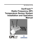
FIG. 10 is a diagram showing an example of a signal
55
out through the pairs of control signal lines 113 and 114.
FIG. 4 is a block diagram showing examples of spe
ci?c circuits of the remote controller 20, the indoor
electronic controller 5 and the outdoor electronic con
troller 15 in FIG. 3. In FIG. 4, reference characters
20A, 5A and 15A and 20B, 5B and 15B designate the
remote controller, the indoor electronic controller and
connecting terminals of the pairs of control signal lines
the outdoor electronic controller in FIG. 4;
60 113 and 114, respectively. 20C and 5C are full-wave
FIG. 11 is a diagram showing the arrangement of
recti?ers 20D, 5D and 15D are ?lters, 20E, 5E and 15E
data in transmitting data according to a control system
and 20G, 56 and 156 designate direct current blocking
according to the invention;
circuits each constituted by an insulating transformer
FIG. 12 is an explanatory diagram showing a proce
having primary and secondary coils, a photo-coupler or
dure of data transmission; and
65 a high-pass ?lter, 20F, 5F and 15F are transmitters,
FIG. 13 is a flow chart and timing diagram indicating
20H, 5H and 15H receivers, 201, 51 and 151 microcom
operations of microcomputers of controllers in the cir
puters, 20J, SJ and 151 clock circuits, 20K an operation
key input circuit, 20L a display unit for displaying the
cuits of FIG. 4.
(or a control signal) transmitted mutually between the
5
4,526,010
“on” and “off’ states of the power source or a tempera
ture set for a room, 5K and 15K sensor and switch input
6
connecting terminals 5B, 5A and 15A, 15B. The lines
can be connected in other manners.
circuits, 5L and 15L, control output circuits, 15M a DC
The operation of the circuits of the air conditioner, as
source unit composed of an AC power transformer, a
recti?er circuit and a constant voltage control circuit,
and V0 designates a DC source.
shown in FIG. 4, will now be described.
The microcomputers 20I, SI and 151 are driven by the
Each of the microcomputers 20I, SI and 151 may be
of a type TMS 1000 integrated circuit manufactured by
Texas Instruments Co. or an 8085AIC type manufac
tured by INTEL Co. The arrangement and operation of 10
such a microcomputer are described in the user’s man
ual “MSG-85 TM User’s Manual” (January I978) pub
lished by INTEL Co.
An on-off switch 21 for starting and stopping the air
conditioner and a room temperature setting unit 22 for
setting a room temperature to a desired value are con
clock circuits 20], SJ and 15] including ceramic oscilla
tion elements. The operation thereof is effected with
inputs from the operation key input circuit 20 and the
sensor and switch input circuits 5K and 15K, the out
puts to the display unit 20L and the control output
circuits 5L and 15L and the transmitting and receiving
signals of the transmitters 20F, 5F and 15F and the
receivers 20H, 5H and 15H (i.e. the control signals). In
this case, a tone burst signal (FIG. 10) modulated with
a 50 KHz signal is employed as the control signal.
The DC voltage of the DC source unit 15M is applied
to the control signal lines 113 and 114 through the filter
15D. However, it is not applied to the inputs and out
The sensor and switch input circuit 5K operates to
puts of the transmitters 20F, 5F and 15F and the receiv
receive temperature signals from the sensors 7 and 8 in
FIG. 3 and to receive on/off data from the switch 9 for 20 ers 20H, 5H and 15H as it is blocked by the DC block
ing circuits 20E, 5E and 15B and 20G, 5G and 15G. The
detecting whether or not current is ?owing for operat
DC voltage V0 is applied through the control signal
ing the motor 4.
lines 113 and 114 and the connecting terminals 20A, 5A,
In the control output circuit 5L, the output is applied
20B and 5B to the electronic circuits in the remote
to a relay coil to turn open and close the relay contacts
thereof to control thereby the operation of the fan 25 controller 20 and the indoor electronic controller. In
this connection, the connecting terminals 20A and 5A
motor 4 as shown in FIG. 4.
and 20B and 5B are non~poliarized because of the provi
The sensor and switch input circuit 15 operates to
sion of the full-wave recti?ers 20C and 5C. The trans
receive temperature signals from the sensors 17 and 18
mitting and receiving signals are removed by the ?lters
in FIG. 3 and to receive on/off data from a high voltage
20D
and 5D. If necessary, the DC voltage is applied
or overcurrent detecting switch 19 for detecting
after being made into a constant voltage.
whether or not the air conditioner is operating nor
The remote controller 20 is used to control the indoor
mally.
and outdoor electronic controllers 5 and 15 (or the
The output of the control output circuit 15L is ap
indoor and outdoor units 1 and 10) at a distance. The
plied to two relay coils, as seen in FIG. 4, so that the
microcomputer 201 is operated according to the input
operations of the fan motor 13 and the compressor 14
which is set by the operation key input circuit 20K.
are controlled according to the on-off operations of the
When the input set by the operation key input circuit 20
nected to the operation key input circuit 20K.
relay contacts.
Each of the receivers 20H, 5H and 15H may be a type
XR-567 integrated circuit manufactured by EXAR Co.
The arrangement and operation of the receiver are
described in a publication entitled “Phase-Locked Loop
Data Book” (November 1979) published by that com
pany.
is changed, or when a predetermined period of time has
elapsed after an input change, for instance, when a per
iod of time set by a timer (not shown) has elapsed, the
microcomputer 20I outputs data to the transmitter 20F.
The data is modulated with a 50 KHz signal to produce
the tone burst signal. The tone burst signal, after being
ampli?ed, is applied through the DC blocking circuit
In the transmitters 20F, 5F and 15F, the digital sig 45 20B and the connecting terminals 20A and 20B to the
nal’s high level is modulated with a high frequency
control signal lines 113. The data is arranged, as shown
transformer (not shown) so that it can be properly re
ceived by the receiver.
The above-described pairs of control signal lines 113
and 114 can be connected in various manners as shown 50
in FIGS. 5 through 9. In these ?gures, reference nu
meral 115 designates a pair of control signal lines which,
instead of one pair of control signal lines 113 and 114,
are connected between the remote controller 20 and the
in FIG. 11, to include a start bit (1 bit) modulated with
a frequency of 41.7 KHz followed by address bits (2
bits) for specifying an address at a signal destination,
and data bits (a predetermined number of bits).
As an example, if the address bits specify the mi
crocomputer 5I in the indoor electronic controller 5,
the transmitting signal received through the control
signal lines 113 and the connecting terminals 5A and 5B,
i.e. the receiving signal of the indoor electronic control
ler 5, is applied to the receiver 5H through the full-wave
outdoor electronic controller 15 (or the outdoor unit 55
100). More speci?cally, the control signal lines are con
nected between the connecting terminals 20A, 20B and
recti?er 5C after the DC voltage component has been
5A, 5B and between the connecting terminals 5A, 5B
removed by the DC blocking circuit 5G. In the receiver
and 15A, 15B in FIG. 5. In FIG. 6, the lines are con
5H, the signal is demodulated by a tone decoder imple
nected between the connecting terminal 20A, 20B and 60 mented, for instance, with a PLL phase synchronization
15A, 15B and between the connecting terminals 15A,
IC.
15B and 5A, 5B. In FIG. 7, the lines are connected
The output of the receiver 5H is applied to the mi
between the connecting terminals 20A, 20B and 5A,
crocomputer 5I. In the microcomputer SI, the levels
15B. In FIG. 8, the lines are connected between the
“1” and “0” of the data bits of the above-described data
connecting terminals 20A, 20B and 15B, 5B and be 65 are inverted, and the start bit and the address bits are
tween the connecting terminals 5A, 5B and 15B, 15A.
added to the data bits thus inverted to provide new data
In FIG. 9, the lines are connected between the connect
ing terminals 20A, 20B and 5B, 5A and between the
which is returned to the microcomputer 20I in the re
mote controller 20. In the remote controller 20, the data
7
4,526,010
thus returned is compared with the original data trans
mitted in response to which a l-bit signal is produced
indicating that signal transmission and reception should
be ended or signal transmission should be carried out
again. Each time the microcomputer 5I receives the
l-bit signal, one data transmission and reception opera
tion is completed. In this manner, the microcomputer 5I
supplies an output signal, for instance, to rotate or stop
the fan motor 4 (of. FIG. 3).
In the case also where the microcomputer SI of the
indoor electronic controller 5 or the microcomputer 15I
of the outdoor electronic controller 15 operates as the
8
and relays are used to control the inputs and outputs of
these units. Accordingly, the transmission signals are
liable to be adversely affected by noise from the power
lines, switches and relays, as a result of which erroneous
signals might be transmitted between the units. In order
to eliminate this dif?culty, it is necessary to employ
error control at the time of signal transmission. For this
purpose, an inversion return comparison system may be
employed in the invention. This system will be de
scribed.
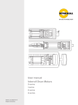
In this system, the transmission data is provided ac
cording to a modulation system as shown in FIG. 10.
signal transmitting side, the operation is similar to that
The transmission data is composed of a start bit (ST),
described above.
address bits (AD1, ADZ) for identifying the signal trans
mitting unit and the signal receiving unit, and data bits
As described above, according to the invention, wir
ing connections between the indoor unit 1 (the indoor
electronic controller 5), the outdoor unit 10 (the out
door electronic controller 15) and the remote controller
20 are achieved with the pairs of control signal lines 113
and 114 only. Suitable cables for the control signal lines
113 and 114 are readily available and the Wiring can be
readily and correctly achieved. The use of such control
signal lines is effective in that it is easy to insert them
into a conduit tube when it is required to bury them in
(DTl-DTn) which are obtained by encoding the con
trol signal and air conditioning data, as described above
with reference to FIG. 11.
FIG. 12 is an explanatory diagram illustrating a pro
cedure of transmitting data from the unit 5 to the unit
15. The unit 5 transmits the start bit (ST), the address
bits (AD) representative of the signal transmission to
the unit 15 from the unit 5 and the data bits (DT). Upon
reception of thiisignal, the unit 15 returns to the unit 5
the wall of the room or house. Furthermore, the use of 25 the data bits (DT) which are obtained by inverting the
levels “1” and “0” of the data bits (DT) received, to
the control signal lines does not detract from appear
gether with the start bit and address bits (E) indicat
ance of the room or house.
ing signal transmission to theu_nit 5 from the unit 15. If,
The embodiment of the invention shown in FIG. 4
in this case, the address bits (AD) are so set as to be the
has the following additional effects:
complement of “l” with respect to the address bits
(a) Since the connecting terminals 20A, 5A and 15A
(AD), the return data can be obtained by inverting the
and the connecting terminals 20B, 5B and 15B are non
levels “1” and “0” of all the bits except for the start bit.
polarized, no polarity wiring error can occur.
In this manner, data inversion can be readily achieved.
(b) As wiring of the pairs of control signal lines 113
Then, in the unit 5, the returned data and the original
and 114 between the connecting terminals 20A, 5A and
data transmitted therefrom are subjected to exclusive
15A and the connecting terminals 20B, 5B and 15B can
the remote controller 20 can be moved near the outdoor
logical addition to check whether or not the transmis
sion has been carried out correctly. A con?rmation
signal C is transmitted to the unit 15 to inform the unit
15 of the comparison result, i.e. coincidence or non
coincidence. In the case of coincidence, the unit 5 trans
unit 10 (the outdoor electronic controller 15) for rewir
mits a coincidence signal to the unit 15 in response to
be carried out in various combinations as shown in
FIGS. 5 through 9, the degrees of freedom in the instal
lation position of the remote controller are large. There
fore, during inspection and maintenance for instance,
which the unit 15 carries out the control operation
according to the data which has been previously re
ceived. On the other hand, in the case of non-coinci
ted and received without increasing the number of con 45 dence, the unit 5 transmits a non-coincidence signal to
the unit 15 and then transmits data again. When the unit
trol signal lines 113 and 114.
15 receives the non-coincidence signal, the previously
(d) As direct current is supplied to the remote con
received data is eliminated from the unit 15 and the unit
troller 20 from the DC source unit 15M of the indoor or
15 is maintained in the previous state until data is trans
outdoor electronic controller 5 or 15, it is unnecessary
mitted thereto from the unit 5.
to provide a power source for the remote controller 20
If the data transmission error is present repeatedly
thereby permitting miniaturization of the remote con
more than a predetermined number of times, there may
troller 20. In this case, the pairs of signal control lines
ing or to test the mutual operation thereof with ease and
with high accuracy.
(0) Many pieces of information (data) can be transmit
113 and 114 are used to feed direct current to the remote
be a problem such as a short-circuit or breakage of the
controller 20. However, it is unnecessary to increase the
signal lines. In this case, the air conditioner is stopped,
maximum voltage rating of these lines as the signal
and, for instance, a lamp is turned on to inform the user
of the occurrence of trouble.
The inversion return comparison system has been
described with respect to the units 5 and 15. However,
control lines may be of a type used for ordinary low
voltage wiring.
(e) It can be readily detected by periodic signal trans
mission and reception between the microcomputers 20I,
it is similarly applicable to other combinations of the
SI and 151 whether or not the pairs of control signal 60 units including the remote controller.
As is apparent from the above description, in the
lines 113 and 114 are short-circuited or broken.
inversion return comparison system of the invention, it
A counter-measure against noise which may affect
is unnecessary to add error detection bits to the trans
the control signal lines 113 and 114 will now be de-v
mitting and receiving data, and the error check can be
scribed. The control signals and the air conditioning
data are transmitted between the units 1, 10 and 20 65 achieved merely by calculating the exclusive logical
sum of the data. Thus, the procedure is simple, and yet
through the lines 113 and 114. In an air conditioner of
the reliability of data transmission is very high. Further
this type, the lines 113 and 114 are usually installed
more, the system is advantageous in that the inversion
adjacent to the power lines 101 and 102, and switches
4,526,010
9
.
operation can be simpli?ed by setting the address bits as
10
remote controller unit each comprise control means
requiring DC power, and in which one of said indoor
unit and outdoor unit comprises a DC source device for
supplying DC power to each of said control means, the
electric power of said DC source device being suppliedv
through said two-wire connection to the other of said
indoor and outdoor units and to said remote controller
described above. As the transmission data and the in
verted return data use the same format, the data trans
mission and the data inversion and return operations can
be incorporated into the same procedure. In general, the
air conditioner of this type employs an ordinary 4-bit,
l-chip microcomputer the program memory capacity of
which is usually 1,000 to 2,000 bytes. In order to im
prove comfort and security and to economically use
unit.
4. The separated-unit type air conditioner as claimed
energy, the data transmitting and receiving program’s
capacity is greatly limited. Thus, if the transmission
in claim 3 in which said remote controller unit and said
other of said indoor unit and outdoor unit in which said
DC source device is not provided each comprise cir
cuits for non-polarizing signals received over said two
wire connection.
5. The separated-unit type air conditioner as claimed
in claim 4 in which each of said circuits for non-polariz
error control according to the inversion return compar
ison system having the above-described effects or mer
its is applied to the air conditioner as described above, a
two-wire system separated-unit type air conditioner
control system can be implemented without a corre
sponding lowering in the comfort level afforded by the
system.
ing said signals comprises a full-wave recti?er circuit.
6..The separated-unit type air conditioner as claimed
In FIG. 13 is a flow chart and timing diagram show
in
claim 3 further comprising direct current blocking
ing in detail the operations of the microcomputer 201, SI 20
means provided between said two-wire connection and
and 15I of the controllers 20, 5 and 15, respectively, as
each of said ?rst and second means.
described above. To program the microcomputers 20I,
7. The separated-unit type air conditioner as claimed
in claim 3 in which said units which receive DC power
form of the steps of course being determined by the 25 from said DC source device each comprise ?lter cir
cuits for receiving DC power from said two-wire con
particular type of microcomputer chosen. Program
nection and providing said DC power to said control
steps of a conventional nature may further be included
means.
if desired and the invention is not limited to the use of
8. The separated-unit type air conditioner as claimed
any particular sets of program instructions.
in
claim 1 in which said ?rst means carries data trans
What is claimed is:
30
mission again when said data has not been received
1. A separated-unit type air conditioner having an
SI and 151, the information from the flow chart can be
translated directly into program steps with the precise
correctly, and when incorrect reception of data is de
indoor unit, an outdoor unit and a remote controller
tected a predetermined number of times, operates to
unit which are provided at three different positions, the
stop operation of said air conditioner and to inform a
improvement comprising communication means for
transmitting information between any two of said units 35 user of an abnormal condition.
9. A separated-unit type air conditioner as claimed in
over a two-wire connection, said communication means
claim 1, wherein each of said indoor unit, outdoor unit
comprising:
and remote controller unit include both said ?rst means
?rst means at a ?rst of said any two units for transmit
and said second means.
ting binary data onto said two-wire connection
together with a binary second address identifying
10. A separated-unit type air conditioner as claimed
in claim 9, said air conditioner including a temperature
sensor for providing a temperature signal representing
sensed temperature, wherein: said indoor unit includes
data transmission to a second of said any two units;
second means at said second unit for inverting said
second address to form a ?rst address identifying
data transmission to said ?rst unit, for inverting
an indoor heat exchanger, an air blowing motor, an air
said data to form inverted data and for transmitting 45 blowing fan and a ?rst of said control means for receiv
said ?rst address and inverted data onto said two
ing said temperature signal and providing a control
wire connection, said ?rst means comparing said
output to drive said air blowing motor; said outdoor
data and inverted data to determine if said data was
unit includes an outdoor heat exchanger, an air blowing
received correctly at said second unit.
motor, an air blowing fan, a compressor and a second of
2. The separated-um type air conditioner as claimed 50 said control means for receiving said temperature signal
in claim 1 in which each of said ?rst and second means
and providing control outputs to drive said air blowing
comprises a modulator for high frequency modulating
motor and compressor; and said remote controller unit
wherein said binary data, inverted data and ?rst and
includes a power switch, room temperature setting
second addresses are transmitted in the form of a high
means and a third of said control means for receiving
frequency modulated signal on said two-wire connec 55 signals from said power switch and room temperature
tion.
setting means to provide predetermined control out
3. The separated-unit type air conditioner as claimed
puts.
*
*
*
*
*
in claim 1, wherein said indoor unit, outdoor unit and
60
65