1
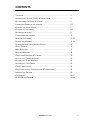
ALLEN&HEATH
GL2200
Dual Function Audio Mixing Console
USER GUIDE
PUBLICATION: AP3388
LIMITED ONE YEAR WARRANTY
This product has been manufactured in the UK by ALLEN & HEATH and
is warranted to be free from defects in materials or workmanship for
period of one year from the date of purchase by the original owner.
To ensure a high level of performance and reliability for which this
equipment has been designed and manufactured, read this User Guide
before operating.
In the event of a failure, notify and return the defective unit to ALLEN &
HEATH or its authorised agent as soon as possible for repair under
warranty subject to the following conditions:
CONDITIONS OF WARRANTY
1. The equipment has been installed and operated in accordance with
the instructions in this User Guide.
2. The equipment has not been subject to misuse either intended or
accidental, neglect, or alteration other than as described in the User
Guide or Service Manual, or approved by ALLEN & HEATH.
3. Any necessary adjustment, alteration or repair has been carried out by
ALLEN & HEATH or its authorised agent.
4. The defective unit is to be returned carriage prepaid to ALLEN &
HEATH or its authorised agent with proof of purchase.
5. Units returned should be packed to avoid transit damage.
These terms of warranty apply to UK sales. In other territories the terms
may vary according to legal requirements. Check with your ALLEN &
HEATH agent for any additional warranty which may apply.
GL2200 User Guide AP3388 Issue 4. Copyright © 2001 Allen & Heath Limited. All rights reserved
This product complies with the European Electromagnetic Compatibility
Directives 89/336/EEC & 92/31EEC and the European Low Voltage Directives
73/23/EEC & 93/68 EEC
MANUFACTURED IN ENGLAND BY:
Allen & Heath Limited
Kernick Industrial Estate
Penryn, Cornwall, TR10 9LU. UK
http://www.allen-heath.com
ALLEN&HEATH
CONTENTS
CONTENTS .......................................................................................................3
INTRODUCTION, SERVICE, SAFETY & PRECAUTIONS ............................................4
KEY FEATURES, THE RANGE & OPTIONS.............................................................5
CONNECTING POWER TO THE CONSOLE .............................................................6-7
EARTHING THE AUDIO SYSTEM ...........................................................................7
PLUGGING UP THE CABLES.................................................................................8-9
ADJUSTING THE LEVELS .....................................................................................9
FLIGHTCASING THE CONSOLE.............................................................................10
MONO INPUT CHANNEL .....................................................................................11-12
STEREO INPUT CHANNEL ...................................................................................13-14
STEREO RETURNS & AUX MASTER OUTPUTS ....................................................15
GROUP OUTPUTS .............................................................................................16
MODE SWITCHING .............................................................................................17
MASTER & MONITOR .........................................................................................18
OSCILLATOR/PINK NOISE & TALKBACK ...............................................................19
APPLICATION – FRONT OF HOUSE .....................................................................20
APPLICATION – STAGE MONITOR .......................................................................21
APPLICATION – DUAL MODE .............................................................................22
FRONT PANEL LAYOUT ......................................................................................23
REAR PANEL LAYOUT / SPECIFICATIONS & CONNECTIONS ...................................24
INTERNAL LINK OPTIONS ...................................................................................25
CUE SHEETS ....................................................................................................26-27
GL2200 BLOCK DIAGRAM .................................................................................COVER
GL2200 USER GUIDE
3
INTRODUCTION
The GL2200 continues ALLEN & HEATH’s commitment to provide high quality audio mixing consoles
engineered to meet the exacting requirements of today’s audio business. It brings you the latest in
high performance technology and offers the reassurance of over two decades of console manufacture
and customer support.
This user guide presents a quick reference to the function, application and installation of the GL2200.
We recommend that you read this guide fully before operating the console For further information on
the basic principles of audio system engineering please refer to one of the specialist publications
available from bookshops and audio equipment dealers.
Whilst we believe the information in this guide to be reliable we do not assume responsibility for any
inaccuracies. We also reserve the right to make changes in the interest of further product
development.
SERVICE AND TECHNICAL SUPPORT
Under normal conditions the GL2200 does not require user maintenance or internal calibration. Any
service work required should be carried out by qualified service personnel only.
We are able to offer further product support through our world-wide network of approved dealers and
service agents. You can also access our Web site on the internet for information on our product
range, assistance with your technical queries or simply to chat about audio matters. To help us
provide the most efficient service please keep a record of the console serial number, and date and
place of purchase to be quoted in any communication regarding this product.
SAFETY WARNING!
Mains electricity is dangerous and can kill. Mains voltage
is present within the console power supply.
Do not remove the power supply cover with mains
electricity connected. To ensure your safety, mains earth
is connected to the chassis through the power lead. Do
not remove this mains earth connection.
To avoid the risk of fire, replace the mains fuse only with
the correct value and type as indicated on the power
supply unit.
GENERAL PRECAUTIONS
Your GL2200 is ruggedly constructed to give many years of reliable operation. However, you will
extend the life of the console and preserve its cosmetics by applying these simple common sense
precautions.
•
Avoid storing or using the mixing console in conditions of excessive heat or cold, or in positions
where it is likely to be subject to vibration, dust, dirt or moisture.
•
Do not use any liquids to clean the control surface of the console, a soft dry brush or dry lint-free
cloth is ideal.
•
Use only water or ethyl alcohol to clean the trim and scribble strips. Other solvents may cause
damage to paint or plastic parts.
•
The faders, switches and potentiometers are lubricated for life. The use of electrical lubricants on
these parts is not recommended.
•
Avoid using the console close to strong sources of electromagnetic radiation (e.g. video monitors,
high power electric cabling): this may cause degradation of the audio quality due to induced
voltages in connecting leads and chassis. For the same reason, always site any external power
supply away from the unit.
4
GL2200 USER GUIDE
KEY FEATURES OF THE GL2200
The ALLEN & HEATH GL2200 offers the user the versatility to quickly adapt to the exacting demands
of live sound engineering today. The GL2200 is developed from the very successful GL2000 console,
which included mode switching to quickly convert the console from Front-of-House to On-stage
Monitor operation. In addition, the GL2200 includes 4 subgroups, 6 independent aux sends, stereo
mic/line channels, pink noise generator, 1kHz oscillator and lots more. It is built on the established
tradition of innovative British design and manufacture. The GL2200 is equally suited to home and
studio recording. Features include:
•
FOH/stage-monitor dual functionality
•
4 groups, 6 auxes
•
Groups, L, R and Mono outputs on balanced XLR
•
12, 16, 24 and 32 channel frames
•
2 stereo line channels with mic capability
•
2 stereo returns with mutes, faders, EQ and Aux sends
•
Mutes on Groups and L-R
•
Channel direct outs
•
2-track send and return
•
4-band EQ with swept mids and in/out switch
•
Input metering on each channel
•
Phantom Power 48V, switchable on each channel
•
Inserts on all mono inputs
•
Inserts on Groups (auxes) and L-R outs
•
Comprehensive AFL/PFL monitoring
•
Pink noise generator for speaker setup
•
Oscillator for equipment line up
•
Talkback facility
•
High-performance internal power supply with universal mains input voltage
•
Built-in combiner to add external backup power supply
•
Console lamp connector
•
Sys-linkTM expandability
•
Rugged build quality
The console is constructed using zinc plated steel panels and 1.6mm thick metal side plates.
Individual circuit board assemblies are accessible by removal of the steel base. A durable soft front
armrest is provided for comfort. A channel top write-on strip is provided for channel marking. High
quality reliable parts are used throughout. High performance op-amp and discrete circuits are used to
ensure low noise and sonic purity. The internal power supply is a low noise switch mode unit that can
be linked with an external DC power supply.
THE RANGE
12, 16, 24 and 32 channel models
GL2200-412 10 mono, 2 stereo, 4 groups, 6 aux, 2 stereo returns, L, R, Mono sum
GL2200-416 14 mono, 2 stereo, 4 groups, 6 aux, 2 stereo returns, L, R, Mono sum
GL2200-424 22 mono, 2 stereo, 4 groups, 6 aux, 2 stereo returns, L, R, Mono sum
GL2200-432 30 mono, 2 stereo, 4 groups, 6 aux, 2 stereo returns, L, R, Mono sum
OPTIONS
GL2200-SL1
RPS9
Sys-link buss expander, one kit per console
2U rack mount power supply for backup
GL2200 USER GUIDE
5
CONNECTING POWER TO THE CONSOLE
Refer to the SAFETY WARNING on page 4 of this User Guide. Read and understand the warnings
and instructions printed on the rear panel of the console and printed here.
Ensure adequate ventilation around the console. Do not cover the
console or position it on soft furnishings during operation.
The console must be connected to 0V ground by either the a.c.
mains input cable or by the EXTERNAL DC IN cable.
CAUTION: FOR CONTINUED PROTECTION AGAINST RISK OF FIRE REPLACE FUSE
WITH SAME TYPE AND RATING.
ATTENTION: REMPLACER LE FUSIBLE AVEC UN DES MEMES CARACTERISTIQUES.
WARNING: DISCONNECT SUPPLY BEFORE CHANGING FUSE.
ATTENTION: COUPER L'ALIMENTATION AVANT DE CHANGER LE FUSIBLE.
100 - 240V~
EXTERNAL SUPPLY
ACTIVE
INTERNAL SUPPLY
ACTIVE
T1A 250V 20mm
WARNING - THIS APPARATUS MUST BE EARTHED.
SUPPLY VOLTAGE RANGE:
100 - 240V.AC
47-63Hz ~ 60W MAX
WARNING: TO REDUC
SEE INSTA
DO NOT OB
NO USER S
The GL2200 console can be powered from either the internal power supply, from an external
DC supply such as the Allen & Heath RPS9, or both together. The LED indicators on the rear
panel illuminate to indicate which supply is active.
Normally the internal power supply will be used to power the console by the standard 3 pin IEC
mains input connector. A mains cable with moulded mains plug suitable for the local supply is
supplied. Check that the correct mains lead with moulded plug has been supplied with your
console. Ensure that the IEC mains plug is fully inserted into the rear panel socket before
switching on.
POWER SUPPLY
The internal power supply for the GL2200 is a switch mode supply and will operate from a wide
range of mains input voltages. It produces the DC voltages required by the console. Before
switching on your console, check that the ac mains fuse is of the correct type and rating. This is
clearly marked on the rear panel of the console. Do not replace the fuse with any other type, as
this could become a safety hazard and will void the warranty.
AC~ mains input voltage
Fuse value
100 - 230V ±10%
T 1A 250V 20mm
CAUTION: For continued protection against the risk of fire, replace
fuse only with the correct type and value.
The console power supply unit contains no user serviceable parts.
Do not remove the cover. Refer servicing to qualified service
personnel only.
6
GL2200 USER GUIDE
An external DC supply may be used instead of, or together with the internal supply. Use only
recommended Allen & Heath power supplies or a supply approved by Allen & Heath. The use of
alternative supplies is not recommended and may cause damage.
The pin connections for the EXTERNAL DC IN connector are specified below:
Pin
Voltage
Current
1
-16V
1.5A
2
Audio 0V
3
Chassis 0V
4
+16V
1.5A
5
+48V
0.1A
In the absence of an active 100V to 230V a.c. mains supply, the GL2200 will automatically switch over
to the external DC supply unit if connected.
Always turn connected power amplifiers down or off before switching the console on or off.
In the event of an electrical storm, or large mains voltage
fluctuations, immediately switch off and disconnect all power to the
console.
EARTHING THE AUDIO SYSTEM
The console chassis is connected to mains earth via the power cable. Audio 0V is connected
internally to the chassis and therefore mains earth. In this way all signal returns and connector shields
are connected to mains earth at the console.
To ensure safety, do not remove the earth connection from the AC
mains plug or from EXTERNAL DC IN cable.
For best performance it is important that the earth system is solid, clean and noise-free. To prevent
mains-borne and external interference pickup from lighting equipment, motors and other mains
powered equipment it is recommended that a separate ‘clean’ mains distribution outlet is used for the
audio system.
All signal cables should have their screens connected to earth at the connector. If earth (ground) loop
problems result in audible hum or buzz then disconnect the cable screen connection at one end,
usually the destination end. This may be done within the cable plug or by operating the ‘ground lift’
switch if available on the connected equipment. Many DI boxes and power amplifiers include this
facility.
GL2200 USER GUIDE
7
PLUGGING UP THE CABLES
The GL2200 uses professional grade 3-pin XLR, 1/4" TRS jack and RCA PHONO sockets.
Where possible use balanced connections to prevent noise and interference pickup especially
on long cable runs. Avoid running audio cables next to AC mains, computer or lighting cables,
near thyristor dimmer units or power supplies etc. The use of low impedance sources such as
good quality microphones of 200 ohms or less significantly reduces interference pickup. Many
problems can be avoided by taking time to check that all cables are correctly wired. Avoid
reversing + and - on balanced connections as this will result in out of phase signals (reverse
polarity) causing signal cancellation effects. This situation is particularly common in multimicrophone mixing. Use professional quality cable and carefully soldered connections. The
following wiring convention is used:
XLR
¼” TRS jack
Pin 1
0V earth shield
Tip
+ / hot / signal / left / send
Pin 2
+ / hot / signal
Ring
- / cold / 0V / right / return
Pin 3
- / cold
Sleeve
0V earth shield
CABLE WIRING
Tip
1
OUTPUT
Ring
Sleeve
Tip
Ring
BALANCED
Sleeve
3
2
CONSOLE
CONNECTIONS
3-PIN XLR FEMALE PLUG
TWIN SCREENED CABLE
2
INPUT
3
1
¼" 3-POLE (STEREO) JACK PLUG
3-PIN XLR MALE PLUG
Tip
1
OUTPUT
3
2
Link
Sleeve
Sleeve
Tip
UNBALANCED
3-PIN XLR FEMALE PLUG
SINGLE SCREENED CABLE
CONSOLE
CONNECTIONS
2
INPUT
3
1
¼" 2-POLE (MONO) JACK PLUG
3-PIN XLR MALE PLUG
Sleeve
Ring
CONSOLE
CONNECTIONS
Tip
Ring
SINGLE SCREENED CABLE
UNBALANCED
Tip
Sleeve
OUTPUT
Link
INPUT
RCA PHONO PLUG
¼" 3-POLE (STEREO) JACK PLUG
To connect an unbalanced source to a balanced console input, link the cold input (XLR pin 3 or
jack ring) to 0V earth (pin 1 or jack sleeve) at the console. To connect a balanced console
output to an unbalanced destination link the cold output to 0V earth at the console.
Deselect input channel +48V when inputs are connected to non-phantom
powered, mic, line or unbalanced sources.
8
GL2200 USER GUIDE
CONNECTING CHANNEL INPUTS
Both microphone and line sources such as keyboards, replay devices and effects processors
can be plugged into either the jack or XLR input for convenience. The channel accepts a wide
70dB range of source levels. The balanced 3-wire input provides the best immunity to
interference pickup on long cable runs.
CONNECTING TO INSERTS
You do not need to plug anything into the insert socket for normal operation. You may, however
wish to insert a signal processor such as a compressor/limiter or noise gate into the signal path
to prevent excessive peaks or to cut down source noise. The insert lets you do this by breaking
the signal path after the input pre-amp and before the EQ in the channel input or before the
fader in the Group and L-R section. Use a Y-lead or suitable TRS jack lead to connect to the
external processor. The insert operates at 0dBu line level in the channel input and –2dBu in the
Group and L-R section. Adjust the processor input and output levels for optimum signal level.
CHANNEL DIRECT OUTPUTS
The channel direct output taps the signal off post-fader (pre-fader if the internal link option is
changed) for connection to external processing or recording equipment. This is ideal for
multitrack recording during a live performance. Here each channel can be recorded on a
separate track for mixdown later. The output is impedance balanced on TRS jack. This means
that you get the benefit of interference immunity when connecting to outboard equipment with
balanced inputs. You can, of course, also connect to unbalanced equipment. The signal
operates at nominal 0dBu line level.
ADJUSTING THE LEVELS
For best performance it is important that the connected source signals are matched to the “normal
operating level” of the console. Similarly the console outputs should be correctly matched to the
operating levels of the connected amplifiers and destination equipment. If too high, the signal peaks
will be clipped resulting in a harsh distorted sound, and if too low, the signal-to-noise ratio is reduced
resulting in excessive background hiss.
For best results, operate the console with the meters averaging ‘0’ or just below and allowing the
loudest passages and occasional peaks into the ‘yellow’. Reduce the gain if the peak indicators flash
(red). The GL2200 provides +4dBu output level at the XLR outputs for a meter reading of 0VU. It is
advisable to adjust the power amplifier input gain or fit an attenuator pad if normal console operation
results in an output level too high for the connected amplifier. Normal operation should give rise to
fader levels around the ‘0’ mark.
The GL2200 has an advanced PFL (pre-fade listen) / AFL (after-fader listen) and channel metering
system to let you listen to and check the level of signals at different points in the signal path without
affecting the main outputs. Use the channel PFL switches to set up the input GAIN controls to read an
average ‘0’ (yellow LED). Signal activity is always shown on the channel meters regardless of fader
position. The green ‘SIG’ LED lights at -20dBu to indicate signal presence, the yellow ‘0’ LED
indicates normal level, and the red ‘PEAK’ LED warns of potential overload 5dB before clipping.
GL2200 USER GUIDE
9
FLIGHTCASING THE CONSOLE
If the console is to be regularly moved we recommend that it is installed in a foam-lined flightcase.
At all times avoid applying excessive force to any knobs, switches or connectors.
Dimensions for flightcasing the console are shown below:
DIMENSIONS
Unpacked
Packed
Width
depth
height
weight(kg)
Width
depth
height
weight(kg)
GL2200-412 ........................548 ............ 572 ............ 155 ............ 16.....................700 ............ 750 ............ 280 ............ 20
GL2200-416 ........................668 ............ 572 ............ 155 ............ 18.....................815 ............ 750 ............ 280 ............ 23
GL2200-424 ........................920 ............ 572 ............ 155 ............ 24.....................1065 .......... 750 ............ 280 ............ 29
GL2200-432 ........................1160 .......... 572 ............ 155 ............ 30.....................1325 .......... 750 ............ 280 ............ 35
RPS9 power supply ............483 ............ 140 ............ 96 ............. 6......................540 ............ 270 ............ 180 ............ 8
10
GL2200 USER GUIDE
MONO INPUT CHANNEL
The mono input channel is designed using a very high quality analogue signal path
to ensure absolute sonic purity for microphone or line level sources.
48V
1
Ø
PAD
-30dB
0
GAIN
40
30
MIC INPUTS Plug a microphone source into the XLR input. If you
leave the jack input unplugged then the PAD (LINE) switch becomes a
30dB pad for the microphone. This lets you use the XLR input for high
output microphones, or for line level sources.
LINE INPUTS Plug a line level source into either the XLR or the TRS
jack input. If you use the XLR input make sure that you do not plug
anything into the jack input, and that you press the PAD (LINE) switch.
If you use the TRS jack input make sure that you press the PAD (LINE)
switch. The jack input is only selected with this switch pressed.
50
PAD
- 10 20
60 30
100Hz
0
HF
12kHz
-15
+ 15
3kHz
500Hz
15kHz
0
MF1
-15
+ 15
250Hz
35Hz
1kHz
0
MF2
-15
48V selects +48V to the XLR input for microphones that require phantom power.
IMPORTANT NOTE : Switch off channel +48V when non-phantom powered
mic, line or unbalanced sources are to be used with the inputs.
+ 15
0
LF
60Hz
-15
+ 15
EQ IN
AUX
1
φ
reverses the POLARITY of the input source to correct the problems often
encountered in microphone placement, or due to incorrectly wired cables (pin 3
hot instead of pin 2). May also helpful in reducing acoustic feedback between
closely positioned loudspeakers and mics in live sound mixing.
PAD (LINE) selects the line level jack input when pressed or becomes a 30dB pad
for the XLR input when no jack is plugged in. The XLR is normalled through the
unplugged jack contacts. See MIC/LINE description above.
GAIN matches the level of the input source to the normal operating level of the
console. Adjust this to read an average ‘0dB’ on the channel meter (yellow LED).
Use the PFL system to listen to the signal and fine tune the gain.
0
OO
+6
OO
+6
OO
+6
OO
+6
AUX
2
0
AUX
3
0
AUX
4
0
PRE
AUX
5
0
OO
+6
OO
+6
AUX
6
100Hz 18dB/Octave lo-cut filter removes low frequency noise such as microphone
pops, proximity effect, stage noise and transport rumble after the pre-amp stage. It
can also be used to clean up sounds that do not have much bass content, such as
vocals and cymbals. The lo-cut filter is independent of the equaliser.
0
PRE
C
PAN
ODD
L
The 4-band EQ lets you adjust the tonal quality of the sound. The
LF (bass) bands have a shelving response, which means that
beyond the corner frequency are affected. Used with the 100Hz
can tailor the low frequency response exactly as you require.
position is detented for quick resetting.
EVEN
R
MUTE
PEAK
+6
0
10
SIG
HF (treble) and
all frequencies
lo-cut filter you
The centre flat
5
AMPL(dBr) vs FREQ(Hz)
PFL
L-R
0
10.00
5
0.0
1-2
-10.00
10
3-4
-20.00
-30.00
20
-40.00
30
OO
-50.00
-60.00
10
100
1k
10k
20k
100 Hz lo-cut filter
GL2200 USER GUIDE
HF and LF EQ
11
48V
1
Ø
PAD
-30dB
0
GAIN
The 2 mid frequency bands MF1 and MF2 can be swept across a wide frequency
range to tune into the exact frequency required; useful for getting the best out of
microphones or for tuning out troublesome feedback. The mid bands are
overlapping with a Q of 1.6 and can boost or cut in excess of +/- 15dB. The centre
flat position is detented for quick resetting.
40
30
50
PAD
- 10 20
60 30
100Hz
0
HF
12kHz
-15
+ 15
3kHz
500Hz
15kHz
0
MF1
-15
+ 15
250Hz
35Hz
1kHz
0
MF2
-15
+ 15
MF1 EQ
0
LF
60Hz
-15
+ 15
EQ IN
AUX
1
0
OO
+6
OO
+6
OO
+6
OO
+6
AUX
2
0
AUX
3
0
AUX
4
0
PRE
AUX
5
0
OO
+6
OO
+6
AUX
6
0
PRE
C
PAN
ODD
L
EVEN
R
MUTE
PEAK
+6
0
10
SIG
5
PFL
0
L-R
5
1-2
10
3-4
20
30
OO
12
MF2 EQ
Press EQ IN to switch the EQ into the signal path.
6 AUX SENDS provide feeds for foldback monitors and effects. Aux 1-4 and Aux
5-6 may be set to pre or post-fader using the PRE switch.
Monitor sends to the performers are usually set pre-fade (PRE), although some
sources such as radio mics are often set post-fade to avoid ‘dressing room’ talk
spill.
Effects sends to external signal processing equipment such as reverb and delay
effects units, are usually set post-fade so that the amount of effect (wet signal) is
always relative to the position of the fader (dry signal).
Adjust the amount of effect required for each channel using its AUX control.
The effect is returned to the mix through another channel, usually the stereo
return described later in this guide.
POST-FADE sends are post-EQ, post-mute. PRE-FADE sends are set post-EQ,
post-mute as standard. Internal link options are available to change the source of
the pre-fade sends. Refer to the internal link options section in this user guide.
Note; AUX 1-6 feed XLR outputs with inserts when the GRP/AUX REVERSE
switches are pressed in the master section.
PAN positions the channel signal within the stereo image or between L-R and the
groups when the routing switches are selected. The centre position is detented for
quick resetting.
MUTE switches the signal off when pressed regardless of fader position. Muted
channels are indicated by red LEDs. The channel meter continues to indicate prefader channel activity.
A 4 LED CHANNEL METER shows signal activity at all times. The green SIG
LED indicates signals greater than -20dBu, yellow ‘0’ and ‘+6’ represents normal
operating level, and red PEAK warns of potential overload 5dB before clipping.
Set the channel signal so that the meter averages between ‘0’ and ‘+6’. Back the
gain off if the red peak LED flashes.
Pressing PFL lets you listen to the channel pre-fader signal on headphones
without interrupting the main console outputs. The signal level is shown on the LR bargraph meters. In this way each sound can be correctly lined up and checked
at any time.
L-R, 1-2, 3-4 routing switches feed the channel signal to the L-R mix and groups
1-2, 3-4. Use the pan control to route to individual groups, i.e. left to route to L, 1,
3 and right to route to R, 2, 4. In this way subgroups may be set up in mono or
stereo to feed the main L-R mix.
A 100mm FADER provides +10dB boost above the normal ‘0’ operating level. All
post-fade aux send levels are dependent on the level of the fader.
GL2200 USER GUIDE
STEREO INPUT CHANNEL
Two stereo input channels are included as standard. Each features a 4-band
EQ, 6 aux sends and group routing. Use this channel for stereo sources such
as keyboards and two track players, or for returning additional effects
processors to the mix and monitors. A mic input is included so that you can
use the channel for additional mics when needed. The stereo line input can still
be routed to the mix while using the channel mic input.
The stereo inputs are on separate TRS jacks. For mono line sources plug into
the L/MONO jack socket only. For microphone sources plug into the XLR.
48V
12
Ø
30
20
40
50
MIC
GAIN
60dB
10
MIC TO TALK
10
0
LINE
GAIN
OO
20
LINE
TO L-R
MIC
LINE
0
HF
12kHz
-15
+ 15
0
MF1
2.5kHz
-15
+ 15
0
MF2
250Hz
-15
+ 15
0
LF
60Hz
-15
+ 15
EQ IN
AUX
1
0
OO
+6
OO
+6
OO
+6
OO
+6
AUX
2
0
AUX
3
0
AUX
4
0
MIC TO TALK
ENABLE
48V selects +48V DC to the XLR input for microphones that require phantom
power.
IMPORTANT NOTE : Switch off channel +48V when non-phantom
powered or unbalanced sources are connected to the XLR input.
φ reverses the POLARITY of the input source to correct problems often
encountered in microphone placement, or due to incorrectly wired cables (pin 3
hot instead of pin 2). May also be helpful in reducing acoustic feedback
between closely positioned loudspeakers and mics in live sound mixing.
GAIN controls for the MIC and LINE inputs let you adjust each source
independently.
LINE TO L-R routes the stereo line source direct to the L-R mix. In this way
both the mic and stereo line inputs may be used at the same time. The mic
can be routed through the stereo channel while the line input becomes an
independent source or return to the LR mix.
MIC/LINE selects either the mic XLR or the stereo line jack inputs to the
channel. When selecting LINE on the second stereo input channel, the MIC
input section is available as the source for talkback. A green LED indicator
illuminates to confirm this. The channel can be used with the stereo line input
in the normal way while the mic is independently used for talkback.
PRE
AUX
5
0
OO
+6
OO
+6
AUX
6
0
PRE
C
BAL
ODD
L
EVEN
R
MUTE
PEAK
+6
0
10
SIG
5
PFL
0
L-R
5
1-2
10
3-4
20
30
OO
STEREO
15-16
The 4-band stereo EQ lets you adjust the tonal quality of the sound. The HF
(treble) and LF (bass) bands have a shelving response, which means that all
frequencies beyond the corner frequency are affected. The 2 mid frequencies
MF1 and MF2 provide optimum control over boomy or boxy sounds (250Hz),
and can add bite or reduce harshness to keyboards, vocals etc. (2.5kHz). The
centre flat position is detented for quick resetting.
6 AUX SENDS provide feeds for foldback monitors and effects. Aux 1-4 and
Aux 5-6 may be set to pre or post-fader using the PRE switch. The left and
right stereo signals are summed to provide aux feeds in mono.
Monitor sends to the performers are usually set pre-fade (PRE), although
some sources such as radio mics are often set post-fade to avoid ‘dressing
room’ talk spill.
Effects sends to external signal processing equipment such as reverb and
delay effects units, are usually set post-fade so that the amount of effect (wet
signal) is always relative to the position of the fader (dry signal).
Adjust the amount of effect required for each channel using its AUX control.
The effect is returned to the mix through another channel, usually the stereo
return described later in this guide.
POST-FADE sends are post-EQ, post-mute. PRE-FADE sends are set postEQ, post-mute as standard. Internal link options are available to change the
source of the pre-fade sends. Refer to the internal link options section in this
user guide.
Note; AUX 1-6 feed XLR outputs with inserts when the GRP/AUX
REVERSE switches are pressed in the master section.
GL2200 USER GUIDE
13
48V
12
Ø
30
20
40
50
MIC
GAIN
60dB
10
MIC TO TALK
10
0
LINE
GAIN
OO
20
LINE
TO L-R
MIC
LINE
0
HF
12kHz
-15
+ 15
0
MF1
2.5kHz
-15
+ 15
0
MF2
250Hz
-15
+ 15
0
LF
60Hz
-15
+ 15
EQ IN
AUX
1
MIC TO TALK
ENABLE
BAL positions the channel signal within the stereo image or between L-R and
the groups when the routing switches are selected. The centre position is
detented for quick resetting.
MUTE switches the signal off when pressed regardless of fader position.
Muted channels are indicated by red LEDs. The meter continues to indicate
pre-fader channel activity.
A 4 LED CHANNEL METER shows signal activity. The green SIG LED
indicates signals greater than -20dBu, yellow ‘0’ and ‘+6’ represents normal
operating level, and red PEAK warns of potential overload 5dB before clipping.
Set the channel signal so that the meter averages between ‘0’ and ‘+6’. Back
the gain off if the red peak LED flashes.
Pressing PFL lets you listen to the channel pre-fader signal on headphones
without interrupting the main console outputs. The signal level is shown on the
L-R bargraph meters. In this way each sound can be correctly lined up and
checked at any time.
L-R, 1-2, 3-4 routing switches feed the channel signal to L-R mix and groups
1-2, 3-4. Use the pan control to route to individual groups, ie left to route to L,
1, 3 and right to route to R, 2, 4. In this way subgroups may be set up in mono
or stereo to feed the main L-R mix.
A 100mm FADER provides +10dB boost above the normal ‘0’ operating level.
All post-fade aux send levels are dependent on the level of the fader.
0
OO
+6
OO
+6
OO
+6
AUX
2
TALKBACK SIGNAL
TO OSC/TALKBACK
0
AUX
3
0
AUX
4
MIC TO TALK
ENABLE
(LAST STEREO ONLY)
GAIN
0
OO
MIC IN
+6
2= +
x2
PFL
4-BAND
EQUALISER
+
PRE
STEREO
CHANNEL
PEAK
+ 6dB
0dB
SIG
FADER
HF
AUX
5
+ 48V
0
OO
MIC/
LINE
+6
AUX
6
MF1
L
R
0
OO
+6
EQ IN
BAL
MUTE
+
MF2
L-R
1-2
POST
3-4
LF
PRE
C
BAL
ODD
L
EVEN
R
MUTE
L/MONO
LINE
LEV
POST-EQ
POST-MUTE
PRE-EQ
PRE-MUTE
+
PEAK
SUM
+6
R
0
+
INTERNAL AUX LINK OPTIONS
POST-FADE
SWITCHED
PRE-FADE
10
SIG
PRE
SUM
AUX 1
AUX 2
5
AUX 3
PFL
0
AUX 4
L-R
5
POST
PRE
AUX 5
1-2
10
3-4
AUX 6
20
POST
PRE
30
LINE TO L-R
AUX 1-6
GRP 1-4
LEFT
RIGHT
P/AFL
OO
STEREO
15-16
The stereo input diagram showing the
talkback and stereo line signal routing.
14
GL2200 USER GUIDE
STEREO RETURNS
HF
12kHz
-15
+ 15
0
LF
60Hz
-15
+ 15
AUX
1
0
OO
+6
OO
+6
AUX
2
0
BAL
L
R
ODD
EVEN
MUTE
PFL
10
L-R
1-2
5
0
5
10
20
Two stereo return inputs are provided with 2-band EQ, sends to auxes 1 & 2 and
routing to L-R mix or groups 1-2/3-4. These are normally used to return the effects
(‘wet’) signal, usually from a stereo device, to the mix. They can also be used for
additional line inputs to the mix.
A 2 band EQ provides HF and LF control with 15dB cut and boost at 12kHz and
80Hz respectively. This is often used to remove unwanted high or low frequency
noise from effects devices.
2 aux sends are provided to feed a summed left and right pre-fade post mute
signal to auxes 1 & 2. This is ideal for returning effects to the monitors without
using up valuable channel inputs.
The BAL control adjusts the balance between left and right signals, or can be used
as a pan control to route the signal to one side only by rotating fully.
MUTE switches the signal off when pressed regardless of fader position. Muted
Returns are indicated by red LEDs. Mute does affect the pre-fade aux sends.
Pressing PFL lets you listen to the channel pre-fader signal on headphones
without interrupting the main console outputs. The signal level is shown on the L-R
bargraph meters. In this way each sound can be correctly lined up and checked at
any time.
L-R/1-2 (3-4) ROUTING SWITCHES - In the up position the signal is routed to the
main L-R mix but may be returned to the corresponding pairs of subgroups for
group effects (1-2 or 3-4).
A smooth travel 60mm FADER provides precise control of the level.
30
OO
STEREO
RETURN
AUX OUTPUTS
AUX MASTERS
Each aux mix has a master level control that adjusts the output level to match external
equipment, or to trim the monitor or effects level without affecting the mix balance. Up to +10dB
of boost is available above the nominal ‘0’ position. Auxiliary outputs are on 3-wire impedance
balanced 1/4” TRS jacks.
AFL (After Fade Listen) routes the post mix signal to the console meters and headphone
monitoring to allow checks for sound quality and mix level.
AUX
1
0
OO
AUX
2
+ 10
AFL
GRP/AUX 1-2
REVERSE
0
OO
+ 10
AFL
AUX
3
0
OO
AUX
4
+ 10
AFL
0
OO
AUX
5
+ 10
AFL
GRP/AUX 3-4
REVERSE
0
OO
AUX
6
+ 10
AFL
L-R/AUX 5-6
REVERSE
0
OO
+ 10
AFL
FOH
STAGE MONITOR
If MODE SWITCHING aux/groups reverse is in operation, aux master level controls are
connected to the corresponding group busses (Group 1 to Aux Master 1, etc...). Refer to
MODE SWITCHING section on page 17 for more information
GL2200 USER GUIDE
15
GROUP OUTPUTS
GROUPS
GRP/AUX 1-2
REVERSE
PEAK
PEAK
+6
+6
0
0
SIG
SIG
1
2
L-R
C
PAN
L-R
C
PAN
L
R
L
MUTE
R
MUTE
AFL
AFL
1
2
10
10
5
5
0
0
5
5
10
10
20
20
Group outputs are controlled by 100mm travel faders which offer a
further 10dB boost above the normal ‘0’ dB operating level.
MUTE switches the group signal off when pressed regardless of fader
position. Muted channels are indicated by red LEDs.
AFL (After Fade Listen) routes the post fader signal to the console
meters and headphone monitoring to allow checks for sound quality and
mix level. The AFL signal is sourced before the MUTE switch allowing
the signal to be checked even when the group is muted.
Each group has a 4 segment LED peak reading meter providing signal
presence indication and peak warning which illuminates approximately
5dB before clipping. Meter activity is interrupted when a group is muted.
SUB GROUPING
Sometimes it is necessary to control more than one channel
simultaneously, in the case of a drum kit or a group of backing vocalists
for example.
Route the relevant channels to groups instead of L-R, using the channel
routing switches and the pan controls.
PAN control positions the signal in the stereo image with the L-R switch
routing the group mix to the Left & Right masters. Ensure the group L-R
switch is selected to route the group signal to the L-R mix.
In this way, one group fader can control the level of several channels.
It is possible to set up mono or stereo subgroups using the channel and
group PAN controls.
AFL
SL
30
30
OO
OO
BAL OUT OPTION
AUX
BAL
AUX MIX
OUT
AFL
GROUP/LEFT
FADER
SL
AUX1
PEAK
+ 6dB
0dB
SIG
AUX2
BAL
MUTE
+
GROUP MIX
GRP
AUX
INSERT
-2dBu
AUX3
AUX1
AUX5
+
-
GRP
AUX
GROUP1
GRP
AUX
GROUP3
LEFT
2= +
+ 4dBu
SUBGROUPING
(GROUP CCTS ONLY)
L-R
PAN
L POST
TO MONITOR
(L CCT ONLY)
REV
1-2
GROUP/AUX REVERSE
REV
5-6
L-R
REV
3-4
SAME FOR
GROUP1-2, GROUP3-4, L-R
AUX1-2, AUX3-4, AUX5-6
AFL
BAL OUT OPTION
AUX
SL
BAL
AUX MIX
OUT
AFL
GROUP/RIGHT
FADER
SL
PEAK
+ 6dB
0dB
SIG
INSERT
+
GROUP MIX
AUX 1-6
GRP 1-4
LEFT
RIGHT
P/AFL
Group / Aux diagram
GL2200 USER GUIDE
AUX6
GRP
AUX
GROUP2
2= +
+ 4dBu
SUBGROUPING
(GROUP CCTS ONLY)
L-R
PAN
R POST
TO MONITOR
(R CCT ONLY)
16
GRP
AUX
BAL
MUTE
-2dBu
AUX4
AUX2
+
-
GROUP4
GRP
AUX
RIGHT
MODE SWITCHING
The GL2200 features a set of GROUP/AUX REVERSE (REV) switches, which can transpose the AUX
and GROUP controls in pairs. These switches are recessed to avoid accidental operation. Set using a
pointed object or a pen tip.
This feature allows you to set the operation of the console for Front Of House, Stage monitor or a
combination of both (Dual mode).
With the switches out, the groups operate in the conventional manner, channel grouping using the
channel routing switches.
When the REVERSE switches are pressed in, the group busses are routed to the AUX send masters
and the aux busses are routed to the GROUPS (Aux 1 to Group 1, etc). Aux 5 & 6 are routed to L-R
faders respectively.
This configuration allows the user to control up to six monitor mix levels on faders. Outputs are on
balanced XLRs for long cable runs and a signal processor (equaliser, compressor, limiter, etc.) can be
inserted into the signal path using the group and left/right INSERT jacks.
The L-R and group busses are still operational but are now routed to the aux master controls and can
be used for additional monitor or effect sends.
It is advisable to study the GL2200 block diagram to fully understand this flexible routing arrangement.
6
5
4
3
2
1
1
2
1
2
3
4
L
Groups
R
3
Aux
Sends
1-2
4
Press
GRP/AUX REVERSE
switches.
5-6 / L-R
3-4
5
Aux Inserts
6
PAN
Group Outputs
3
R
L
4
1
Aux Outputs
2
Channel
Routing
1
2
3
4
5
6
L-R
1-2
3-4
Aux Masters
INPUT
CHANNEL
1
2
3
4
5
6
Aux and Groups reversed
GL2200 USER GUIDE
17
MASTER & MONITOR
LAMP
Plug in a standard 12V “gooseneck” lamp to provide illumination of the
control panel. This should be a BNC connector type with a current
consumption of no more than 350mA.
POWER
LAMP
2-TRACK
0
SEND
OO
RECORD
0
+ 10
OO
RETURN
+ 10
REPLAY
TO
L-R
L
R
MONITOR
+ 16
+9
+6
+3
0
-3
-6
-9
-12
-16
-20
-30
PFL/AFL
MONITOR
LEV 4 5
7
8
9
1
10
0
L-R
2-TRK
0
OO
AUX
6
+ 10
0
OO
+ 10
AFL
AFL
L-R/AUX 5-6
REVERSE
FOH
STAGE MONITOR
PEAK
PEAK
+6
+6
0
0
SIG
SIG
L5
R6
PFL/AFL
WEDGE MONITOR
OO
0
+ 10
MUTE
18
MUTE
AFL
AFL
L
R
10
10
5
5
0
0
5
5
10
10
20
20
30
30
OO
OO
AUX5
AUX6
PHONES MONITOR AND BARGRAPH METERS
Use stereo headphones with a nominal impedance of 30 to 600 ohms.
Adjust the LEV control for a comfortable listening level. The phones and
the 12 segment bargraph normally meter the post fade L-R mix or the
two track return depending on the position of the L-R/2TRK switch.
Pressing any AFL/PFL button on the console will override the monitor
with the selected AFL/PFL signal. A large red LED located below the
meters indicates a PFL or AFL selection.
MONO OUTPUT
MONO OUT
M
Individual RCA phono sockets are provided for connecting a 2-track
stereo recorder such as a cassette or DAT machine. Connect the
recorder input (REC) connectors to the console SEND sockets and the
recorder output (PLAY) connectors to the RETURN sockets
Separate SEND and RETURN level controls adjust the signal to the
required line level and sensitivity. The console can work with both high
(+4dBu) and low (-10dBV) level equipment.
Alternatively the RETURN inputs may be used for stereo intermission
replay from a CD or similar to the main mix by pressing REPLAY TO LR. An LED warns that replay is selected.
The SEND may be used for recording or broadcasting the performance
in stereo, or to feed an alternative set of speakers, or drive an induction
loop hearing aid system. The send outputs are post L-R faders as
standard.
6
3
2
AUX
5
2-TRACK RECORD AND REPLAY
The MONO OUT / AFL/PFL switch sources the signal from either a
summed post-fader L-R mix or the AFL/PFL mix. When MONO OUT is
selected, the MONO output provides for a centre fill or sub-bass
loudspeaker, mono recording or broadcast feed. When AFL/PFL is
selected, you can feed a stage monitor engineer’s listen wedge.
This switch is recessed to avoid accidental operation. Use a pointed
object or pen tip to operate.
MAIN L-R OUTPUTS
MUTE switches the main mix signal off when pressed regardless of fader
position. Muted outputs are indicated by red LEDs.
AFL (After Fade Listen) routes the post fader mix signal to the console
meters and headphone monitoring to allow checks for sound quality and
mix level. The AFL signal is sourced before the MUTE switch allowing
the signal to be checked even when the mix signal is muted.
L-R FADERS - Individual 100mm faders adjust the main L-R mix level
with +10dB boost available above the nominal ‘0’ position. For best
performance the faders should be operated around the ‘0’ position for
normal ‘loud’ level. If you find yourself operating significantly below ‘0’
then the amplifier or recorder input is too sensitive for the console +4dBu
output. Simply turn down the amplifier or recorder level trim. If none is
available then insert an attenuator pad between the console and
connected equipment.
GL2200 USER GUIDE
OSCILLATOR/PINK NOISE & TALKBACK
The GL2200 oscillator section provides for two modes of operation:
1kHz Tone Mode
A 1kHz sinewave is provided for setting up input levels on external devices, such as recording
equipment, FX processors and so on.
Pink Noise Mode
A ‘pink noise’ signal, can be used to check the phase and overall frequency response of a
loudspeaker or an array of loudspeakers or for analysing the acoustics of an auditorium. Pink noise
produces equal sound energy per octave over the audio band. It has a “mellow, balanced” sound to
the human ear compared with white noise, which sounds “brilliant and hissy” due to additional energy
at high frequencies.
OSCILLATOR
1kHz OSC
PINK NOISE
4
5
6
7
3
2
8
9
1
10
0
1kHz/Pink Noise – Selects between the two signal types outlined above.
The level control allows adjustment from –20dBu to +20dBu.
When the TALK switch is pressed, the level of the oscillator/pink noise is reduced by
12dB.
L-R, GRP 1-4, AUX 1-2, AUX 3-4, AUX 5-6 routing switches assign the oscillator/pink
noise and talkback to the required mix busses.
ON – Switches the oscillator/pink noise on and off. LED indicates status. Under-panel
switch prevents accidental triggering of the oscillator during performances.
L-R
AUX
1-2
AUX
3-4
AUX
5-6
OSC/NOISE
ON
TALK
WARNING! – The oscillator/pink noise facility on the GL2200 is a powerful tool
for audio system checking and setup. However, the operator should ensure that
the ON switch is not selected during performances in order to avoid interruption
of the show and possible speaker damage by accidentally routing the oscillator
to the outputs.
TALKBACK
The talkback input is connected into the Mic input of the SECOND STEREO INPUT
CHANNEL. By selecting LINE, the signal is fed to the routing switches in the
oscillator/pink noise section and talkback is enabled when the momentary TALK
switch is pressed. Talk to several destinations at the same time by selecting a
combination of routing switches.
Use the MIC GAIN control on the stereo input channel to control talkback level.
+48V is available for microphones which require phantom power.
The ability to talk to auxes (foldback monitors) is important when using the console for
stage monitoring and cueing the performers.
The line jack inputs of the second stereo input channel can still be used when the mic
input is enabled for talkback.
AUX 1-6
GRP 1-4
LEFT
RIGHT
P/AFL
GRP
1-4
L-R
1KHz
OSCILLATOR
GRP1-4
LEVEL
AUX1-2
+
AUX3-4
AUX5-6
OSC/PINK NOISE
/TALKBACK
PRESS
TO
TALK
DIM
ON
SELECT
PINK
NOISE
GEN
TALKBACK SIGNAL
FROM STEREO INPUT
Oscillator / Pink noise generator and talkback section.
GL2200 USER GUIDE
19
FRONT OF HOUSE
M ONO
2
1
M ON O
4
This example shows the 4 groups,
L - R and Mono outputs feeding a
7-stack FOH amplification system.
The groups provide independent
control of the additional left and
right loudspeaker stacks or may
be used for zone feeds or for
subgrouping to the L-R mix.
3
GROUPS 1 & 2
L
R
GROUPS 3 & 4
INSERTS
L R
5
The
inserts
on
the
channels and outputs may
be used for outboard
effects
and
signal
processing devices such
as compressors, limiters
and graphic equalisers.
6
FOLDBACK
p re- fad e aux send s
returns
inp uts
EFFECTS
Post fad er aux send s
returns
M ULTI TRACK RECORDER
CD PLAYER
p layb ac k
SI GNAL
PROCESSOR
(c o m p r e s s or )
EFFECTS
Post fad er aux send s
2 TRACK RECORDER
insert
stereo c hans
rec ord
L
2-TRACK
MONITOR
STEREO
STEREO
RETURN
RETURN
L/MONO
RETURN
15
STEREO
IN
R
inserts
6
5
4
3
2
1
INSERT R
L INSERT
M
INSERT
INSERT
INSERT
3
SEND
13
STEREO
IN
14
R
MIC
GRAPH I C EQUALISERS
L/MONO
16
R
12
MIC
11
INSERT
L
4
INSERT
INSERT
INSERT
9
8
7
6
LINE
IN
LINE
IN
LINE
IN
LINE
IN
LINE
IN
INSERT
INSERT
INSERT
INSERT
5
4
3
2
LINE
IN
LINE
IN
LINE
IN
LINE
IN
INSERT
1
LINE
IN
MIC/LINE
IN
MIC/LINE
IN
MIC/LINE
IN
MIC/LINE
IN
MIC/LINE
IN
MIC/LINE
IN
MIC/LINE
IN
MIC/LINE
IN
MIC/LINE
IN
MIC/LINE
IN
DIRECT
OUT
DIRECT
OUT
DIRECT
OUT
DIRECT
OUT
DIRECT
OUT
DIRECT
OUT
DIRECT
OUT
DIRECT
OUT
DIRECT
OUT
DIRECT
OUT
5
4
3
2
1
INSERT
1
TALKBACK
10
R
INSERT
10
9
8
7
6
2
d irec t outs
GRAPHIC EQUALISERS
MULTITRACK RECORDING
Graphic equalisers are used to
compensate for adverse room
acoustics. These devices help
reduce acoustic feedback and
enhance the clarity of the
sound
Connect the inputs of the multitrack to the
channel direct out sockets to record each
channel on a separate track for mix down later.
2-TRACK RECORDING AND
INTERMISSION REPLAY
Use the console 2-track send and return
sockets for connecting a cassette or
DAT recorder and a CD player. Connect
the CD player to the console two track
return sockets for intermission replay.
This does not affect the recording
process.
AUX MASTERS
AUX
POST
AUX SENDS
Select aux 1-4 post-fade to access 4
effects processing devices. Use the
stereo returns and stereo inputs to add
the effects to L-R and mono mix.
PRE
Select aux 5-6 pre-fader for foldback
monitor sends.
20
GL2200 USER GUIDE
These switches are recessed
to avoid accidental operation.
Set using a pen tip or pointed
object.
Set the AUX REVERSE
switches to the up position for
conventional
aux/group
operation
Set the LR SUM MONO
switch to up for mono out
(L+R sum)
STAGE MONITOR
STAGE M ONI TORS
6
1
5
2
4
3
m ic
split t er
AM PLI FI ERS
GRAPHI C
EQUALI SERS
R
insert s
GRAPHIC EQUALISERS
Graphic equalisers plugged into the console inserts are
an invaluable aid to reducing on-stage acoustic
feedback and enhancing the clarity of the monitors.
Using AFL allows the stage engineer to check the
operation of the equalisers in the listen wedge monitor.
It is best to use the same type of loudspeaker for the
engineer's monitor as those used on stage.
L
4
3
2
1
2-TRACK
MONITOR
STEREO
STEREO
RETURN
RETURN
L/MONO
RETURN
15
STEREO
IN
t o FOH
c on sole
6
5
4
3
2
1
M
L INSERT
INSERT
INSERT
3
SEND
R
INSERT
13
STEREO
IN
14
R
MIC
INSERT R
L/MONO
16
R
12
MIC
11
INSERT
4
INSERT
INSERT
INSERT
9
8
7
6
LINE
IN
LINE
IN
LINE
IN
LINE
IN
LINE
IN
INSERT
INSERT
INSERT
INSERT
5
4
3
2
LINE
IN
LINE
IN
LINE
IN
LINE
IN
INSERT
1
LINE
IN
MIC/LINE
IN
MIC/LINE
IN
MIC/LINE
IN
MIC/LINE
IN
MIC/LINE
IN
MIC/LINE
IN
MIC/LINE
IN
MIC/LINE
IN
MIC/LINE
IN
MIC/LINE
IN
DIRECT
OUT
DIRECT
OUT
DIRECT
OUT
DIRECT
OUT
DIRECT
OUT
DIRECT
OUT
DIRECT
OUT
DIRECT
OUT
DIRECT
OUT
DIRECT
OUT
5
4
3
2
1
INSERT
1
TALKBACK
10
L
INSERT
10
9
8
7
6
2
ENGINEER'S WEDGE MONITOR
TALKBACK
Selecting the GRP 1-4 and L-R
switches in the OSC/NOISE
section enables talkback to the
performers using the stage
monitors.
SI GNAL
PROCESSOR
Set up the WEDGE MIX by
selecting one or a combination of
the groups/L-R AFL switches to
listen to the desired monitor
outputs. These are post insert and
therefore post graphic EQ and
post fader for accurate monitoring.
Pressing any PFL or AFL switch
allows channel set up and signal
checking
This example shows the 6 aux
sends routed through the main
groups and L-R outputs to provide
6 independent stage monitor
mixes with metering, MUTE
switches, inserts and balanced
XLR connectors.
The
AUX/GROUP
reverse
switches reroute the group and LR mix to the aux jacks outputs for
additional monitoring or effect
sends or as independent submix
facilities. For example, aux 5 and
6 jack outputs may provide a
seperate stereo mix output from
the channel L-R routing switches
and the additional 4 stereo return
line inputs.
These switches are recessed to
avoid accidental operation.
Set
using a pen tip or pointed object.
AUX
PRE
Set the AUX REVERSE switch to
the down position (below panel) to
route the aux mix through the
groups and L-R XLR outputs for
stage monitor level control with
fader.
PRE
Use the groups to add effects
such as delay, reverb or echo to
the stage monitors.
Set LR SUM MONO switch to down
(below panel) for engineer's listen
wedge following PFL/AFL.
GL2200 USER GUIDE
21
DUAL MODE
R
L
MULTITRACK RECORDING
Connect the inputs of the multitrack to the aux
jack outputs. These are now the group mix
outputs. Any unused multitrack inputs can be
connected to the channel direct out sockets to
record each channel on a separate track for mix
down later.
M ONO
M ON O
4
3
L R
STAGE M ONI TOR
1
AUX 3 & 4
p re- fa d e aux send s
2
STAGE M ONI TOR
p re- fa d e aux send s
AUX 1 & 2
M ULTI TRACK RECORDER
EFFECTS
aux 6
COMPRESSORS/LIMITERS
returns
These are used to prevent
excessive peaks overloading the
amplification
system,
for
example in club installations
subject to sound level control
Post fad er aux send s
aux 5
returns
SI GNAL
PROCESSOR
(c o m p r e s s or )
GRAPHI C
EQUALI SERS
4
inserts
3
2
insert
1
L
R
2-TRACK
MONITOR
STEREO
STEREO
RETURN
RETURN
L/MONO
RETURN
15
STEREO
IN
6
inserts
5
4
3
2
16
1
R
MIC
INSERT R
COM PRESSOR / LI M I TER
M
R
L INSERT
INSERT
INSERT
INSERT
3
SEND
L/MONO
13
STEREO
IN
14
INSERT
10
LINE
IN
MIC
11
4
9
LINE
IN
INSERT
INSERT
8
7
LINE
IN
LINE
IN
INSERT
6
LINE
IN
INSERT
5
LINE
IN
INSERT
4
LINE
IN
INSERT
3
LINE
IN
INSERT
2
LINE
IN
INSERT
1
LINE
IN
MIC/LINE
IN
MIC/LINE
IN
MIC/LINE
IN
MIC/LINE
IN
MIC/LINE
IN
MIC/LINE
IN
MIC/LINE
IN
MIC/LINE
IN
MIC/LINE
IN
MIC/LINE
IN
DIRECT
OUT
DIRECT
OUT
DIRECT
OUT
DIRECT
OUT
DIRECT
OUT
DIRECT
OUT
DIRECT
OUT
DIRECT
OUT
DIRECT
OUT
DIRECT
OUT
5
4
3
2
1
INSERT
1
TALKBACK
10
L
INSERT
R
12
9
8
7
6
2
d irec t outs 1- 6
g ro up s 1 & 2
GRAPHIC EQUALISERS
Graphic equalisers plugged into the inserts are an
invaluable aid to reducing on-stage acoustic
feedback and enhancing the clarity of the monitors.
This example shows the
console configured to control
a Left, Right and Centre Front
of House system with 4 full
feature stage monitor mixes.
Stage monitor sends aux 1-4
are set pre-fade so that the
signal level is not affected by
the fader position and the
FOH mix.
Aux 5-6 are set post-fade to
access two effects devices
whose outputs are added to
the L-R mix via stereo returns
1 and 2. Alternatively, these
may be connected to the
stereo channels.
a u x 1- 4
L- R
AUX
PRE
Set the AUX REVERSE switch
to the down position (below
panel) to route aux mixes 1-4
through groups 1-4. Set L-R
switch in the up position for
conventional operation.
POST
Set LR SUM MONO switch to
up for mono out (L+R sum).
The channel and output
inserts may be used for
outboard effects and signal
processors
such
as
compressors, limiters and
graphic equalisers
22
These switches are recessed
to avoid accidental operation.
Set using a pen tip or pointed
object.
GL2200 USER GUIDE
FRONT PANEL LAYOUT
48V
10
48V
11
Ø
48V
12
Ø
30
GAIN
50
MIC
GAIN
40
30
40
60dB
10
10
0
AUX
1
-15
+ 15
SEND
OO
RECORD
AUX
1
0
0
+ 10
OO
OO
LINE
GAIN
20
OO
20
LINE
TO L-R
+6
AUX
2
0
LINE
TO L-R
OO
+ 15
OO
+6
OO
+6
AUX
2
L-R
BAL
L
0
+6
RETURN
+ 10
REPLAY
TO
0
0
OO
12kHz
-15
+ 15
10
0
LINE
GAIN
0
60Hz
100Hz
HF
0
-15
MIC TO TALK
2-TRACK
+ 15
LF
60Hz
60dB
10
50
60 30
-15
LF
50
MIC
GAIN
PAD
- 10 20
+ 15
0
20
40
POWER
LAMP
-30dB
0
HF
12kHz
-15
30
20
PAD
HF
12kHz
Ø
R
MONITOR
+ 16
BAL
+9
3kHz
+6
500Hz
MIC
LINE
15kHz
0
MF1
0
HF
MIC
LINE
0
HF
12kHz
L
R
ODD
MIC TO TALK
ENABLE
L
EVEN
ODD
EVEN
MUTE
250Hz
+ 15
0
MF1
-15
10
L-R
1-2
0
MF2
+ 15
0
MF2
-20
5
0
250Hz
-15
+ 15
0
+ 15
0
LF
-15
0
-15
+ 15
+ 15
0
OO
0
OO
+6
AUX
2
0
-15
+ 15
EQ IN
AUX
1
AUX
1
0
OO
0
1kHz OSC
PINK NOISE
OO
+6
AUX
3
+6
4
AUX
2
5
0
0
OO
OO
+6
AUX
4
0
OO
0
OO
0
OO
2
0
OO
OO
+6
OO
+6
AUX
5
OO
OO
ODD
L
AUX
6
AUX
1
0
OO
AUX
2
+ 10
0
OO
MUTE
OO
PRE
+6
+6
0
L-R
5
1-2
10
SIG
5
PFL
0
L-R
5
1-2
3-4
0
10
5
PFL
0
+ 10
AFL
OO
AFL
AUX
6
+ 10
OO
+ 10
AFL
AFL
GRP/AUX 3-4
REVERSE
L-R/AUX 5-6
REVERSE
PEAK
PEAK
PEAK
AUX
3-4
+6
+6
+6
+6
+6
+6
0
0
0
0
0
0
AUX
5-6
SIG
SIG
SIG
SIG
SIG
SIG
1
2
3
4
L5
OSC/NOISE
R6
MONO OUT
L-R
ON
TALK
FOH
STAGE MONITOR
PEAK
C
PAN
L-R
L-R
C
PAN
C
PAN
L-R
PFL/AFL
C
PAN
M
WEDGE MONITOR
0
R
L
R
L
MUTE
L
R
MUTE
R
OO
MUTE
+ 10
MUTE
MUTE
PFL
L-R
AFL
AFL
AFL
AFL
AFL
AFL
1
2
3
4
L
R
10
10
10
10
10
10
10
5
5
5
5
5
5
5
0
0
0
0
0
0
0
5
5
5
5
5
5
5
10
10
10
10
10
10
10
1-2
10
3-4
3-4
20
20
20
20
20
20
20
20
20
30
30
30
30
30
30
30
30
30
OO
OO
OO
OO
OO
OO
OO
OO
STEREO
STEREO
AUX1
AUX2
AUX3
AUX4
AUX5
AUX6
OO
0
PEAK
MUTE
+6
SIG
OO
AUX
5
EVEN
R
PEAK
0
+ 10
AFL
0
PEAK
L
ODD
L
MUTE
10
OO
AUX
4
C
PEAK
SIG
8
10
L-R
2-TRK
0
GRP/AUX 1-2
REVERSE
AUX
1-2
+6
PEAK
0
7
9
0
AUX
3
+ 10
AFL
GRP
1-4
0
BAL
EVEN
R
6
3
2
STEREO
RETURN
MUTE
EVEN
R
ODD
L
MONITOR
LEV 4 5
1
L-R
+6
PRE
C
BAL
10
0
+6
PRE
C
PAN
+6
OO
0
30
0
+6
AUX
6
30
8
9
0
PRE
0
OO
+6
AUX
6
OO
AUX
4
PRE
AUX
5
20
7
0
+6
PRE
AUX
5
+6
AUX
3
+6
AUX
4
+6
OO
0
20
6
3
+6
AUX
3
10
STEREO
RETURN
1
OO
PFL/AFL
10
EQ IN
+6
AUX
2
5
+ 15
0
60Hz
EQ IN
AUX
1
-15
LF
60Hz
-30
0
5
-15
LF
60Hz
-16
10
L-R
3-4
5
+ 15
-15
MF2
250Hz
-9
-12
0
2.5kHz
-15
1kHz
-6
PFL
+ 15
MF1
2.5kHz
35Hz
-3
12kHz
-15
+ 15
0
MUTE
PFL
-15
+3
R
13-14
15-16
GL2200 USER GUIDE
23
REAR PANEL LAYOUT
2-TRACK
RETURN
MONITOR
TIP L
RINGR
AUX
6
R
20
AUX
STEREO
RETURN
19
AUX
5
L/MONO
18
R
AUX
4
STEREO
RETURN
AUX
3
2
17
SYS-LINK
IN
L/MONO
L/MONO
AUX
1
13
STEREO
IN
STEREO
IN
16
14
R
GRP
MIC
INSERT R
L INSERT
INSERT
INSERT
M
INSERT
3
OUT
INSERT
INSERT
INSERT
INSERT
10
9
8
7
6
LINE
IN
LINE
IN
LINE
IN
LINE
IN
LINE
IN
INSERT
INSERT
INSERT
INSERT
INSERT
5
4
3
2
1
LINE
IN
LINE
IN
LINE
IN
LINE
IN
LINE
IN
R
12
MIC
11
MIC/LINE
IN
MIC/LINE
IN
MIC/LINE
IN
MIC/LINE
IN
MIC/LINE
IN
MIC/LINE
IN
MIC/LINE
IN
MIC/LINE
IN
MIC/LINE
IN
MIC/LINE
IN
DIRECT
OUT
DIRECT
OUT
DIRECT
OUT
DIRECT
OUT
DIRECT
OUT
DIRECT
OUT
DIRECT
OUT
DIRECT
OUT
DIRECT
OUT
DIRECT
OUT
5
4
3
2
1
INSERT
SYS-LINK
OUT
1
OUT
INSERT
L/MONO
15
TALKBACK
OUT
10
9
8
7
6
SEND
R
OUT
CAUTION: FOR CONTINUED PROTECTION AGAINST RISK OF FIRE REPLACE FUSE
WITH SAME TYPE AND RATING.
L
OUT
6
5
4
2
OUT
GRP/AUX
REVERSE
CAUTI ON
ATTENTION: REMPLACER LE FUSIBLE AVEC UN DES MEMES CARACTERISTIQUES.
WARNING: DISCONNECT SUPPLY BEFORE CHANGING FUSE.
ATTENTION: COUPER L'ALIMENTATION AVANT DE CHANGER LE FUSIBLE.
OUT
AVIS: RISQUE DE CHOC ELECTRIQUE - NE PAS OUVRIR.
AUX
100 - 240V~
EXTERNAL SUPPLY
ACTIVE
INTERNAL SUPPLY
ACTIVE
T1A 250V 20mm
WARNING - THIS APPARATUS MUST BE EARTHED.
SUPPLY VOLTAGE RANGE:
100 - 240V.AC
47-63Hz ~ 60W MAX
WARNING: TO REDUCE THE RISK OF ELECTRIC SHOCK, DO NOT EXPOSE THIS APPARATUS TO RAIN OR MOISTURE
SEE INSTALLATION INSTRUCTIONS BEFORE CONNECTING TOTHE SUPPLY
DO NOT OBSTRUCT VENTILATION OPENINGS
NO USER SERVICEABLE PARTS INSIDE
SPECIFICATIONS
0 dBu = 0.775 Volts rms
0 dBV = 1 Volt rms
HEADROOM:.............................................................. +21dB
MAX OUTPUT: .............. ……XLR +25dBu 2kohm max load
............................................JACK +21dBu 2kohm max load
METERS: L, R……………….peak reading 12 bar LED
Groups 1-4……….peak reading 4 segment LED
Channels…………peak reading 4 segment LED
PEAK LEDs: .............................Turn on 5dB before clipping
FREQUENCY RESPONSE referred to 1kHz @ +4dBu:
Any input to any output .....................20Hz to 30kHz +0/-1dB
DISTORTION: THD+Noise @ +14dBu 1kHz
Mic in to L-R output, 40dB gain .................................0.010%
Line in to L-R output, 0dB gain ..................................0.008%
CMRR
Mic in, 40dB gain @ 1kHz .......................................... >88dB
CROSSTALK: Referred to driven channel @ 1kHz
Adjacent channel ……………………………………... < -90dB
Channel fader off.......................................................< -90dB
Channel mute on .......................................................< -90dB
Channel Pan pot isolation .........................................< -80dB
NOISE: Measured rms, 22kHz bandwidth
Mic input EIN (150 ohm source)..............................< -128dB
Line preamp, 0dB gain ............................................< -83dBu
L-R output residual noise .....................< -92dBu (96dB S/N)
L-R faders ‘0’, nothing routed ...............< -88dBu (92dB S/N)
L-R mix noise (16 channels routed) .....< -83dBu (87dB S/N)
Group, faders ‘0’, nothing routed..........< -91dBu (95dB S/N)
Group mix noise (16 channels routed).< -83dBu (87dB S/N)
POWER SUPPLY: .................... 100 to 240V AC @ 47/63Hz
....................................Internal, autosensing AC mains input
Power consumption:............................................... 60W max
Mains Fuse rating 100-240VAC: ............... T1A 250V 20mm
CONNECTIONS
INPUTS:
Mic in.............................. XLR......................... pin 2 hot, 3 cold, balanced .................... >2k Ohm ..........variable -60 to -20dBu
Line in ............................ XLR......................... pin 2 hot, 3 cold, balanced .................... >10k Ohm ........variable -30 to +10dBu
or TRS jack ................. tip hot, ring cold, balanced .................... >10k Ohm ........variable -30 to +10dBu
Stereo Ch Line in ........... TRS jack ................. tip hot, unbalanced ................................ >8k Ohm .........-20dBu min
Stereo Return ................ TRS jack ................. tip hot, unbalanced ................................ >6k Ohm ..........-10dBV min
2-Track Return............... RCA PHONO .......... unbalanced ............................................ >10k Ohm ........-10dBV min
Insert Return .................. TRS jack ................. tip send, ring return, unbalanced........... >6k Ohm ..........0dBu (chan), -2dBu (out)
OUTPUTS:
L-R, Group out ............... XLR......................... pin 2 hot, 3 cold, balanced .................... <75 Ohm..........+4dBu, +27dBu max
Direct out ....................... TRS jack ................. tip hot, impedance balanced ................. <75 Ohm..........0dBu
2-Track sends ................ RCA PHONO .......... unbalanced ............................................ <75 Ohm..........variable +21dBu max
Aux out.......................... TRS jack ................. tip hot, impedance balanced ................. <75 Ohm..........variable +21dBu max
Mono out ........................ XLR......................... pin 2 hot, 3 cold, balanced .................... <75 Ohm..........+4dBu, +27dBu max
Insert send ..................... TRS jack ................. tip send, ring return, unbalanced........... <75 Ohm..........0dBu (chan), -2dBu (out)
Monitor out ..................... TRS jack ................. tip left, ring right, unbalanced ................ <75 Ohm..........variable +21dBu max
Phones out..................... TRS jack ................. tip left, ring right ..................................... for stereo headphones 30 to 600 Ohms
24
GL2200 USER GUIDE
INTERNAL LINK OPTIONS
The console is set to satisfy most applications that should be encountered. However, the following
internal link options are offered to provide alternative settings for those applications that may require
them. These options involve resoldering of circuit board links and should only be carried out by
competent technical personnel. Further information is available in the GL2200 SERVICE MANUAL
and from your agent.
MONO & STEREO INPUT
1. Reconfigure each aux as required to be permanently pre-fade or post-fade rather than
switched by the front panel PRE switch.
2. Reconfigure the pre-fade sends to be pre-EQ / pre-mute, or post-EQ / pre-mute, instead
of the standard post-EQ / post-mute.
3. Disable +48V phantom power regardless of panel switch position - remove link.
4. Reconfigure the Direct Out Source to be pre-fade or post-fade.
DIRECT OUT
SOURCE
PRE-FADE
POST-FADE
PP
+48V
ENABLE
POST-FADE
SWITCHED
PRE-FADE
PRE-MUTE
POST-MUTE
PRE EQ
POST EQ
MONO
L22 STEREO
AG3428
PP
+48V
ENABLE
LEFT
POST EQ
PRE-EQ
RIGHT
POST EQ
PRE-EQ
AUX 6
CUT LINKS
INSERT IC
SSM2142
LEFT
POST-MUTE
PRE MUTE
RIGHT
POST-MUTE
PRE MUTE
STEREO
LEFT
L22 LEFT
AG3426
AUX 5
CUT LINKS
INSERT IC
SSM2142
LEFT & CONNECTOR
For Aux out 5 & 6 balance option with
jack output tip = hot, ring = cold. Remove
two links and plug in balance driver IC.
CONNECTOR
AUX 2/4
CUT LINKS
INSERT IC
SSM2142
AUX 1/3
CUT LINKS
INSERT IC
SSM2142
L22 GROUP
AG3425
GROUP
GROUP
For Aux out 1-4 balance option with jack
output tip = hot, ring = cold. Remove two
links and plug in balance driver IC.
GL2200 USER GUIDE
25
GL2200 CUE SHEET - INPUTS
Copy this sheet and use it to record the console settings.
48V
1
48V
2
Ø
48V
3
Ø
48V
4
Ø
48V
5
Ø
48V
6
Ø
48V
7
Ø
48V
8
Ø
48V
9
Ø
48V
10
Ø
48V
11
Ø
48V
12
Ø
48V
13
Ø
48V
14
Ø
48V
15
Ø
48V
16
Ø
Ø
30
PAD
PAD
-30dB
0
GAIN
GAIN
GAIN
60 30
GAIN
60 30
GAIN
60 30
GAIN
60 30
GAIN
60 30
GAIN
60 30
GAIN
60 30
GAIN
60 30
GAIN
60 30
GAIN
60 30
GAIN
60 30
GAIN
60 30
20
50
MIC
GAIN
40
30
50
PAD
- 10 20
40
10
60dB
50
MIC
GAIN
10
50
60 30
- 10 20
60 30
10
10
0
100Hz
0
HF
100Hz
0
HF
12kHz
-15
+ 15
-15
+ 15
-15
500Hz
-15
500Hz
-15
500Hz
-15
500Hz
-15
500Hz
-15
500Hz
-15
500Hz
-15
500Hz
-15
500Hz
-15
500Hz
500Hz
-15
OO
+ 15
500Hz
-15
500Hz
+ 15
-15
250Hz
+ 15
-15
250Hz
+ 15
-15
250Hz
+ 15
-15
250Hz
+ 15
-15
250Hz
+ 15
-15
250Hz
+ 15
-15
250Hz
+ 15
-15
250Hz
+ 15
-15
250Hz
+ 15
-15
250Hz
+ 15
-15
250Hz
+ 15
-15
250Hz
0
HF
+ 15
-15
250Hz
-15
+ 15
250Hz
35Hz
1kHz
0
35Hz
1kHz
0
MF2
35Hz
1kHz
0
MF2
35Hz
1kHz
0
MF2
35Hz
1kHz
0
MF2
35Hz
1kHz
35Hz
0
MF2
1kHz
0
MF2
35Hz
1kHz
0
MF2
35Hz
1kHz
0
MF2
35Hz
1kHz
0
MF2
35Hz
1kHz
0
MF2
35Hz
1kHz
0
MF2
35Hz
1kHz
0
MF2
+ 15
0
MF1
35Hz
-15
+ 15
0
LF
-15
+ 15
0
LF
+ 15
0
OO
+ 15
AUX
1
0
OO
+6
AUX
3
+6
0
+6
+6
AUX
5
0
OO
AUX
5
+6
AUX
6
0
OO
0
OO
AUX
6
+6
C
AUX
6
+6
C
MUTE
5
PFL
0
L-R
5
1-2
5
PFL
0
L-R
5
1-2
1
3-4
5
PFL
0
L-R
5
1-2
1
3-4
PFL
0
L-R
5
5
PFL
0
L-R
5
1-2
1
3-4
5
PFL
0
L-R
5
1-2
1
3-4
5
PFL
0
L-R
5
1-2
1
3-4
5
PFL
0
L-R
5
1-2
1
3-4
L-R
5
1-2
1
3-4
PFL
0
L-R
5
1-2
1
3-4
5
PFL
0
L-R
5
0
L-R
5
1-2
1
3-4
0
L-R
5
1-2
1
3-4
0
0
0
OO
0
L-R
5
ODD
L
EVEN
R
MUTE
MUTE
PEAK
+6
0
0
10
SIG
10
SIG
5
PFL
0
L-R
5
1-2
1
3-4
C
BAL
EVEN
R
5
PFL
+6
PRE
PEAK
10
SIG
+6
AUX
6
+6
0
+6
OO
C
ODD
L
5
PFL
0
L-R
5
1-2
1
3-4
1
3-4
20
20
20
20
20
20
20
20
20
20
20
20
20
20
20
20
30
30
30
30
30
30
30
30
30
30
30
30
30
30
30
30
OO
OO
OO
OO
OO
OO
OO
OO
OO
OO
OO
OO
OO
OO
OO
OO
STEREO
STEREO
25-26
NOTES:
26
0
AUX
5
+6
MUTE
1-2
1
3-4
+6
PRE
BAL
EVEN
R
5
PFL
OO
0
PRE
0
OO
PEAK
10
SIG
+6
OO
0
+6
0
5
PFL
C
MUTE
OO
AUX
4
+6
AUX
6
+6
ODD
L
PEAK
10
SIG
AUX
5
PRE
PAN
EVEN
R
+6
AUX
3
+6
OO
0
OO
+6
0
10
SIG
C
MUTE
+6
0
0
AUX
6
+6
ODD
L
0
0
OO
AUX
2
PRE
+6
PRE
PAN
EVEN
R
AUX
5
OO
0
OO
PEAK
1-2
1
3-4
C
MUTE
5
0
+6
ODD
L
PEAK
10
SIG
AUX
6
0
OO
+6
AUX
1
+6
AUX
4
PRE
0
+ 15
EQ IN
+6
OO
0
OO
+6
PRE
PAN
EVEN
R
AUX
5
OO
0
OO
+6
0
5
PFL
C
MUTE
PEAK
10
SIG
0
AUX
6
+6
ODD
L
+6
0
OO
0
PRE
0
AUX
3
+6
AUX
4
-15
+6
AUX
2
+6
OO
0
OO
+6
PRE
+6
0
AUX
5
OO
0
OO
PAN
EVEN
R
MUTE
PEAK
10
SIG
C
ODD
L
+6
0
+6
PRE
PAN
+6
PRE
+6
AUX
6
0
AUX
1
OO
0
OO
AUX
3
+6
AUX
4
0
+ 15
0
+ 15
EQ IN
+6
AUX
2
+6
OO
0
OO
0
OO
0
OO
EVEN
R
MUTE
PEAK
10
SIG
C
ODD
L
+6
0
AUX
6
+6
AUX
5
+6
PRE
PAN
EVEN
R
MUTE
PEAK
10
SIG
C
ODD
L
+6
PRE
0
OO
0
OO
PRE
+6
0
10
SIG
5
1-2
1
3-4
MUTE
PEAK
AUX
6
+6
AUX
5
+6
0
AUX
1
OO
0
OO
AUX
3
+6
AUX
4
0
-15
LF
60Hz
-15
+ 15
EQ IN
+6
AUX
2
+6
AUX
3
OO
0
OO
AUX
1
OO
0
OO
0
PRE
0
0
+ 15
0
LF
60Hz
-15
+ 15
-15
MF2
250Hz
-15
+ 15
0
+ 15
EQ IN
+6
AUX
2
+6
AUX
4
+6
AUX
1
-15
LF
60Hz
-15
EQ IN
+6
OO
0
OO
0
OO
0
OO
PAN
EVEN
R
ODD
L
+6
0
10
SIG
C
PAN
EVEN
R
MUTE
PEAK
AUX
6
+6
AUX
5
+6
PRE
C
ODD
L
+6
PRE
0
OO
0
OO
PRE
+6
0
AUX
6
+6
AUX
5
+6
0
+ 15
0
+ 15
OO
0
OO
AUX
3
+6
AUX
4
0
-15
LF
60Hz
-15
+6
AUX
2
+6
AUX
3
OO
0
OO
AUX
1
OO
0
OO
0
PRE
0
+ 15
0
+ 15
EQ IN
+6
AUX
2
+6
AUX
4
+6
AUX
1
-15
LF
60Hz
-15
EQ IN
+6
OO
0
OO
0
OO
0
OO
PAN
EVEN
R
MUTE
10
SIG
C
ODD
L
AUX
5
0
AUX
6
+6
PAN
EVEN
R
+6
PRE
+6
PRE
+6
0
10
SIG
C
AUX
5
OO
0
OO
PEAK
+6
0
AUX
6
+6
ODD
L
PEAK
+6
10
0
0
+ 15
0
+ 15
OO
0
OO
AUX
3
-15
LF
60Hz
-15
+6
AUX
2
+6
AUX
4
0
OO
0
OO
0
OO
AUX
1
+6
AUX
3
+6
PRE
0
+ 15
0
+ 15
EQ IN
+6
AUX
2
OO
0
OO
+6
AUX
1
-15
LF
60Hz
-15
EQ IN
+6
AUX
4
0
OO
+6
PRE
PAN
EVEN
R
AUX
5
OO
0
OO
MUTE
PEAK
+6
SIG
C
MUTE
PEAK
0
+6
PRE
ODD
L
+6
PRE
+6
AUX
6
+6
+ 15
0
+ 15
OO
0
OO
-15
LF
60Hz
-15
+6
AUX
3
0
OO
0
OO
0
OO
0
OO
PAN
EVEN
R
AUX
5
+6
PRE
ODD
L
+6
PRE
0
AUX
4
0
OO
AUX
2
+6
AUX
3
+6
AUX
4
AUX
1
0
+ 15
0
+ 15
EQ IN
+6
AUX
2
OO
0
OO
0
OO
0
OO
0
OO
PAN
EVEN
R
ODD
L
AUX
5
+6
PRE
PAN
+6
PRE
AUX
1
-15
LF
60Hz
-15
EQ IN
+6
AUX
3
+ 15
0
+ 15
OO
0
OO
0
-15
LF
60Hz
-15
+6
AUX
2
+6
AUX
4
0
OO
0
OO
0
OO
AUX
1
+6
AUX
3
+6
PRE
0
+ 15
0
+ 15
EQ IN
+6
AUX
2
OO
0
OO
0
OO
PRE
AUX
1
-15
LF
60Hz
-15
EQ IN
+6
AUX
4
+ 15
0
+ 15
OO
0
OO
AUX
3
-15
LF
60Hz
-15
+6
AUX
2
+6
AUX
4
0
OO
0
OO
0
OO
AUX
1
+6
AUX
3
+ 15
0
+ 15
EQ IN
+6
OO
0
OO
AUX
4
0
OO
AUX
2
-15
LF
60Hz
-15
EQ IN
+6
AUX
2
+ 15
0
60Hz
-15
EQ IN
AUX
1
-15
LF
60Hz
-15
+ 15
0
+ 15
0
MF2
250Hz
60Hz
-15
MF1
2.5kHz
-15
1kHz
0
MF2
MIC
LINE
0
HF
12kHz
2.5kHz
MF2
20
LINE
TO L-R
MIC
LINE
15kHz
0
MF1
12kHz
-15
OO
+ 15
3kHz
15kHz
0
MF1
LINE
GAIN
20
LINE
TO L-R
3kHz
15kHz
0
MF1
LINE
GAIN
12kHz
3kHz
15kHz
0
MF1
+ 15
0
100Hz
0
HF
12kHz
3kHz
15kHz
0
MF1
+ 15
100Hz
0
HF
12kHz
3kHz
15kHz
0
MF1
+ 15
100Hz
0
HF
12kHz
3kHz
15kHz
0
MF1
+ 15
100Hz
0
HF
12kHz
3kHz
15kHz
0
MF1
+ 15
100Hz
0
HF
12kHz
3kHz
15kHz
0
MF1
+ 15
100Hz
0
HF
12kHz
3kHz
15kHz
0
MF1
+ 15
100Hz
0
HF
12kHz
3kHz
15kHz
0
MF1
+ 15
100Hz
0
HF
12kHz
3kHz
15kHz
0
MF1
+ 15
100Hz
0
HF
12kHz
3kHz
15kHz
0
MF1
+ 15
100Hz
0
HF
12kHz
3kHz
15kHz
0
100Hz
0
HF
12kHz
3kHz
500Hz
MF1
100Hz
0
HF
12kHz
60dB
MIC TO TALK
PAD
- 10 20
40
-30dB
0
40
30
50
PAD
- 10 20
PAD
-30dB
0
40
30
50
PAD
- 10 20
PAD
-30dB
0
40
30
50
PAD
- 10 20
PAD
-30dB
0
40
30
50
PAD
- 10 20
PAD
-30dB
0
40
30
50
PAD
- 10 20
PAD
-30dB
0
40
30
50
PAD
- 10 20
PAD
-30dB
0
40
30
50
PAD
- 10 20
PAD
-30dB
0
40
30
50
PAD
- 10 20
PAD
-30dB
0
40
30
50
PAD
- 10 20
PAD
-30dB
0
40
30
50
PAD
- 10 20
PAD
-30dB
0
40
30
50
PAD
- 10 20
PAD
-30dB
0
40
30
50
PAD
PAD
-30dB
0
40
30
30
20
GL2200 USER GUIDE
27-28
GL2200 CUE SHEET – MASTER & INPUTS
Copy this sheet and use it to record the console settings.
HF
HF
12kHz
48V
POWER
12kHz
LAMP
-15
+ 15
-15
17
2-TRACK
+ 15
0
48V
18
Ø
48V
19
Ø
48V
20
Ø
48V
21
Ø
48V
22
Ø
48V
23
Ø
48V
24
Ø
Ø
0
LF
0
LF
60Hz
PAD
0
-30dB
60Hz
-15
+ 15
AUX
1
0
OO
+6
OO
+6
AUX
2
0
-15
+ 15
BAL
OO
+ 10
OO
+6
OO
+6
RETURN
+ 10
GAIN
0
40
30
GAIN
L-R
PAD
60 30
0
GAIN
L
0
0
HF
R
MONITOR
- 10 20
60 30
- 10 20
60 30
0
0
HF
12kHz
0
GAIN
- 10 20
60 30
- 10 20
60 30
0
0
HF
12kHz
0
GAIN
60 30
0
- 10 20
60 30
50
- 10 20
60 30
100Hz
0
HF
12kHz
40
30
PAD
100Hz
HF
12kHz
0
GAIN
50
PAD
- 10 20
-30dB
40
30
50
100Hz
PAD
-30dB
40
30
PAD
100Hz
HF
12kHz
0
GAIN
50
PAD
PAD
-30dB
40
30
50
100Hz
PAD
-30dB
40
30
PAD
100Hz
HF
12kHz
0
GAIN
50
PAD
PAD
-30dB
40
30
50
100Hz
PAD
-30dB
40
30
PAD
- 10 20
PAD
-30dB
50
REPLAY
TO
0
OO
AUX
2
0
SEND
RECORD
AUX
1
PAD
100Hz
0
HF
12kHz
12kHz
+ 16
BAL
-15
+9
+ 15
-15
3kHz
+ 15
-15
3kHz
+ 15
-15
3kHz
+ 15
-15
3kHz
+ 15
-15
3kHz
+ 15
-15
3kHz
+ 15
-15
3kHz
+ 15
3kHz
+6
L
R
ODD
L
EVEN
+3
R
ODD
EVEN
MUTE
0
MUTE
500Hz
-9
5
5
0
0
5
5
4
5
10
10
20
20
30
30
OO
-15
+ 15
1kHz
0
MF2
PFL/AFL
9
0
10
L-R
OO
+ 10
0
OO
8
L-R
2-TRK
OO
AUX
4
+ 10
AFL
0
OO
AUX
5
+ 10
AFL
0
OO
AFL
AUX
6
+ 10
0
OO
L-R/AUX 5-6
REVERSE
PEAK
PEAK
PEAK
AUX
3-4
+6
+6
+6
+6
+6
+6
0
0
0
0
0
0
AUX
5-6
SIG
SIG
SIG
SIG
SIG
SIG
1
2
3
4
L5
R6
C
PAN
L
R
L
MUTE
L-R
C
PAN
R
L
MUTE
L-R
R
M
L
MUTE
AUX
2
AFL
1
AFL
2
AFL
3
500Hz
15kHz
0
MF1
-15
+ 15
500Hz
15kHz
0
MF1
-15
250Hz
+ 15
AUX
1
0
AUX
2
+ 15
500Hz
15kHz
0
MF1
-15
250Hz
+ 15
0
+ 15
35Hz
1kHz
0
MF2
-15
LF
-15
+ 15
-15
250Hz
-15
+ 15
0
LF
-15
+ 15
35Hz
1kHz
0
MF2
+ 15
250Hz
+ 15
0
-15
+ 15
1kHz
0
+ 15
0
-15
+ 15
1kHz
0
-15
+ 15
0
LF
60Hz
EQ IN
35Hz
MF2
-15
LF
60Hz
EQ IN
35Hz
MF2
-15
LF
60Hz
EQ IN
AUX
1
0
OO
0
60Hz
-15
+ 15
EQ IN
-15
+ 15
EQ IN
EQ IN
0
OO
0
AUX
1
+6
AUX
2
+6
AUX
3
0
OO
0
OO
0
AUX
1
+6
AUX
2
+6
AUX
3
0
OO
0
OO
0
AUX
1
+6
AUX
2
+6
AUX
3
0
OO
0
OO
0
AUX
1
+6
AUX
2
+6
AUX
3
0
OO
0
OO
0
AUX
1
+6
AUX
2
+6
AUX
3
OO
0
OO
+6
AUX
4
+6
AUX
5
+6
AUX
5
+6
0
+6
C
PAN
+6
AUX
5
+6
C
PAN
+6
AUX
5
0
0
OO
+6
OO
+6
OO
+6
AUX
2
+6
AUX
3
+6
C
PAN
+6
AUX
5
0
AUX
3
+6
C
PAN
+6
AUX
5
0
AUX
6
+6
+6
C
AUX
5
+6
AUX
6
+6
C
PRE
AUX
5
+6
0
OO
0
OO
+6
AUX
6
+6
PRE
PAN
0
OO
0
OO
0
OO
AUX
4
PRE
+6
PRE
PAN
0
OO
0
OO
0
OO
PRE
+6
AUX
4
PRE
+6
AUX
6
OO
0
OO
0
OO
0
OO
PRE
+6
AUX
4
PRE
+6
AUX
6
OO
0
OO
0
OO
0
OO
PRE
+6
AUX
4
PRE
+6
AUX
6
OO
0
OO
0
OO
0
OO
+6
AUX
4
PRE
+6
AUX
6
OO
0
OO
0
OO
PRE
+ 10
+6
AUX
4
PRE
0
OO
OO
0
OO
PRE
OO
0
OO
+6
PRE
C
PAN
PRE
C
PAN
MUTE
EVEN
R
ODD
L
R
ODD
L
EVEN
R
MUTE
AFL
L
1kHz
0
60Hz
+6
OO
0
0
MUTE
35Hz
+ 15
0
EQ IN
+6
AUX
6
AFL
4
-15
+6
ODD
L
AFL
+ 15
MF2
-15
LF
OO
0
OO
AUX
3
WEDGE MONITOR
OO
R
MUTE
1kHz
0
60Hz
+6
PFL/AFL
C
PAN
0
OO
AUX
4
MONO OUT
L-R
L-R
AUX
1
FOH
STAGE MONITOR
PEAK
C
-15
250Hz
35Hz
+ 15
0
+ 15
OO
AFL
PEAK
PAN
15kHz
0
+ 10
AFL
GRP/AUX 3-4
REVERSE
-15
LF
10
PEAK
OSC/NOISE
ON
+ 15
MF2
EQ IN
9
0
0
GRP/AUX 1-2
REVERSE
AUX
1-2
500Hz
MF1
7
2
AUX
3
+ 10
AFL
GRP
1-4
TALK
AUX
2
15kHz
0
6
3
1
0
-15
1kHz
0
60Hz
-15
MONITOR
LEV 4 5
OO
AUX
1
500Hz
MF1
250Hz
35Hz
+ 15
0
LF
8
1
+ 15
MF2
60Hz
7
2
15kHz
0
250Hz
35Hz
-30
6
3
-15
250Hz
STEREO
RETURN
STEREO
RETURN
500Hz
MF1
-20
-15
1kHz OSC
PINK NOISE
15kHz
0
-16
10
L-R
3-4
500Hz
MF1
-6
-12
10
L-R
1-2
15kHz
0
MF1
-3
PFL
PFL
PEAK
PEAK
+6
0
EVEN
R
MUTE
+6
0
10
10
5
5
5
5
5
5
0
0
0
0
0
0
5
5
5
5
5
5
10
10
10
10
10
10
20
20
20
20
20
20
20
20
20
20
20
20
20
20
30
30
30
30
30
30
30
30
30
30
30
30
30
30
OO
OO
OO
OO
OO
OO
OO
OO
OO
OO
OO
OO
OO
OO
AUX1
AUX2
AUX3
AUX4
AUX5
AUX6
5
PFL
0
L-R
5
1-2
5
PFL
0
L-R
5
1-2
1
3-4
25
5
PFL
0
L-R
5
1-2
1
3-4
26
5
PFL
0
L-R
5
1-2
1
3-4
27
SIG
28
SIG
5
PFL
0
L-R
5
1-2
1
3-4
10
0
10
SIG
10
ODD
L
PEAK
+6
0
EVEN
R
MUTE
10
SIG
10
ODD
L
PEAK
+6
0
EVEN
R
MUTE
10
SIG
10
ODD
L
PEAK
+6
0
EVEN
R
MUTE
10
SIG
10
ODD
L
PEAK
+6
0
EVEN
R
MUTE
PEAK
+6
10
ODD
L
MUTE
PEAK
+6
0
EVEN
R
MUTE
5
PFL
0
L-R
5
1-2
1
3-4
29
10
SIG
PFL
0
L-R
5
1-2
1
3-4
30
10
SIG
5
5
PFL
0
L-R
5
1-2
1
3-4
31
1
3-4
32
NOTES:
GL2200 USER GUIDE
27
AUX 1-6
GRP 1-4
LEFT
RIGHT
P/AFL
SL
BLOCK DIAGRAM
L-R
= SYSLINK
OPTION
LEVEL
AUX1-2
4-BAND 2-SWEEP
EQUALISER
LINE IN
MONO
CHANNEL
x10, 14, 22 or 30
PEAK
+ 6dB
0dB
SIG
-30dBu
+
AUX3-4
AUX5-6
TALKBACK SIGNAL
FROM STEREO INPUT
FADER
HF
GAIN
EQ IN
MIC/LINE IN
PAN
MUTE
+
2= +
L-R
3-4
MF2
RING = RETURN
0dBu
L-R
-
LO-CUT
FILTER
PRE FADER
TIP = +
STEREO
RETURN
L/MONO
HF
MUTE
-
LF
R
AUX 1
+
POST-EQ
POST-MUTE
PRE-EQ
PRE-MUTE
SUM
AUX 2
AFL
BAL OUT OPTION
PRE-FADE
POST FADER
RING = -
0dBu
BAL
1-2 (3-4)
LF
TIP = SEND
2-BAND
EQUALISER
FADER
1-2
+ 48V
DIRECT
OUT
STEREO RETURN x2
PFL
MF1
ON
SELECT
PINK
NOISE
GEN
BAL
INSERT
DIM
PRESS
TO
TALK
PFL
PAD
OSC/PINK NOISE
/TALKBACK
1KHz
OSCILLATOR
GRP1-4
SL
POST-FADE
INTERNAL AUX LINK OPTIONS
AUX
BAL
AUX3
AUX1
AUX5
+
-
AUX 1
PRE-FADE
SWITCHED
POST-FADE
AUX MIX
GRP
OUT
GRP
GRP
AUX 2
AFL
AUX 3
GROUP/LEFT
AUX 4
PEAK
+ 6dB
0dB
SIG
FADER
SL
GROUP MIX
LEFT
+ 4dBu
SUBGROUPING
(GROUP CCTS ONLY)
PAN
L-R
AUX 6
AUX
GROUP3
2= +
+
-
AUX
GROUP1
BAL
MUTE
-2dBu
POST
PRE
AUX 5
AUX
INSERT
L POST
TO MONITOR
(L CCT ONLY)
POST
PRE
REV
1-2
GROUP/AUX REVERSE
TALKBACK SIGNAL
TO OSC/TALKBACK
REV
5-6
L-R
REV
3-4
SAME FOR
GROUP1-2, GROUP3-4, L-R
AUX1-2, AUX3-4, AUX5-6
AFL
BAL OUT OPTION
AUX
SL
BAL
AUX MIX
MIC TO TALK
ENABLE
(LAST STEREO ONLY)
GAIN
MIC IN
2= +
STEREO
CHANNEL
PEAK
+ 6dB
0dB
SIG
AFL
GROUP/RIGHT
SL
GROUP MIX
MF1
L
R
EQ IN
BAL
MUTE
+
MF2
AUX
RIGHT
+ 4dBu
SUBGROUPING
(GROUP CCTS ONLY)
L-R
PAN
L-R
GROUP4
GRP
2= +
+
-
+ 48V
AUX6
GRP
AUX
GROUP2
BAL
MUTE
-2dBu
GRP
AUX
INSERT
FADER
HF
MIC/
LINE
PEAK
+ 6dB
0dB
SIG
FADER
PFL
4-BAND
EQUALISER
+
OUT
x2
AUX4
AUX2
+
-
1-2
POST
R POST
TO MONITOR
(R CCT ONLY)
3-4
LF
L POST-FADE
L/MONO
LINE
LEV
POST-EQ
POST-MUTE
PRE-EQ
PRE-MUTE
R POST-FADE
PRE
2-TRK SEND
SUM
SUM
+
R
+
L
+
R
+
INTERNAL AUX LINK OPTIONS
POST-FADE
SWITCHED
PRE-FADE
AUX 1
L
AUX 2
R
AUX 3
P/AFL MIX
-
MONO
LR SUM
BAL
LEV
MONO OUT
SL
M OUT
+
-
PFL/AFL
AUX 4
P/AFL DC
L
POST
PRE
AUX 5
R
MONITOR METERS
REPLAY TO L-R
AUX 6
L-R/2TRK
2-TRK RETURN
POST
PRE
L
MONITOR
PHONES LEV
HEADPHONES
+
L
R
R
AUX 1-6
GRP 1-4
LEFT
RIGHT
P/AFL
LINE TO L-R
28
+
PFL/AFL
GL2200 USER GUIDE
+
+