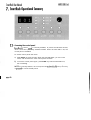
1
SER MANUAL
Thank you for choosing ARRl SmartRack digital dimmers. We are
sure that you will be pleased with SmartRack, and wish you a
long and happy association with our company and its products.
We at ARRl have done everything we can to ensure that your
new dimming system will function perfectly, will be easy to
install, and will give you many years of reliable service.
This manual contains detailed instructions for installing, using
and maintaining ARRl SmartRack dimmers. Please follow them
carefully, to guarantee best results. Neither ARRl (GB) Ltd nor its
distributors can accept any liability whatsoever arising from the
guidelines in this manual not being followed.
ARRI (GB) Ltd
1-3 Airlinks, Spitfire Way, Heston TW5 9NR, England
Tel: 081 848 8881 Fax: 081 561 1312
page i
.................................................................
2.1
2.2
2.3.
2.3.1
2.3.2
2.3.3
2.4.
2.4.1
2.4.2
2.4.3
2.4.4
2.5.
.
Mechanical ............................................................................ 2
Electrical................................................................................ 4
Filtering ................................................................................. 4
Standard risetime choke .......................................................... 4
High risetime choke ................................................................ 5
Extra high risetime choke (5kW and 1OkW only) ........................5
Rack control ...........................................................................5
Dimmer profile ....................................................................... 5
Response speed ......................................................................5
Dimmer test ............................................................................ 6
Reference voltage ................................................................... 6
Thermal management .............................................................. 6
......................................
3 Getting Started -. What's in the Box
8
3.1 .
SmartRack .............................................................................8
3.1.1 Rack ..................................................................................... 8
3.1 .2 Power assemblies ...................................................................9
. Installation .........................................................................1
4.1 .
4.2.
4.2.1
4.2.2
4.3.
4.4.
4.5.
4.5.1
4.5.2
Environmental considerations ................................................ 1 0
Planning and marking out ...................................................... 10
Marking out a wall ............................................................... 1 1
Planning an island installation ................................................ 12
..
Wall f~x~ngs
......................................................................... 12
Assembly and mounting ......................................................... 12
Power wiring........................................................................ 14
Standard SmartRack.............................................................. 16
Connecting to integral MCCBs ............................................... 16
rsi
4.5.3 Connecting single and bi-phase systems .................................. 18
4.5.4 Connecting Delta systems ...................................................... 18
4.5.5 Cascading a stack of SmartRacks .......................................... 18
4.6.
Load wiring.......................................................................... 20
4.6.1 Installing load wires .............................................................. 20
4.7.
Identifying and testing power and load wiring.......................... 20
4.8.
Signal wiring ....................................................................... 21
4.9.
Powerassemblies ................................................................. 22
4.9.1 Installation ........................................................................... 22
4.9.2 Connecting load wiring ......................................................... 22
4.9.3 Connecting power wiring - RCD option fitted ........................... 24
4.9.4 Connecting power wiring - without RCD option ....................... 26
4.9.5 The power assembly signal looms ........................................... 26
4.10
SmartRack door .................................................................... 28
4.10.1 Mounting the door ................................................................ 28
4.10.2 Connecting earth and power wiring ........................................28
4.10.3 SmartRack CPU jumper settings .............................................. 28
4.10.4 Connecting power assembly signal looms ................................ 29
4.10.5 Connecting DMX input/output wiring ...................................... 30
4.10.6 Fitting blanking plates ........................................................... 30
4.10.7 Closing the door ................................................................... 30
4.10.8 Fitting dimmer number strips .................................................. 31
. SmartRack in a Flightcase...................................................32
5
5.1 .
5.2.
5.2.1
5.2.2
5.2.3
5.2.4
5.3.
Ordering a flightcase ............................................................ 32
Designing a rear panel.......................................................... 33
Power connectors ................................................................. 33
Load connectors ...................................................................33
Patching .............................................................................. 33
Signal connectors ................................................................. 34
Wiring ................................................................................ 34
page iii
!
I
I
n
6.1.
6.2.
6.3.
6.4.
6.5.
6.5.1.
6.5.2.
6.6.
6.7.
6.7.1.
6.7.2.
6.7.3.
6.7.4.
6.7.5
6.8.
6.8.1 .
6.8.2.
6.8.3.
6.8.4.
6.9.
6.9.1
6.10
.
......................................
Switching on ........................................................................ 3 5
Power and signal indicators ................................................... 3 5
Modular SmartRack dimmer level indicators ............................. 3 6
Battery supported memory ..................................................... 3 7
Using offline mode ................................................................ 3 7
Verifying rms line voltage in offline mode .................... .
.
.......3 8
Setting the output voltage range in offline mode ....................... 3 8
Testing dimmer circuits with the rotary potentiometer ................. 3 9
DMX control ......................................................................... 3 9
Terminating the DMX line ....................................................... 40
Good/bad data ................................................................... 40
Setting the rack address ........................................................ 40
Large installations ................................................................. 4 1
Testing dimmers with DMX ..................................................... 4 1
Dimmer profiles .................................................................... 4 1
What is a profile? .................................................................4 1
SmartRack standard profiles ................................................... 4 2
Dimmer and console set profiles ............................................. 4 3
Setting profiles .....................................................................4 3
Response speed .................................................................... 4 4
Setting response speed .......................................................... 4 5
Important note - Exiting from user interface mode ..................... 45
.....................................
7 SmartRack Operational Summary
,
46
7.1.
Accessing the control panel .................................................... 4 6
7.2.
Address setting ..................................................................... 47
7.3.
Dimmer mode ...................................................................... 4 7
7.3.1 Testing dimmers at levels ....................................................... 47
7.3.2 Profile mode ......................................................................... 4 8
7.3.3 Speed mode ........................................................................ 4 8
7.4.
Offline mode ........................................................................ 49
page iv
7.4.1 Checking line voltage ............................................................ 5 0
7.4.2 Setting the output voltage scale .............................................. 5 0
7.4.3 Clearing configuration settings ............................................... 5 0
........................................................
e.*
8.1 .
8.2.
8.3.
8.4.
8.5.
Torque settings ..................................................................... 5 1
Cleaning ............................................................................. 5 1
Inspecting dimmer module connectors ..................................... 5 2
Control fuse ratings ............................................................... 5 2
Battery replacement .............................................................. 5 2
9 1.
9.2.
Who to call .......................................................................... 5 3
What to tell them .................................................................. 5 3
. Technical Support .........................................................*.....
53
.
........................................................
54
10 Accessories & Options
10.1
Inlet filters ............................................................................ 5 4
10.2
RCD protection .....................................................................5 4
10.3
Power circuit breaker ............................................................ 5 4
10.4
Single phase adapter kit ........................................................ 5 4
10.5
Ripple rejection card ............................................................. 5 5
10.6
Spare numbering sheets ........................................................ 5 5
10.7
Output phase terminal extender kits ........................................ 5 5
arts
........................................................................56
I
page vi
There are good reasons why users of professional dimming equipment are now only
willing to accept true digital dimmin g equipment, such as ARRl SmartRack and
SmartPack. They are:
Accuracy - digital dimmers are able to regulate output levels to reproduce precisely
recorded intensities, even when mains power is fluctuating.
Reliability - with fewer electronic components, digital dimmers literally have less
things to g o wrong.
Smarts - with processing power on board, digital dimmers can perform tasks previously impossible with analogue techniques. These include diagnostic functions, individual dimmer profile and response speed settings, and more.
Cost - a well designed digital dimmer typically uses fewer electronic components
and is therefore cheaper to manufacture.
The key to the accuracy of digital dimmers i s regulation. This means that the dimmer is
constantly measuring the rms voltage of each supply phase (a total of 12,800 times per
second in the case of ARRl SmartRack) to build up an accurate picture of the condition
of the mains supply to each dimmer. Using this information, the power devices are precisely controlled, to compensate for any mains voltage fluctuations and produce a constant voltage output for any given control level.
Of course, in an age where virtually all lighting control consoles output the same internationally accepted digital control signal (USITT DMX512), another plus with digital
dimmers i s that no expensive demultiplexer stage is required. The digital signals from
the lightboard are simply connected directly to the dimmers.
SmartRack i s a revolutionary concept in professional digital dimming equipment, offering a very wide range of system options in an extremely compact packoge, with many
significant advantages over its competitors:
Compact size
Competitive price
Easy and economical installation
Highly flexible configuration options
Easy to flightcase
Basic or modular variants
All-digital -
high reliability,
high accuracy
SmartRack i s unique in that it offers competitive system solutions at all levels of the market, and versions exist to cover all requirements, right up to top level broadcast applications.
Each SmartRack i s a proprietary wall mounting steel cabinet, measuring 85cm
wide, 65cm high and 30cm deep, designed to house up to three power assemblies (supplied separately), each of which comprises 3 0 k W of dimming, as either
12 x 2.5kW, 6 x 5kW or 3 x 10kW. A hinged steel front door supports all the
system electronics, and the rack is available in two versions, to accept either
basic (hard-wired) or plug-in modular power assemblies.
SmartRack is primarily intended for wall-mounting, and may be installed up to
three high, side by side, or back to back. SmartRack may also be fitted into
flightcases with custom rear connector panels, for highly cost-effective mobile
dimming systems.
All
power, load and signal cables may enter from top, bottom, or through rear
panels and sufficient space is provided for through wiring in a stack of three
SmartRacks. Front access only is required for installation and maintenance, and
all terminal screwheads face forward, for easy re-tensioning in service.
ower Assemblies are available either with plug-in modules containing power
devices and LED level indicators, or with power devices mounted on a permanent heatsink. Power assemblies of different ratings may be mixed in a rack, but
basic and modular power assemblies may not be mounted in the same rack.
All
controls for rack configuration are mounted on the front panel, and the start
address of the rack is normally displayed, along with power, DMX and thermal
status indicators.
Front view of a modular
SmortRock, showing key
dimensions.
Note that SmartRock is
300mm deep, plus 30mm
for dimmer module hondles
on the modular version only.
650
rncb centre
496
rncb centre
290
rncb centre
SmartRack i s designed for operation on single or three phase supplies at
230Vac 12.5%. Delta versions are also available to special order.
Each SmartRack may optionally be supplied with a 4-pole 125A or 160A circuit
breaker fitted, and earth leakage (RCD) protection may be fitted at power assembly level (three phase systems only).
Power devices are generously overrated solid state switching devices, encapsulated into quad 2.5kW, dual 5kW and single 1OkW modules.
Individual dimmer circuits are normally protected by single pole miniature circuit
breakers, rated at 13A (2.5kW), 25A (5kW)and 50 A (10kW). Single pole with
neutral disconnect mcbs and double pole mcbs are also available to special
order. See the SmartRack specification for more detailed electrical information.
SmartRack dimmers are designed to conform to the EMC requirements of
EN55014 and EN55022, the usually accepted European norms specifying RFI
interference suppression requirements. In addition, low frequency filtering is
achieved to different levels, depending on the choke specified. Three different
choke styles are available, offering different current risetimes, as required for different types of work. Generally speaking, the higher the risetime the more the
interference generated by the dimmer i s suppressed, but it is unwise to specify a
higher risetime than that actually required, since there are weight, thermal and
cost penalties as you go up the scale.
Standard risetime choke
The standard choke is wound on a 2.5" toroidal iron powder core, and
produces a risetime in excess of 200uS. This should be adequate for theatre a n d most video production work, and complies with the BBC's
P I D l 7 l standard for 2 . 5 k W dimmers.
The High Risetime choke is wound on a 4" toroidal iron powder core, and
produces a risetime in excess of 400uS. This i s a requirement of the
Nordic Television Authorities for 2.5kW dimmers, and complies with the
BBC PID171 standard for 5kW and 1 OkW dimmers. It is recommended
for front of house lighting circuits in theatres and in concert halls, where
acoustic requirements may be critical.
xtra high risetime choke (
This choke is wound on a special 4" hybrid core, and produces risetimes
in excess of 700uS, required by the Nordic TV authorities for 5kW dimmers. It may also be appropriate in situations where absolute levels of
acoustic silence are required, such as symphony halls. The EHR choke is
limited to 5kW and 10kW dimmers only.
. Rack control
SmartRacks receive USlTT DMX512 (1990) dimmer drive signals from a very
wide range of lighting controllers, including all ARRl Mirage, Impuls, Imagine,
Connexion and Reflexion systems.
The control panel on each SmartRack enables the user to set and display a start
address for the rack, as well as to select, for each or all dimmers:
2.4.1 Dimmer profile
Any dimmer may be set to any one of 12 preprogrammed curves, including three non-dims and a 'hot' setting (permanently on). This should take
care of the requirements of the vast maiority of entertainment and architectural applications, and custom profiles may be generated if required.
2.4.2 Response speed
A dimmer's response speed is the time it takes for the dimmer's output to
arrive at a new level, following the reception of a new level instruction by
the dimmer's control electronics, and is measured in milliseconds. Don't
confuse response speed (in milliseconds) with risetime (in microseconds).
SmartRack ships with a default 100mS response speed set for all dimmers,
but allows the user the choice, for any or all dimmers in o rack, of 30,
100, 3 0 0 or 500mS.
Thus, a studio with RCDs and a lot of 5kW loads might function happily
with all dimmers set to 300mS response time, while individual circuits for
chasers or practicals might be set to 30mS for special effects work. A touring rack used for concert lighting, on the other hand, might be set globally
to 30mS, but with the odd 10kW dimmer at 500mS.
IMPORTANT: A slower response speed will also have beneficial effects on
lamp life, since the shock to cold filaments will be reduced, as the time
period required to ramp them to full brightness is increased.
Any or all dimmers may be selected and set to a level, using the rotary
potentiometer on the front panel. The dimmers in a rack may be 'flashed
through1 to a level, by setting the pot to the desired intensity, and stepping
through the dimmers using the A or
.4 Reference Voltage
SmartRack needs to know the volta g e expected b y the user for full on
( l o o % ) , to which all other levels are scaled. This reference voltage is set
by the user or installer, using the rack controls.
hermal Management
SmartRack runs remarkably cool, and uses computer controlled brushless dc fans
to d o so with minimum noise and maximum fan life. One fan is incor p orated into
the end of each power assembly, and air is drawn very efficiently over the
chokes and power device heatsinks before being exhausted through the front
panel.
Since SmartRack's air inlet and exhaust vents are all on the front panel, there i s
no problem stacking SmartRacks vertically and horizontally, or mounting in simflightcases.
One thermal sensor is provided for each power device, and constantly feeds
back temperature status information to the central processor (CPU). The CPU uses
this information to decide when it is necessary to switch on the fan for any given
power assembly. In the event that a power device should run hot, an amber
warning signal is lit on the front panel. If the device overheats, it will be shut
down, and the warning LED will flash red.
The thermal indicator LED may be wired to a remote panel, or incorporated in
control room furniture, to provide a simple (geographic) dimmer room mimic
panel, showing rack power and temperature status.
SmartRack systems are shipped broken down into racks and power assemblies
(up to three per rack). Please check carefully to verify that you have everything
you need before starting the installation.
Each rack is shipped separately as an empty enclosure, with separately
wrapped door assembly and a number of internal fittings kits, namely:
etalwork Kit
2 x power cable entry cover
2 x load cable entry cover
Hardware Kit
Door Kit
2 x M4 black washer
1 x M4 shakeproof washer
1 x M4/10 Pan Posi Screw
1 x graphics layer number sheet
Entry Cover Kit
32 x M4/6 taptite screw
32 x M4 spring washer
Fan Kit
3 x M5/10 Pan Posi screw
3 x M5 nylon washer
Foot Kit
4 x plastic feet
4 x M5/16 csk screws
4 x plastic plugs
Power Terminal Safety Cover Kit
1 x Plastic Safety Cover
3 x M5/12 taptite screw
Remove the door assembly from the carton and store it separately while
the racks are installed and wired. It's not needed until the installation of
the wiring and power assemblies is complete.
Power assemblies are packed individually, and are of two main types basic or modular. Basic power assemblies come with the power devices
permanently mounted on a single heatsink on the front of the assembly.
Modular power assemblies are each provided with three plug-in dimmer
modules containing the power devices and level indicators.
When installing modular power assemblies, first remove the plug-in modules and store separately in a safe place until ready.
Each power assembly is also shipped with
Power Loom Kit
1
1
1
1
1
L1
x 2.5mm2 cable. Brown ident L2
x 2.5mm2 cable. Brown ident 13
x 2.5mm2 cable. Blue ident N
x 2.5mm2 cable. Brown ident
x 2.5mm2 cable. Yellow/green ident
Hardware Kit
5 x M5/10 Hex head screw
6 x M5 shakeproof washer
1 x M5/ 10 Pan Posi screw
2 x IOmm2 uninsulated bootlace ferrules
Note that the power assemblies are not required for the first stages of
installation, and should be left in their packing, esp ecially if there is a risk
of builders' dust on site.
SmartRacks are intended for mounting either against a wall, bock to back in an island
formation or in a flightcase. This section deals with wallmount or island installation see the next section for information on flightcasing.
Care must be taken to ensure that the ambient temperature in the dimmer room
stays within the range 0 - 35" Celsius. In some cases, this will require air extraction or air conditioning.
In order to calculate worst case air handling requirements, you need to know the
thermal losses in the dimmer, as well as estimating the actual maximum continuous load. Since lighting loads vary enormously, it may be reasonable to apply a
diversity factor of between 0.5 - 0.8 to the actual connected load, to represent
worst case.
The formula for calculating the heat generated by the dimmers (in watts) i s therefore:
Total connected load x diversity factor x (100 - efficiency %)
Or, for example:
250,000 x 0 . 6 x (100 - 98%)
= 3,750 watts
Here, a diversity factor of 0 . 6 is applied to a 250kW load, assuming 98% efficiency at the dimmers (which is reasonable). The result is that up to 3.75kW of
heat may be anticipated in the dimmer room, which may then need additional
extraction or cooling.
Relative humidity should be kept below 80%, noncondensing
4.2 Planning and marking out
SmartRacks are intended to be mounted up to three racks high, and as wide as
may be required, with no air gap between racks.
Wiring access may be from above, from below or through the rear, and only
front access is required for installation and service.
W e recommend using a large cable duct running across the top of a bank of
SmartRacks, carrying power and load wiring. Alternatively, power wires may be
run in From below, and load wires from above, or vice versa.
Note thai DMX signal wires should be run in separate cableways from the power
and load cables, outside the racks, though it is permissible to mix them in the
immediate vicinity and inside the racks themselves.
Use the dimensions below to mark out a grid o n the wall where the
SmartRacks are to be installed. Note the height and width of the racks and
the mounting centres:
Two stacks of three
SmartRocks, showing posi
lions of fixing holes. 13mm
has been allowed for the
feet at the bottom of each
stock, which are optional.
I
j
Stack 2
I
i
I
I
I
I
Rack:
h 650mm,
w 850mm
ounting centres:
h 560mm,
w 760mm
....
J..
....
....
....
....
....
....
....
page 11
SmartRacks may be mounted back to back, either in an island, or, with
configuration.
one end of each bay against a wall, in a
On a solid floor, all wiring will normally be taken out through the top
wiring access ports. Where raised computer type flooring i s used, some or
all of the wiring may enter through the base of the rocks.
Note that the 'keyhole' fixing positions in the back of each rack must be
used in back-to-back installations, to provide stability. Use M 6 nuts and
bolts to fix back-to-back racks together.
A knockout panel is provided in the centre of SmartRack's rear panel,
which may b e removed i f interwiring between back-to-back racks i s
required. If using the knockout panels, use a grommet strip around the
inside edges to prevent chafing.
. Wall fixings
Each SmartRack weighs between 75-85kg, depending on version used, and is
fixed to the wall at four points. Making an allowance for cable of 20-25kg per
rack, this means that each fixing has to support no more than 30kg. The actual
fixing used will depend very much on the wall material and condition, but on a
brick or concrete wall, 50 x 5mm woodscrews, used in conjunction with correctly
installed plastic wall plugs, should be more than sufficient.
uneven surfaces, it may be necessary to mount 50 x 50mm wooden battens
to the wall, and fix the SmartRacks to the battens. In this case, ensure that the
batten fixings are sufficient to take the total weight of all the SmartRacks to be so
mounted.
On
Having marked out the wall, drill, plug and fit mounting screws, protruding about
20mm from the wall.
. Assembly and mounting
a) If the bottom SmartRack in a stack will stand on the floor, fit the four plastic
feet provided, by screwing them up into the threaded inserts on the base of
the rack.
Plastic plugs
(f)
How to fix two SmomPock
enclosures together. Mounting 'keyholes' (c)
Fit power and lood coble
entry cover plotes fo top and
bottom of f i e stack os
required, but not in between
SmortRocks in 0 stock.
M5 Fixing screws (d)
Plastic feet (a)
and M5 fixing
I
7
7
I
t
screws
page 13
If required, fit the bottom cable entry cover plates provided to the base of the
bottom SmartRack, using the taptite screws provided. These plates should be
used if forming or glanding is required, or, unworked, to blank unused cable
entry ports.
Hook the bottom SmartRack in each stack onto the four fixing screw heads
alread y in the wall, locating the four 'keyholes' in the rear panel to the
screws in the wall. Partially tighten screws.
Fit the upper SmartRack(s) in the stack to the wall fixing screws in the same
way, then, using the M5 screws provided, fix the racks in the stack together
by screwing into the threaded holes in the upper rack(s), through the matching clearance holes in the rack(s) below.
Tighten all wall fixing screws.
Fit the four plastic plugs provided into the four holes in the top surface of the
top SmartRack in each stack.
If required, fit the top cable entry cover plates to the top surface of the top
SmartRack, using the taptite screws provided. These plates should be used if
forming or glanding is required, or, unworked, to blank unused cable entry
ports.
. Power Wiring
SmartRack i s primarily intended for use on five wire services, where the phase to
neutral voltage i s 230Vac
12.5%. However, single, bi-phase and delta wiring
is also possible, and the various alternatives are dealt with below.
The current draw of any dimmer rack i s hard to predict, and i s always subject to
major variances. A reasonable way of assessing the current requirement per
phase is:
Total connected load (watts) x Diversity factor
(voltage x 3)
(0.5 - 0.81
Estimating the diversity factor i s a matter of judgement, and depends very much
on the type of installation and its working practices. It may also be that the installation as a whole may have a diversity of 0.5, while individual racks may expect
0 . 8 or even higher.
Wiring in power feeder
cables fo 5 standeid
SmartRock.
Note iJ2ot power wiring to
other SmartRocks in o stack
should be tied back to the
cable way provided down
the inner left wall of the
enclosure.
page 15
NOTE: If the mains circuit breaker option (MCCB) is not fitted, adequate protection must be installed upstream of the SmartRack(s).
Standard racks require a five wire supply, terminated in eyelet (ring) lugs,
to fit the MI2 terminal screws provided.
Run the power wires into the power terminal block, via the top or bottom cable entry on the left side of the rack. Cable tie anchors are provided iust inside the cable entry ports.
Note that a cable way, with slots for cable ties, is provided to lead
power wires up and down the left side of the enclosure to feed other
SmartRacks above or below.
Trim to length and terminate with MI 2 clearance lugs. Do not fit the
plastic terminal block cover at this stage.
Connecting to integral MCCBs
Where the MCCB option i s fitted, a 4-pole moulded case circuit breaker
has been factory installed in the SmartRack, and wired to the power terminal block. Input phase and neutral wiring is therefore terminated to the
cage terminals in the MCCBs, and the earth only is terminated to the
power terminal block.
Run the power wires into the bottom of the MCCB, via the top or bottom cable entry on the left side of the rack. Cable tie anchors are provided lust inside the cable entry ports.
Note that a cable way, with slots for cable ties, is provided to lead
power wires up and down the left side of the enclosure to feed other
SmartRacks above or below.
Trim to length and terminate in the caged terminals provided.
Run the earth wire to the earth terminal on the power terminal block,
and terminate with an MI2 clearance lug.
Do not fit the plastic terminal block cover at this stage.
Wing 0 SmortRock with
integral moins circuit breoker
(MCCB) fitted.
Conned incoming phose ond
neutral feeds to bottom of
MCCB - wiring fmm MCCB
to power terminals is fortory
fined.
Conned eorfh wire direct to
power terminal.
page 17
SmartRacks (without MCCBs) may be connected to single or bi-phase supplies, if a single phase adapter kit (part number Y2.SR002.0) is used.
The kit comprises two nickel plated copper plates, which replace the existing L1, L2, L3 & N terminals (single phase use only). See diagram.
One plate i s fixed across the LI & L2 studs with the nine equi-spaced holes
to the right; these are connected to the bottoms of the channel circuit
breakers with the standard set of live cables.
The other plate is fixed across studs L3 & N with the three large holes to
the right. These connect to the neutral terminal block (located to the right
of the channel circuit breakers) with the three heavy cables provided in the
adaptor kit.
Having fitted the plates, installation is as for standard SmartRacks (see
above).
arning: RCDs cannot be fitted to single phase SmartRacks.
Y2.SR002.0 contents:
2 x plates
3 x neutral cables (35mm2)
3 x earth cables (1 6mm2)
.4 Connecting Delta systems
Power wiring is as for standard SmartRacks, except that the neutral terminal is unused.
Warning: only SmartRacks supplied to operate on delta
power can be connected to delta power supplies.
4.5.5 Cascading a stack of SmartRacks
In a stack of two or three SmartRacks, it may be preferred to protect the
whole stack from one offboard circuit breaker or switchfuse. In this case,
wire from the switch to the first rack (top or bottom, as convenient), then
make up short power cables to link from the power terminal block in the
first rack to the second, and so on.
Wring a standard
SmartRock for single phase
operation, using ffie
SmarlRock single phase
adaptor kit.
page 19
All load wiring enters the SmartRack(s) by either the top or bottom load entry
port in the large centre section of the rack. SmartRack is primarily designed for
load wiring with single core cables in cableways, but may also be wired with
three core or multicore cables.
ire
Run in all load wires for each SmartRack or stack of SmartRacks through
the top or bottom load cable entry port. Columns of cable tie anchors are
provided, for earth, neutral and phase wires respectively (see diagram).
Bunch wires together and tie bunches to cable tie anchors, peeling off the
wires for each power assembly at the appropriate row of cable tie
anchors. Trim to 33cm from the cable tie anchor to the cable end.
If multicore cables are used, distribute them evenly across the cable tie
anchors provided, and allow enough length at each power assembly level
to strip back the outer sheath sufficient to reach all terminals (allow 80cm).
Ensure that all wires are correctly labelled with circuit number and function
(phase, neutral or earth).
entifying and Testing power and load wiring
It i s essential that all power and load wiring be correctly identified
and tested using a high voltage insulation tester, before installing
power assemblies or SmartRack electronics.
Use a low voltage tester to identify load pairs, and label accordingly, prior to
carrying out a high voltage insulation test.
Inspect for polarity and carry out a high voltage insulation test on all power feed
wiring.
Do not attempt a high voltage insulation test with any SmartRack
assemblies connected as this will destroy electronic components in
either the power assemblies or the control electronics.
Earth
1 P2
laying in the lood wires.
Note the arrangement of
wires into Earih, Neutrol and
phase wires, according to
the phase of the load circuit
(PI, PZ or P3). laying the
wires in this way makes
connection to the Iwd
terminals an the power
assembly easy and quick.
If using three core or
multicore cables, spread
them evenly across the nine
cable bunches, and ship
back the outer insulation to
the cable tie.
lood wiring for other racks
in the stack should be
bundled with the wires
shown, and passed through
the cable port to the rack
above or below, then laid in
as shown.
Neutral
1 P2 P3
Phase
1
2
3
. Signal wiring
SmartRack uses the international digital dimmer standard USITT DMX512 ( 1 990)
to receive dimmer drive signals from a controller. DMX wiring requires twisted
pair and overall screen cable (Belden 9841or equivalent), rated for RS485.
The signal cable loops from rack to rack, and will be terminated to the electronics on the front door. For the time being, run the cable continuously through the
racks, using the power wiring chamber, allowing about 1 m of slack for termination in each rack.
page 21
Note that, while signal cables should be kept away from power and load cables
in cable runs outside the rack(s), no harm will be done by their close proximity
inside the SmartRack enclosure.
Unpack the power assemblies. If installing modular power assemblies,
set the plug-in modules aside in a safe place.
Remove the fan plate from the SmartRack, by releasing the three fixing screws and pulling the fan plate towards you.
Starting with the bottom position in the SmartRack, slide in the power
assembly, with the circuit breakers to the left. Ensure that all the load
wires to be connected to the power assembly are laid over the top of
the power assembly, and do not fall behind it.
Fix the power assembly in place by screwing the left side into the
threaded hole in the back of the rack's power assembly slot, using the
M5 screw provided. Do not fix the right side for the time being.
Repeat steps
(b) to (d) for
the middle and top power assemblies.
Slide the fan plate back into position, ensuring that the tabs on the
three blades of the fan plate locate in the bases of the three power
assemblies. Fix the fan plate back in position with the three fan plate
fixing screws, and plug the fan cable plugs into the receptacles on the
face of each power assembly (in part-populated racks, there is no
need to plug in the fan connector where no power assembly is present).
4.9.2 Connecting load wiring
Carry out the following steps for each power assembly. If the wires are
correctly laid in the back of the SmartRack, they should line up well with
the load terminals on the face of the power assembly.
Please note the following maximum cable sizes:
Earth and Neutral bars:
2 . 5 k W Phase terminals:
5kW Phase terminals:
10kW Phase terminals:
10 x 10mm2, 3 x 16mm2
4mm2
6mm2
3 5m m2
It is occasionally necessary to use larger cable sizes on the 2.5kW and
5kW dimmers, and an adapter kit is available, with 10mm2 and 16mm2
DIN terminals for oversized cables. See section 10.7 for part numbers.
Note that bootlace ferrules are required to be fitted to the earth and neutral wires if stranded cable is used.
a)
Terminate load earth wires into the earth busbar on the left side of the
power assembly. Recommended tightening torque 1.5Nm (2.5mm2
cable) to 2 N m (10mm2 cable).
Terminating load wiring.
Note hat numbering is
always from left to right, ie:
E a h 1-12, Neutml I-12,
Phase 1- 12. f i e same rule
applies to 3x 1Ok W and
6xSkW Power Assemblies.
Tip:
It's easier to fit the
bottom Power
Assembly first,
terminate the load
wirin5 then fit the
middle Power
sembly, and so on.
page 23
nual
b)
Terminate load neutral wires into the neutral busbar in the middle of
the power assembly. Recommended tightening torque 1.5Nm
(2.5mm2 cable) to 2 N m (10mm2 cable).
Note that bootlace ferrules are recommended if stranded cable i s
used.
c)
Terminate the load phase wires into the three groups of output terminals. Recommended tightening torque 1 N m (2.5kW dimmers), 2 N m
(5kW dimmers), 1.2Nm (10kW dimmers).
Connecting power wiring
-
Each power assembly has to be connected to the power terminal block,
using the part-assembled power loom provided. There are slight differences, depending on whether the power assembly is fitted with RCD protection or not. If not, skip to the next section.
a) Terminate the five wires to the appropriate terminals on the power terminal block, using the M5 hex-head screws provided. Recommended
tightening torque 2Nm. The colour code is 11 - L3 brown, Neutral
light blue, Earth green/yellow. Form the five wires into a loom, and
run to the top of the power assembly's RCD.
b) Trim to length and terminate the three phase and one neutral wire into
the RCD's caged terminals, in sequence (from the left):
13- 12- 11 - N
Recommended tightening torque 2Nm.
c)
Trim to length and terminate the earth wire into the left position of the
earth bar, entering from below. Use the bootlace ferrule provided to
protect the stranded cable and ensure good earth contact.
Recommended tightening torque 2Nm.
Wiring the power feeds from
the power terminals to fhe
P~werAssembly RCD. Note
the omkr of connection to
fhe RCD.
For the sake of clorily, only
one Power Assembly
connection is shown.
page 25
ectin
Terminate the five wires to the appropriate terminals on the power terminal block, using the M5 hex-head screws provided. Recommended
tightening torque 2Nm. The colour code i s L f - 13 brown, Neutral
light blue, Earth green/yellow. Form the five wires into a loom.
Route the three phase wires around the top of the power assembly
(see diagram) to the bottom of the circuit breakers. Trim to length and
terminate to the inlet terminals of each group of circuit breakers, in
sequence (from the left):
-
Recommended tightening torque 2Nm.
Trim to length and terminate the earth wire into the left position of the
earth bar, entering from below. Use the bootlace ferrule provided to
protect the stranded cable and ensure good earth contact.
Recommended tightening torque 2Nm.
Trim to length and terminate the neutral wire into the DIN terminal to
the left of the circuit breakers. Recommended tightening torque
1.2Nm.
Note: routing the phase wires past the neutral terminal ensures that,
should it be necessary to retrofit an RCD to the power assembly later
on, this may be easily done.
.9.5. The power assembly signal looms
Until the front door is fitted, there is no point in running in the power
assembly signal looms. See 4.10.2 below.
Wiring the power feeds from
the power terminols to the
Power Assembly. The three
phase wires ore terminated
into the caged teminols on
the three blocks of dimmer
circuit breakers.
For the sake of clarify, only
one Power Assembly
connection is shown.
Tip:
un the three phase
wires past the neutral
terminal as shown;
this makes it easy to
retrofit RCDs later, if
required.
page 27
The door mounts on the left side of the rack, and supports all the rack electronics.
ounting the Smart ack door i s the last part of the installation procedure.
a)
remove the door from its packaging.
b)
Using the two hinge screws and 3.5mm
spacers provided, mount the door in the
SmartRack chassis.
Fining the hinae screws
Tip: Extend the bottom screw fully, slide
on a spacer, a n d fit into
first. Then,
with the top screw protruding 3-4mm, fit
top spacer, locate top mounting and
screw top screw home.
Note that the fit of the bottom mounting is
deliberately loose. This tightens automatically when the door i s closed and
screwed shut.
'yg
lnge screw -""-
onnecting earth and power wiring
a)
Connect front door earthing wire to the adiacent stud in the chassis,
using an M4 nut runner.
b)
Route the CPU power loom and terminate to the power terminal block,
following the coding labels on the loom wires.
c)
Fix the clear plastic cover of the power terminal block in position,
using the M5 taptite screws provided.
martRack CPU jumper settings
Set the three iumpers J1, J2 and 53, according to the power rating of the
power assemblies in the top, middle and bottom positions in the rack:
3
2x2.5kW
6x5 kW
3x1 OkW
3
3x1 OkW
6
53
ottom Power Assembly
12
12x2.5kW
6
6x5 kW
3
3x1 OkW
54
R
P
0
56
SmartRack
SmartPack
Spare
DMX Terminafion
U
Unterminated
T
Terminated
DMX Input/Output Terminal
D+
Data +
DData SCR
Screen (ground)
4.10.4 Connecting power assembly signal looms
Using the flat ribbon cable clips mounted inside the SmartRack, run the ribbon cable from the top power assembly around the top of the rack, and
terminate to the top position on the SmartRack CPU. Fold any excess cable
flat inside one of the cable clips.
In the same way, run the ribbon cables from the middle and lower power
assemblies around the bottom of the rack, and terminate to the middle and
lower positions on the SmartRack CPU. Fold any excess cable flat inside
one of the cable clips.
~
nnecti
in
Route the DMX in and out wires to the bottom of the CPU and trim to
length. Terminate both the DMX in and out wires into the same terminals
(CON8), as indicated on the previous page.
Depending on the type of power assembly fitted in each position, one or
more blanking plates may need to be fitted to the inside of the front door.
All power assemblies without RCD protection are supplied with a blanking
plate. 5kW and lOkW power assemblies are also supplied with blanks,
to compensate for the smaller width required for their circuit breakers.
Where a power assembly position remains unused, you must fit a power
assembly blanking plate (part no Y2.SR001.0).
To fit blanking plates:
a)
Offer blanking plate into position inside door. Note that mcb and
RCD blanking plates have a double thickness of material which
extends into the door's mcb slot.
b) Using an M3 nut runner, remove the M3 nuts and washers from the
studs required to fit the blanking plates.
c)
Fit the blanking plate(s)in position, then replace and tighten the M3
washers and nuts.
Note: if SmartRack i s only partially populated with power assemblies, then
blanking plugs must be fitted to unused outputs of the CPU board. Please
contact ARRl engineering.
4.1 0.7 Closing the door
Check that all wiring i s properly terminated and that no tools or other
items are left in the rack.
Swing door shut, and adiust line-up. Tighten three fixing screws.
page 30
Self adhesive numbering strips are provided to give smart and permanent
identification of dimmer numbers on the front of the rack. Each SmartRack
is provided with one sheet containing the numbers 1-240. Spare sheets
and higher numbers are available from ARRI, under the followin g port
numbers:
a)
Y2.SR003.1
1-240
Y2.SR003.2
2 4 1-480
Y2.SR003.3
4 8 1-720
Y2.SR003.4
7 2 1 -960
Simply peel off the numbers required and cut strips to length with a
pair of scissors as necessary.
b) Press into place above the appropriate circuit breakers, in the detent
left by the cutout in the door's graphic layer.
c)
Fill any gaps
(to the right of the circuit breakers on 5kW and lOkW
dimmers) with the blank strips provided.
Peel off numbering strips
ond press into ploce on the
fmt ponel.
Spore sheeb of numbers
may be obtoined fiom ARRI
lighting Control distributors.
page 31
SmartRack i s ideally suited to flightcasing b y rental and touring companies, offering o
superbly specified dimmer, and a wide range of configuration options. Provided some
basic guidelines are followed, this can be a painless and very cost-effective way of presenting dimmers for the road.
eri
Using the dimension guide below, any flightcase company will have no difficulty
in producing a case, ready to accept one standard SmartRack and a custom rear
panel.
The SmartRack will fix into the blocks shown, which have to be strongly fixed in
place. Allow 25mm foam around the top and sides of the SmartRack to provide
some cushioning in transit.
!
!
!
lnternal lid foam: Modular SmariRack 25mm dearance for
Internal wood
Internal wood
strips for rear blods for fixing ( e x ~ ~ ~ e r - module handles, Basic SmwtRad fill lid wih foam
panel mounting
to SmortRack
faam lining)
Hardwood skids interlock top and bottom for stacking
I
b
850mm inside foom
E
5:
a,
x
.-E
E
E
0
td3
rg
line front portion of
case with 25mm
plastic foam
Wooden fixing blocks
must be strongly
anchored to side walls
of case. Fix SmartRack
through four corner
'keyholes' into fixing
I
.
-
page 32
Fix a wooden strip 25x25mm around the inside of the back of the main body of
the case, so that the rear panel can be simply fixed using woodscrews.
Alternatively, fit 19" rack mounting beams, and fix using ca g ed nuts.
Provide stacking feet, so that racks may be stacked up to three high when in use.
Note that, since all ventilation is through the front panel, no provision for ventilation is needed in the flightcase itself.
Use the dimension guide above to make a rear panel to use with the flightcase
dimensioned above. The rear panel may be hinged, if preferred, for ease of
maintenance.
5.2.1 Power connectors
Any (legal) type of power connector may be used, depending on the
user's preferences and the style of operation. Bear in mind that the total
rating of a fully populated SmartRack is 90kW - 136 amps per phase at
220v. Allowing some diversity, this works very well on a single 125amp
three phase supply, or on a single phase 400amp supply.
Follow the power wiring instructions above to connect the power inlet connectors to SmartRack's power term inal block or MCCB.
.2.2 Load connectors
Any type of load connector may be used, either single or double outlets or
multipin sockets. Wiring back to the load terminals as described above for
permanent installation.
5.2.3 Patching
Many users now require either
or series patching at the dimmer
rack, and SmortRackls relatively large rear panel area makes it easy to
incorporate a custom patching system on the rear panel.
page 33
~
Allow for one male and one female XLR5 connector on the rear panel,
and wire to the SmartRack CPU as described for permanent installation
above. The pinout for the XLRs is:
Pin 1
Pin2
Pin 3
Pin 4
Pin 5
Ground
DataData +
spare
spare
W e recommend using single core tri-rated flexible cable to wire between the rear
and the SmartRack load and power terminals.
ane el
Note that the knockout panels in the power and load sections of the SmartRack
rear panel should be removed, and the apertures lined with grommet strip,
before wiring begins.
Route power and DMX cables through the smaller knockout in the back of the
power section of the rack, and load cables through the larger knockout in the
centre section.
page 34
a) For the first switch-on only, first set all MCBs and RCDs (if fitted) to the off
(down) position.
b)
Switch on power to the rack, and check that the three yellow power supply
LEDs 11, 12 and L3 are on, indicating that power from all three phases is
reaching the power supply section. If not, switch off, check wiring and
repeat.
c) If RCDs are fitted, switch them on. If any RCDs trip at this stage, there i s an
earth wiring fault in the dimmer rack.
d)
Switch on MCBs, one by one. If any RCDs trip at this stage, there is a powerfault in the power assembly.
SmurtRack Control Pone/,
showing default start
address (0011
ower and signal indicators
The following status indicators are provided on the control panel. Check that
their status i s correct before continuing:
page 35
a) Power LEDs L l , L2 and 13 (yellow). Should be on, indicating power from
three phase terminals reaching power supply section of CPU. Note that, in
single or bi-phase installations, all three LEDs should still light, though two or
more may be connected to the same supply phase.
b) DMX good data LED (green) - indicated with a
- on
if good DMX data
being received.
i s flashing, DMX data address has not been found.
It i s not necessary to receive DMX at this stage in the commissioning process.
c) DMX b a d data LED (red) - indicated with a - on if DMX data is missing or
corrupted, in which case it will be ignored by SmartRack.
If red LED flashing, DMX signal has been lost.
It i s not necessary to receive DMX at this stage in the commissioning process,
so, providing the system's DMX source is not on, a red DMX indicator is fine.
d)
Temperature status LED (tricolour). This LED should normally show green, indicating that all power devices are within a safe temperature range, and operation i s normal. The three states of this LED are:
Green
Normal operation.
Amber
One or more power devices are getting hot, but
operation is safe.
Flashing red
One or more power devices are over temperature and
have been closed down. They will resume normal
operation when a safe operating temperature has been
reached.
. Modular SmartRack dimmer level indicators
An advantage of modular SmartRacks i s that each dimmer i s equipped with a
level indicator LED, on the front panel of the dimmer module. This (green) LED
varies in intensity to approximate to the actual dimmer level. This i s most useful in
testing and commissioning, since it proves the entire electronics and control
chain, as far as (but not including) the power device itself.
SmortRack stores its confi g uration parameters in battery supported memory,
which will support settings for up to ten years. These batteries will have to be
replaced at approximately ten year intervals.
There are two levels of access to SmartRack1s control panel, which is normally
safeguarded from accidental operation. The first level is used for dimmer testing,
plus changes to dimmer addressing, profiles and response speed. The second
level - offline mode - is used for commissioning and service only, and requires a
special entry code, which may be withheld from operational staff if desired.
In offline mode, engineers can:
e
e
e
Check the rms line voltage
Set the output voltage scale
Clear configuration settings
To enter offline mode, it is first necessary to unlock the control panel:
a) Press enter for three seconds. The enter LED lights, indicating that the control panel i s unlocked. Note that the control panel has a three minute timeout. This means that the control panel will lock up if no buttons are pressed in
normal operating mode, after a period of three minutes. This time-out does
not apply in offline mode.
b) Press the A and
keys simultaneously for one second; three dashes appear
in the display window, indicating that SmartRack is in offline mode.
Note: in offline mode, the current DMX input is set to zero.
c) Use the A and
---
AC
CAI.
CLr
V
keys to move around the offline menu. The menu items ore:
Offline menu header
Check rms line voltage
Set output voltage scale
Clear stored values to factory defaults
d) To exit the offline menu, press A and V together from the offline menu
page 37
e) Then, to lock up the control panel, press
automatic time-out.
a)
en
, or wait three minutes for the
From the offline menu, Select AC, and press enter. The display shows
b) To exit, press enter. The display returns to the A
a)
From the offline menu, Select CALI and press enter.The display
shows the present rms voltage set for 100% dimmer output, eg 22
keys to change the rms voltage output scale, in
steps of one volt.
c)
Press enter to save the new value and exit to the offline menu.
This function has a very useful by-product: for example, in a TV studio
where the dimmers are being fed from their own transformer, it may make
sense to specify, say, a 240V supply, where 220V lamps are to be used
in the studio. Given that a loss in the region of 4V rms can be expected at
the dimmer (dependent on choke type), plus an average cable loss - say
3V rms (dependent on installation), the highest voltage that can be delivered to the lamp will be around 233V. But b y setting the SmartRack reference voltage to 227V, the dimmers will regulate to provide a constant
220V at the lamp, even though supply voltage may fluctuate at any level
above 227V.
This means that, unlike many digital dimmers, SmartRack is able in these
circumstances to regulate accurately over the full dimming range, not just
at levels below 100%.
Using the rotary pot on the control a an el, you can test any or all of the dimmers
in a SmartRack, without requiring external dimmer drive signals (DMX). This is
the next stage of commissioning:
ise (off position). If the control
or three seconds to gain access.
er, to enter dimmer mode.
keys to select the dimmer to test.
Turn the level pot clockwise to raise the level of the selected dimmer. In
modular SmartRacks, the green level LED on the module face panel mimics
the level set at the level pot. This indicates that control signals are reaching
the power device in the module.
If desired, leave the level pot at a level (say around 50%), and step through
the dimmers in the rack, using the
A
and
keys. As control passes to a new
dimmer, the dimmer previously under control is set to zero.
Important Note:
In Dimmer mode, the display only scrolls through dimmer addresses used in the
rack. This means that a rack with one each 12, 6 and 3 channel dimmer assemblies would have a total of 2 1 dimmers, and, if its starting address were to be set
to 201, would only scroll through the range 201-221 in Dimmer mode.
When selecting dimmers in Dimmer mode, a notional ALL position is inserted
between the highest and lowest number in the rack. Thus, in the example given
above, when incrementing addresses, ALL follows 2 2 1 and precedes 2 0 1 .
When decrementing addresses, ALL follows 2 0 1 and precedes 22 1.
. DMX control
Having established that the rack itself is working correctly, the next stage is to verify
DMX reception from the lighting control system. USITT DMX512 (1990) is an internationally accepted digital protocol for dimmer level communications between lighting consoles and dimmers, and is output from virtually all currently available lighting control consoles. If you are unsure about the output from your console, please
consult your dealer.
page 39
i
In order to guarantee correct performance of D M , the end of the line
must be terminated with a resistor. This is done in SmartRack by setting the
iumper 56 to the Tferminated) position, in the last rack only in the DMX
chain. See section 4.10.3 - SmartRack CPU jumper settings.
It will often be necessary to extend the DMX run from the last SmartRack to
other DMX devices, such as temporary dimmers, colour changers and
moving lights.
In this case, leave all the SmartRacks unterminated (factory default), and
extend the DMX cable from the last rack to a simple socket panel, where
either a DMX extension cable or a terminating plug may be connected.
The terminating plug should be a 5-pin XLR male plug, with a 120Q 0 . 2 5
watt resistor connected between pins 2 and 3. When using other unterminoted devices downstream of the SmartRacks, the terminating plug should
be connected to the Data Out socket of the last device in the DMX line.
.Gacd/bad data
Check the DMX cable connection to the SmartRack(s), and switch on the
control console. Check that the DMX status LEDs on the SmartRack front
panel(s) change from the red % to the green (/ indicator, showing that
valid DMX data is being received.
6.7.3. Setting the Rack Address
a)
If the control panel i s locked (enter LED off), press enter for three seconds to gain access.
b)
Press
A
or
V
to set the desired start address for the rack. The start
address must lie in the range 1-5 12. Note that, for example, if a 3 6
channel rack is set with an address of 501, only the first 12 dimmers
in the rack will be addressed.
age 4
Where more than 5 1 2 dimmers are required, it will be necessary to use
two or more DMX lines. In this case, treat the DMX start address numbering as a number within the DMX range (1-512) of each DMX line, and
number the rack mcbs with the actual circuit numbers.
For exam p le, a rack starting w i t h dimmer 721 might b e labelled
721-756, but have a start address of 2 0 9 (dimmer 209 in DMX stream
2).
Testing dimmers with D
W i t h DMX received and addresses set, check that each dimmer is
responding correctly to its D W control signal by bringing up each DMX
output in turn from the console and checking the level indicator LED (modular SmartRacks only) and the actual dimmer output. For this there is no real
substitute for going round the installation with a known good light and
plugging it into each of the (tested) sockets in turn.
6.8. Dimmer profiles
6.8.1. What is a profile?
A dimmer profile is a table of dimmer output levels corresponding to DMX
input levels. Using different profiles allows different types of load to be
connected to the outputs of the SmartRack, and achieve consistent fade
results or safe nondim operation.
SmartRack is shipped with the factory default IES Square Law profile set
for all dimmers, which results in linear light output in relation to DMX control input, for most types of filament lamps. In most cases there will be no
need to alter this default setting.
The table overleaf shows SmartRack's range of dimmer profile settings,
which may be applied to all or individual dimmers:
page 41
aracteristics
IES Square Low
Default setting for most lighting requirements - provides linear light output in
relation to DMX level for most lighting
loads.
'S' Law
Used for some early thyristor dimmers in
theatre applications. An unsatisfactory
curve, but may be needed to balance
mixed dimming installations.
Fluorescent
Used for four-wire fluorescent circuits.
Note that heater circuits should be run to
a separate dimmer, which should have a
nondim or hot setting.
Cold Cathode
Use for coldcathode or neon lighting
loads.
Linear Volts
Linear rms voltage output in relation to
DMX levels.
120 volt scale
Provides 0-1 20v output, scaled to
0-100% DMX input.
Preheat 3%
Any DMX level 3% or below results in 3%
output. Above 3% as IES square law.
Preheat 5 %
Any DMX level 5% or below results in 5%
output. Above 5% as IES square law.
Non-Dim 5%
Non-dim -dimmer switches on for 5%
DMX level or above. N o regulation.
Non-Dim 50%
Non-dim - dimmer switches on for 50%
DMX level or above. N o regulation.
Non-Dim 95%
Non-dim -dimmer switches on for 95%
DMX level or above. N o regulation.
Always O n
Dimmer always on, irrespective of DMX
level. N o regulation.
Many modern consoles, such as the ARRl Imagine and Impuls, have the
ability to set dimmer profiles themselves, assuming a linear response from
the dimmers. It is certainly more convenient to set dimmer profiles at the
console, where the information can be stored with the other information
for each show, but there is one important distinction - non-dims:
Please note that, when using non-dim profiles to drive capacitive loads
such as motors or ballasts for discharge lights, it is desirable to pass
through as much of the mains waveform as possible to the load. In some
cases, particularly where the output scale voltage i s significantly below the
supply voltage to the dimmer room, setting a non-dim profile at the console will result in a significantly cho p ped wave-form being seen b y the
load.
SmartRack does not regulate non-dim or hot profiles, so by setting the nondims at the rack, a full output waveform can be guaranteed for sensitive
loads.
6.8.4. Setting profiles
a)
If the control panel is locked (enter LED off), press enter for three seconds to gain access.
b) Press dimmer to enter dimmer mode.
c)
Select all dimmers by pressing
set with the A and V keys.
, or select an individual dimmer to
d) Press profile to display the dimmer profiles menu, and scroll to the
desired profile for the selected dimmer($), using the A and V keys.
The enter LED flashes, indicating that the profile displayed is not that
recorded in memory for the dimmer($).
e)
Confirm the choice of profile for the selected dimmer($)by pressing
enter. This sets the control panel back to dimmer mode, for the selection of the next dimmer to be set.
f)
To exit without saving, press dimmer or speed.
page 43
The response speed is the time taken for a dimmer to ramp to a new level
received via DMX. Response speed is measured in milliseconds, and should not
be confused with current risetime, measured in microseconds. SmartRack offers a
range of four response speeds, which are appropriate for different lighting tasks.
Very fast response, used with light filaments and where dynamic response
to bump buttons and chases is essential. The downside is that, in certain
circumstances, such a fast response can cause nuisance tripping of MCBs
and RCDs - for example when large cold filaments are suddenly switched
to a high level, in a n installation with exceptionally low loop impedance.
mS Response speed
Factory default setting gives acceptably fast response in most situations,
eliminates nuisance tripping in all but most severe circumstances, and prolongs lamp life by reducing thermal shock to cold filaments.
300mS Response Time
Used mainly in TV studios where most loads are 5kW, further prolongs
lamp life b y reducing thermal shock to cold filaments. Since 300mS is less
than the thermal response delay of a 5kW filament, no visible delay is
introduced when using such loads. This setting may also be useful for tuning installations with very low loop impedance where RCD nuisance tripping is a problem.
500mS Response Time
Used exceptionally to reduce inrush currents on large loads, and to extend
lamp life. But note that a half second ramp will probably be visible on all
but the largest filaments.
If the control panel i s locked (enter LED off), press en
onds to gain access.
er to enter dimmer mode.
Press
Select all dimmers b y pressing
, or select an individual dimmer to
Press speed to display the response speed menu, and scr
desired speed for the selected dimmer(s), using the A and
The enter LED flashes, indicatin g that the speed displayed is not that
recorded in memory for the dimmerls).
Confirm the choice of response speed for the selected dimmer(s) b y
pressing enter. This sets the control panel back to dimmer mode, for
the selection of the next dimmer to be set.
To exit without saving, press dimmer or profile.
-
.10 Important note Exiting from the user interface
W h e n exiting from the user interface, either followin g a press on enter or
SmartRack's automatic timeout, it is important that the rack should not be
switched off for at least 2 seconds. W h e n returning to normal operation,
SmartRack sets a temporary response time of 2 seconds, so that any changes in
DMX levels will b e implemented gently. If power is lost while this temporary
response time is being used, the next time SmartRack is switched on it will retain
a 2 second response speed, and show 02 in the display window.
If you do get stuck in this situation, simply go into user mode, select ALL dimmers,
and set the desired response speed, using the A and
V
keys.
page 45
. Accessing the control panel
SmartRack's control panel is normally disabled, to prevent unauthorised access,
which could have potentially disastrous results. When the enter LED i s off, the
control panel i s disabled.
To access control panel user mode:
a) Press enter for three seconds. When the enter LED lights, you are in user
mode, with access to the main control panel functions.
b)
To lock the control panel again, press enter any time the enter LED is on,
but not flashing.
NOTE: For security reasons, the control panel will automotically lock up if no key
is pressed for o three minute period.
~
page 46
Once accessed, the control panel may be used to set a new starting address for
the rack. Note that all dimmers will automatically be numbered in ascending
sequence, starting with the top left dimmer in the rack.
keys to select a new start address for the rack. Note that
es, to indicate that the displayed start address is not that
recorded in memory. By holding down either of the
selected address will automatically increment or decrement. The longer the
key is held, the greater the rate of change of the address.
b) Confirm the new start address by pressing enter. The enter LED stops flashing, indicating that the new address has been recorded.
In dimmer mode you can:
@
test dimmers at levels
@
set dimmer profiles
set dimmer response speeds
Having accessed the control panel, press
dimmer LED is now lit.
In dimmer mode, when using the
di rner
to enter dimmer mode. The
keys, note that SmartRack limits the
range of dimmer numbers displayed to the dimmers in the rack, plus ALL, where
all dimmers in the rack may be tested, or have profile a n d speed settings
changed.
ALL dimmers are selected when the dimmer display is taken out of range, in
either direction, using the A and V keys. So, having entered dimmer mode, lust
to select ALL dimmers.
.3.1 Testing dimmers at levels
Once in dimmer mode, select all or any dimmers. N o w use the rotary
potentiometer to raise the selected dimmer(s) to a level.
page 47
You can flash through the rack b y setting the rotary pot to a level, then
key repeatedly, to advance to the next dimmer. When you d o
this, the previously used dimmer will go out, and only the currently selected dimmer will be set to the level on the pot.
Note that levels set in this way are lost as soon as dimmer mode is exited.
A full explanation of dimmer profiles is given in section 6.8.
To view or change dimmer profile settings:
a)
Press dimmer to enter dimmer mode. The dimmer LED is lit.
b)
Select one or all dimmers, using the
C)
Press profile to enter profile mode. The profile LED is lit, and the profile for the selected dimmer(s) is displayed.
d) Select a new profile, using the A and V keys. The enter LED flashes,
indicating that the profile displayed is not that recorded for the selecte d dimmer(s).
e)
Press enter to record or dimmer to return to dimmer mode without
changing the profile setting.
For a full explanation of Response Speed settings, see section 6.9.
To view or change response speed settings:
,
page 48
a)
Press dimmer to enter dimmer mode. The dimmer LED is lit.
b)
Select one or all dimmers, using the A and
c)
Press speed to enter response speed mode. The speed LED is lit, and
the response speed for the selected dimmer(s) is displayed.
V
keys.
d)
keys. The enter LED flashes,
Select a new speed, using the
indicating that the speed displayed i s not that recorded for the selected dimmer(s1.
to return to dimmer mode without
changing the speed setting.
When 'Dim-All' is selected, the profile or speed displayed is for the first
dimmer only.
SmartRack's offline mode is intended for installers and service engineers, and
has a separate security level to user mode.
In offline mode, all dimmer levels received via DMX are set temporarily to zero.
Normal DMX operation will be resumed upon exiting offline mode.
Note that there is no timeout from offline mode. You have to exit in order to
return to normal operation.
In offline mode you can:
View rms voltage of the main supply
0
Set the output rms voltage scale for the rack
0
Clear down all configuration settings to factory defaults
To enter offline mode:
a) Access the control panel by pressing enter for three seconds.
b)
Press the
A
and d keys together for one second. the offline symbol
- - - is
displayed.
c) Using the
A and d keys,
scroll through the offline menu.
To leave offline mode:
a) Return to the offline menu
b)
Press the A and
V
keys together for one second. The control panel i s
returned to user mode.
enu, select AC and press
e present rms voltage fou
The display alternates
he phase two supply to
enter. The display returns to the A
, until the offline menu header
- - - appears.
For a full explanation of this function, see section 6.5.2
a)
From the offline menu, Select CALI and press enter. The display
shows the present rms voltage set for 100% dimmer output, eg 22
keys to change the rms voltage output scale, in
steps of one volt.
c]
Press enter to save the new value and exit to the offline menu
.4.3 Clearing configuration settings
a)
I
I
I
age 5
From the offline menu, select CLr, then press enter, to clear all
address, profile, speed and output voltage scale settings back to factory defaults.
The following simple maintenance procedures are recommended, to keep your
working order throughout its life.
SmartRack installation in
Following first installation, and at regular intervals in situations where dimmers
are subjected to vibration, we strongly recommend that all terminal screw torque
settings be checked for tightness, using the torque setting table below:
Power Terminal hex-headed screws
2Nm
RCD and Circuit breaker terminals
2Nm
Earth and neutral terminals - 10mm2
2Nm
Earth and neutral terminals - 2.5mm2
1.5Nm
2.5kW load terminals
5kW load terminals
1OkW load terminals
1N m
2Nm
1.2Nm
To retorque terminals, open the front door of the rack, by releasing the three captive screws on the front panel, and use a torque setting screwdriver. Note that all
terminal screwheads face forwards, for ease of access.
In average conditions of use, cleaning should be carried out on an annual basis.
a) Using a vacuum cleaner with a soft furniture nozzle, clean the outside of the
SmartRack enclosure. Then use a damp or spirit-soaked rag to remove grease
or stains.
NOTE: In greasy areas like hotel kitchens and clubs, fit optional air inlet filters (see next section) and monitor filter condition regularly.
b) Switch off supply power and open the rack. Using an air blower, blow dust
out of the electronics, behind the aluminium protective cover.
page 51
c) For modular racks, unplug each dimmer module, and blow dust from it, then
wipe down with a damp cloth, dry and replace.
d) Using a vacuum cleaner with a soft furniture nozzle, clean the inside of the
enclosure.
a] Switch off supply power, open the rack and remove the dimmer modules.
b)
Check that all power contacts are bright and clean, in the modules and in
the power assembly bases. If any evidence of arcing is seen, contact your
ARRl authorised service dealer.
c) Check that the earth pins are tightly mounted.
d) Close rack and replace modules.
It will be necessary to replace the battery on the SmartRack CPU which supports
configuration settings at approximately ten year intervals. This work should be
carried out by an authorised ARRl lighting control service representative.
In the event of difficulty during the installation, commissioning or active life of your ARRl
dimming products, technical support is available at no charge, either from your ARRl
authorised service agent, or from ARRl (GB) direct.
To contact ARRl (GB) Ltd, please send all relevant information, with a sketch if
appropriate to:
ARRl (GB) Ltd
Lighting Control Division - Technical Support
Fax no: (+44) 8 1 56 1
1 3 12
O r call us on (c44) 8 1 8 4 8 8 8 8 1
. What to tell them
W e need to know:
a) The serial number of the rack or power assembly concerned.
b) W h o you bought it from.
C)
The software version being run (look for the sticker on the electronics protective cover).
d) The nature of the fault or difficulty.
W e shall then treat the lob of solving your problem as our highest priority.
page 53
A set of three air inlet filter frames and foam refills i s recommended in any situotion where air entering the rack is likely to be dusty, dirty, smoky or greasy.
M a n y local authorities and safety conscious employers are now insisting that
earth leakage protection be fitted to all professional lighting dimming systems.
When ordering SmartRack, you can specify Residual Current Device (RCD) protection as a factory fitted item.
If not su pp lied as ori g inal equipment, RCDs may be easily retrofitted to
SmartRacks in service.
Part Number YS.MCB.020
Power circuit breaker
4-pole power circuit breakers may be factory fitted to SmartRacks, current rated
at 125amps or 160amps. Please discuss your requirements with your authorised
ARRl lighting control distributor or with ARRl (GB)Ltd.
10.4 Single phase adapter kit
SmartRacks are supplied to run on three phase 220/380v or 240/415v supplies. However, with a simple adaptor kit (see section 4.5.3), single phase supplies may also be used.
Part Number YZ.SR002.0
page 54
SmartRacks are fitted with ripple rejection circuitry providing immunity from
mains-borne disturbances up to 2OVpp at frequencies above 10kHz.
In rare instances it may be necessary to provide immunity at lower frequencies,
and a supplementary ripple rejection card is available to d o this. O n e required
per SmartRack
SmartRack numbering sheets are available as spare parts, numbering up to 9 6 0
Part Number
Part Number
Part Number
Part Number
Y2.SR003.1
Y2.SR003.2
Y2.SR003.3
Y2.SR003.4
-
1 240
24 1 480
481 720
721 960
-
Load terminal extender kits
It will in some cases be necessary to use cable with a larger cross-sectional area
than the capacity of the standard load phase terminals provided, where very
long cable runs are required.
In this case, the following extender kits are available, for 2 . 5 k W and 5kW dimmers only. (Note that 1OkW dimmers are already provided with terminals for
35mm2 cable).
Part Number Y2.SR006.0
Part Number Y2.SR006.1
4 x 2.5kW Output terminal extender kit (up to 10mm2)
2 x 5kW Output terminal extender kit (up to 1 6mm2)
page 55
Use this part number guide to order spare parts from your authorised ARRI service dealer, or from ARRI (GB)Ltd.
Part No
Y2 .AMM.O25
Y2 . A M M . 0 5 0
Y2 . A M . 1 00
Y5.THY ,004
Y5 .THY .OO5
Y5 .THY .OO6
Y5.MCB.022
Y5.MCB.023
Y5.MCB.024
Y5 .FAN.008
Y5.PDD.001
Y5 .PDD.002
Y5.SW1.032
Y5. POT.006
Y5.KN0.007
Y5.KN0.007.1
Y5.FUS.008
Y5.HDD.00 1
Y5.MDD.023
Y5.HDD.003
Y5.HDD.004
Y5.HDD.005
Y5. ICT.00 1
Y5.HDD.014
~
I
age 5
Description
Q u a d 2 . 5 k W plug-in dimmer module
Dual 5 k W plug-in dimmer module
Single 1 0 k W plug-in dimmer module
Q u a d 2 . 5 k W power device
Dual 5 k W power device
Single 1OkW power device
Single pole 13amp 'C' characteristic circuit breaker
Single pole 25amp 'C' characteristic circuit breaker
Single pole 5Oamp 'C' characteristic circuit breaker
SmartRack Fan
CPU circuit board assembly
Operator interface circuit board assembly
Push-button switch body and cap
Rotary potentiometer
Rotary potentiometer knob
Rotary potentiometer collet cap
2Omm Fuseholder
Dimmer module handle
Dimmer module facia
Dimmer module face panel label - quad 2 . 5 k W
Dimmer module face panel label - dual 5 k W
Dimmer module face panel label - single 1 0 k W
Thermal sensor
Thermal sensor clip
page 57