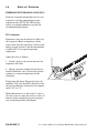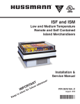
1
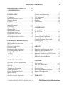
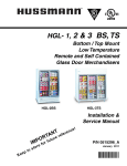
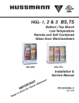
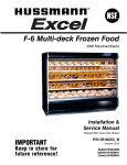
®
DDSS-4MC
Medium Temperature
Remote and Self Contained
Open Vertical Merchandisers
DDSS-4MC
NT refe
A
RT ture
O
IMPe for fu
s to
n
i
p
e
Ke
r
c
re n
e!
Installation &
Service Manual
P/N 0515957_E
February 2012
P/N0515957E
P/N 0515957_E
iii
IMPORTANT
KEEP IN STORE FOR FUTURE REFERENCE
Quality that sets industry standards!
®
12999 St. Charles Rock Road • Bridgeton, MO 63044-2483
U.S. & Canada 1-800-922-1919 • Mexico 01 800-890-2900
www.hussmann.com
© 2012 Hussmann Corporation
TABLE OF CONTENTS
v
BEFORE LOADING PRODUCT . . . . . . .iii
ANSI DEFINITIONS . . . . . . . . . . . . . . . . . vi
INSTALLATION
Certification . . . . . . . . . . . . . . . . . . . . . . . . 1-1
Hussmann Product Control . . . . . . . . . . . 1-1
Shipping Damage . . . . . . . . . . . . . . . . . . . 1-1
Location . . . . . . . . . . . . . . . . . . . . . . . . . . . 1-1
Self Contained (Location) . . . . . . . . . . . . 1-2
Model Description . . . . . . . . . . . . . . . . . . 1-3
Unloading . . . . . . . . . . . . . . . . . . . . . . . . . 1-3
Exterior Loading . . . . . . . . . . . . . . . . . . . . 1-3
Shipping Skid . . . . . . . . . . . . . . . . . . . . . . 1-3
Merchandiser Leveling . . . . . . . . . . . . . . . 1-4
Serial Plate Location . . . . . . . . . . . . . . . . . 1-4
Refrigeration Unit Access . . . . . . . . . . . . . 1-4
Casters . . . . . . . . . . . . . . . . . . . . . . . . . . . . 1-4
Sealing Merchandiser to Floor . . . . . . . . . 1-4
ELECTRICAL / REFRIGERATION
Merchandiser Electrical Data . . . . . . . . . . 2-1
Field Wiring . . . . . . . . . . . . . . . . . . . . . . . 2-1
Electrical Connections . . . . . . . . . . . . . . . 2-1
Electrical Outlet . . . . . . . . . . . . . . . . . . . . 2-1
Refrigeration (Self Contained) . . . . . . . . . 2-1
Line Sizing (Remote Models) . . . . . . . . . . 2-2
Koolgas (Remote Models) . . . . . . . . . . . . 2-2
Oil Traps . . . . . . . . . . . . . . . . . . . . . . . . . . . . . . . . . 2-2
Pressure Drop . . . . . . . . . . . . . . . . . . . . . . . . . . . . . 2-2
Water Outlet and Water Seal . . . . . . . . . . 2-2
Controls and Adjustments . . . . . . . . . . . . 3-7
Thermostatic Expansion Valve . . . . . . . . . 3-8
TEV Adjustment . . . . . . . . . . . . . . . . . . . . 3-8
Load Limits . . . . . . . . . . . . . . . . . . . . . . . . 3-9
Stocking . . . . . . . . . . . . . . . . . . . . . . . . . . . 3-9
Thermometer . . . . . . . . . . . . . . . . . . . . . . . 3-9
Notes . . . . . . . . . . . . . . . . . . . . . . . . . . . . 3-10
MAINTENANCE
Care and Cleaning . . . . . . . . . . . . . . . . . . . 4-1
Do NOT Use: . . . . . . . . . . . . . . . . . . . . . . 4-1
Do: . . . . . . . . . . . . . . . . . . . . . . . . . . . . . . . 4-1
Removing Scratches from Bumper . . . . . . 4-2
Cleaning Under Fan Plenum . . . . . . . . . . 4-2
Cleaning Stainless Steel Surfaces . . . . . . . 4-2
Cleaning Discharge Honeycomb . . . . . . . 4-3
Cleaning Coils . . . . . . . . . . . . . . . . . . . . . . 4-3
Cleaning Evaporation Pan . . . . . . . . . . . . 4-4
SERVICE
Replacing Fan Motors and Blades . . . . . . 5-1
Replacing Electronic Ballasts or
LED Power Supplies . . . . . . . . . . . . . . . . . 5-2
Replacing Fluorescent or LED Fixtures . 5-2
Repairing Aluminum Coil . . . . . . . . . . . . . 5-2
Replacing Electronic Ballasts . . . . . . . . . . 5-2
START UP / OPERATION
APPENDIX
Safe-NET III™ User Instructions . . . . . . 3-1
Display . . . . . . . . . . . . . . . . . . . . . . . . . . . . 3-2
Start-Up . . . . . . . . . . . . . . . . . . . . . . . . . . . 3-2
Sequence of Operation Diagram . . . . . . . 3-3
Temperature Adjustment . . . . . . . . . . . . . 3-4
Alarms and Codes . . . . . . . . . . . . . . . . . . . 3-4
Defrost Termination Switch . . . . . . . . . . . 3-4
Manual Defrost . . . . . . . . . . . . . . . . . . . . . 3-4
Temperature Adjustment . . . . . . . . . . . . . 3-5
Sensor to Control Adjustment . . . . . . . . . 3-6
HUSSMANN CORPORATION • BRIDGETON, MO 63044-2483 U.S.A.
Part Numbers . . . . . . . . . . . . . . . . . . . . . . A-1
Plan View DDSS-4MC . . . . . . . . . . . . . . . A-2
Cross Sections and Refrigeration Data . . A-3
Electrical Data . . . . . . . . . . . . . . . . . . . . . A-4
Self Contained Wiring Diagram . . . . . . . . A-5
Remote Wiring Diagram . . . . . . . . . . . . . A-6
WARRANTY
DDSS Open Vertical Merchandisers
vi
REVISION HISTORY
REVISION E — FEBRUARY 2012
1. Updated Wiring Diagrams
2. Updated Mexico phone number
**************************
ANSI Z535.5 DEFINITIONS
• DANGER – Indicate[s] a hazardous
situation which, if not avoided, will
result in death or serious injury.
REVISION D — JANUARY 2012
1. Removed DDSS-4 Model
2. Added new part numbers
3. Revised refrigeration data
4. Added LED replacement, Page 5-2
REVISION C — MAY 2011
1. Revised Cross Section Shelf Length, page A-4
REVISION B — OCTOBER 2010
1. Added self contained location drawings, page 1-2
2. Added Remote Line Sizing, Koolgas, page 2-2
3. Added Koolgas and Remote Refrigeration, page 2-9
4. Added TEV drawing and adjustment, page 3-8
5. Added Cleaning Precautions, page 4-4
6. Added dimension drawings & technical data,
pages, A-1, A-2
• WARNING – Indicate[s] a hazardous
situation which, if not avoided, could
result in death or serious injury.
• CAUTION – Indicate[s] a hazardous
situation which, if not avoided, could
result in minor or moderate injury.
• NOTICE – Not related to personal injury –
Indicates[s] situations, which if not avoided,
could result in damage to equipment.
ORIGINAL ISSUE — MARCH 2010
P/N 0515957_E
U.S. & Canada 1-800-922-1919 • Mexico 01-800-890-2900 • www.hussmann.com
P/N 0515957_E
1-1
INSTALLATION
CERTIFICATION
These merchandisers are manufactured to meet
ANSI / National Sanitation Foundation
(NSF® ) Standard #7 requirements. Proper
installation is required to maintain certification.
Near the serial plate, each case carries a label
identifying the type of application for which
the case was certified.
Apparent Loss or Damage
If there is an obvious loss or damage, it must
be noted on the freight bill or express receipt
and signed by the carrier’s agent; otherwise,
carrier may refuse claim.
Concealed Loss or Damage
ANSI/NSF-7 Type I - Display Refrigerator / Freezer
Intended for 75°F / 55% RH Ambient Application
ANSI/NSF-7 Type II - Display Refrigerator / Freezer
Intended for 80°F / 55% RH Ambient Application
When loss or damage is not apparent until
after equipment is uncrated, retain all packing
materials and submit a written response to the
carrier for inspection within 15 days.
ANSI/NSF-7 - Display Refrigerator
Intended for Bulk Produce
HUSSMANN PRODUCT CONTROL
The serial number and shipping date of all
equipment is recorded in Hussmann’s files for
warranty and replacement part purposes. All
correspondence pertaining to warranty or
parts ordering must include the serial number
of each piece of equipment involved. This is to
ensure the customer is provided with the correct
parts.
SHIPPING DAMAGE
All equipment should be thoroughly examined
for shipping damage before and during
unloading. This equipment has been carefully
inspected at our factory. Any claim for loss or
damage must be made to the carrier. The
carrier will provide any necessary inspection
reports and/or claim forms.
HUSSMANN CORPORATION • BRIDGETON, MO 63044-2483 U.S.A.
LOCATION
These merchandisers are designed for
displaying products in air conditioned stores
where temperature is maintained at or below
the ANSI / NSF-7 specified level and relative
humidity is maintained at or below 55%.
Recommended operating ambient
temperature is between
65°F (18°C) to 80°F (26.7°C).
Maximum relative humidity is 55%.
Placing refrigerated merchandisers in direct
sunlight, near hot tables or near other heat
sources could impair their efficiency. Like
other merchandisers, these merchandisers are
sensitive to air disturbances. Air currents
passing around merchandisers will seriously
impair their operation. Do NOT allow air
conditioning, electric fans, open doors or
windows, etc. to create air currents around the
merchandiser.
DDSS Open Vertical Merchandisers
1-2
INSTALLATION
SELF CONTAINED (LOCATION)
Product should always be maintained at proper
temperature. This means that from the time the
product is received, through storage, preparation
and display, the temperature of the product must
be controlled to maximize the life of the product.
BE SURE TO POSITION SELF CONTAINED
MERCHANDISERS PROPERLY.
SELF CONTAINED models have vented base
panels to allow air circulation through the
condensing unit.
Allow for a minimum 4 in. clearance from
walls, merchandisers, and any other large
objects near the merchandiser’s vented base
panels (for self contained models). Blocking or
restricting air flow will adversely affect performance and may damage the refrigeration system.
P/N 0515957_E
U.S. & Canada 1-800-922-1919 • Mexico 01 800-890-2900 • www.hussmann.com
P/N 0515957_E
1-3
MODEL DESCRIPTION
EXTERIOR LOADING
The DDSS models are open, vertical, medium
temperature display merchandisers. They are
available as either remote type, which require a
separate condensing unit connection, or self
contained. Each self contained model will have
its own condensing unit, factory installed
beneath the display area of the case ready for
operation when electrical service is connected.
Do NOT walk on top of merchandisers or
damage to the merchandisers and serious
personal injury could occur.
MERCHANDISERS ARE NOT STRUCTURALLY
DESIGNED TO SUPPORT EXCESSIVE EXTERNAL
such as the weight of a person. Do
not place heavy objects on the merchandiser.
LOADING
SHIPPING SKID
Do not walk or put heavy objects on case.
UNLOADING
Unloading from Trailer:
Lever Bar (also known as a Mule, Johnson
Bar, J-bar, Lever Dolly, or Pry Lever)
Move the merchandiser as close as possible to
its permanent location and remove all packaging.
Check for damage before discarding packaging.
Remove all separately packed accessories such
as kits and shelves.
Improper handling may cause damage to the
merchandiser when unloading. To avoid damage:
1. Do not drag the merchandiser out of the
trailer. Use a Johnson bar (mule).
2. Use a forklift or dolly to remove the
merchandiser from the trailer.
Each merchandiser is shipped on a skid to
protect the merchandiser’s base, and to make
positioning the case easier.
Remove the top of the crate and detach walls
from each other. Lift crate from the skid.
Unscrew the case from the skid. The fixture
can now be lifted off the crate skid. Lift only at
base of skid! Remove any braces and/or skids
attached (blanket wrapped merchandiser may
have skids).
DO NOT LAY MERCHANDISER OVER
ON THE FLOOR TO REMOVE SKID.
Once the skid is removed, the merchandiser
must be lifted —NOT PUSHED— to reposition.
To remove the skid, remove screws attaching
skid to the merchandiser.
Check floor where cases are to be set to see if
it is a level area. Determine the highest part of
the floor.
Do NOT remove shipping crate until the
merchandiser is positioned
HUSSMANN CORPORATION • BRIDGETON, MO 63044-2483 U.S.A.
DDSS Open Vertical Merchandisers
1-4
INSTALLATION
MERCHANDISER LEVELING
BE SURE TO POSITION MERCHANDISERS PROPERLY.
Level the merchandiser by all four corners.
Merchandiser(s) must be installed level to
ensure proper operation of the refrigeration
system, and to ensure proper drainage of
defrost water.
SERIAL PLATE LOCATION
The serial plate is located at the interior top
left end. It contains all pertinent information
such as model, serial number, amperage rating,
refrigerant type and charge.
CASTERS
The merchandiser may be equipped with
optional casters. If the merchandiser has
optional casters as shown below, use the brake
to lock the merchandiser in place.
Serial Plate
REFRIGERATION UNIT ACCESS
The lower front panel may be removed by
lifting the panel straight upward and over the
tabs on which it is hanging. In a self contained
merchandiser, two screws will have to be
removed from either end of the panel. The
panel is installed by reversing the above procedure. Ensure lower front panel is flat against
the floor when installed to prevent air circulation
problems on self contained merchandisers.
SEALING MERCHANDISER TO FLOOR
If required by local sanitary codes, or if the
customer desires, merchandisers may be sealed
to the floor using a vinyl cove base trim. The
size needed will depend on how much variation
there is in the floor, from one end of the
merchandiser to the other. Sealing of the lower
front and rear panels on self contained models
may hamper their removal for servicing or
maintenance of the condensing unit.
NOTE: Do not allow trim to cover any intake
or discharge grilles located in the lower front
panel.
P/N 0515957_E
U.S. & Canada 1-800-922-1919 • Mexico 01 800-890-2900 • www.hussmann.com
P/N 0515957_E
2-1
ELECTRICAL / REFRIGERATION
MERCHANDISER ELECTRICAL DATA
Refer to merchandiser serial plate for electrical
information.
FIELD WIRING
Field wiring must be sized for component
amperes stamped on the serial plate. Actual
ampere draw may be less than specified.
ALWAYS CHECK THE SERIAL PLATE FOR
COMPONENT AMPERES
— LOCK OUT / TAG OUT —
To avoid serious injury or death from electrical
shock, always disconnect the electrical power
at the main disconnect when servicing or
replacing any electrical component. This
includes, but is not limited to, such items as
doors, lights, fans, heaters, and thermostats.
Self-contained models have
factory-installed power cords
attached at the electrical box.
ELECTRICAL CONNECTIONS
All wiring must be in compliance with NEC
and local codes. All electrical connections (for
remote models) are to be made in the electrical
Handy Box located behind the removable base
panel at the left end of the merchandiser when
facing the discharge honeycomb.
ELECTRICAL OUTLET:
Before the merchandiser is connected to any
wall circuit, use a voltmeter to check that the
outlet is at 100% of the rated voltage. The wall
circuit must be dedicated for the merchandiser.
Failure to do so voids the warranty. Do not use
an extension cord. Never plug in more than one
merchandiser per electrical circuit.
• Always use a dedicated circuit with the
amperage stated on the unit.
• Plug into an outlet designed for the plug.
• Do not overload the circuit
• Do not use long or thin extension cords.
Never use adapters.
• If in doubt, call an electrician.
HUSSMANN CORPORATION • BRIDGETON, MO 63044-2483 U.S.A.
REFRIGERATION
(Self Contained Models)
Each self contained model is equipped with
its own condensing unit and control panel
located beneath the display area. The correct
type of refrigerant will be stamped on each
merchandiser’s serial plate. The merchandiser
refrigeration piping is leak tested. The unit is
charged with refrigerant, and shipped from
the factory with all service valves open.
Risk of Electric Shock. If cord or plug
becomes damaged, replace only with
a cord and plug of the same type.
Merchandiser must be grounded.
Do not remove the power supply cord ground.
DDSS Open Vertical Merchandisers
2-2
INSTALLATION
LINE SIZING
(Remote Models)
Refrigerant line connections are made at the
right end of merchandiser (facing front)
beneath the refrigerated display area. The
refrigerant line connection size is 3/8 in. The
suction line is 5/8 in. Refrigerant lines should be
sized as shown on the refrigeration legend that
is furnished for the store or according to
ASHRAE guidelines.
Refrigeration lines are under pressure.
Refrigerant must be recovered before
attempting any connection or repair.
For refrigerators with other than Koolgas
defrost, the suction and liquid line should be
clamped and/or taped together and insulated
for a minimum of 30 feet from the refrigerator.
KOOLGAS
(Remote Models)
If Koolgas defrost is used, the liquid line will
need to be increased two sizes larger inside the
merchandiser area. This is necessary to ensure
even liquid drainage from all evaporators during
defrost. Refrigerators with Koolgas defrost
SHOULD NOT have their liquid lines and suction
lines in contact with each other but are to be
separately insulated for a minimum of 30 ft
from the refrigerator. Additional information
for the balance of the refrigerant lines is recommended and required wherever condensation and
dripping would be objectionable.
Oil Traps
P-traps (oil traps) must be installed at the base
of all suction line vertical risers.
P/N 0515957_E
Pressure Drop
Keep refrigerant line runs as short as possible
to avoid large pressure drops. Use a minimum
number of elbows. Where elbows are required,
USE LONG RADIUS ELBOWS ONLY.
When brazing pipes, be sure to use the
insulation blanket shipped with the
merchandiser to prevent damage to the
metal merchandiser bottom.
WATER OUTLET AND WATER SEAL
The condensate water outlet is located in the
center of the merchandiser. The outlet has an
external water seal installed from the factory.
For self contained and remote models, this
water seal drains into the condensate evaporation pan located beneath the merchandiser.
Remote models have a fan to circulate air
around the base to keep condensation from
forming.
NOTE: All lower base panels must be in place
when the refrigerator is operating. If not, airflow from the condenser (self-contained) will
be directed over the evaporation pan and
defrost water in the pan may overflow.
Product will be degraded and may spoil if
allowed to sit in a non-refrigerated area.
U.S. & Canada 1-800-922-1919 • Mexico 01-800-890-2900 • www.hussmann.com
P/N 0515957_E
3-1
START UP / OPERATION
INSTALLER
It is the contractor’s responsibility to
install merchandiser(s) in accordance with
all local building and health codes.
The Safe-NET III controller includes the
following features and connections.
• Adjustment knob:
Adjusts the temperature setpoint.
Turn adjustment knob to OFF to turn off
refrigeration system. Unplug merchandiser
from power before servicing the unit.
Safe-NET III™
TEMPERATURE AND DEFROST
CONTROLLER
SAFE-NET III™ USER INSTRUCTIONS
Your refrigerated case uses a Hussmann
Safe-NET™ III temperature and defrost
controller to precisely maintain the temperature and prevent frost buildup on the cooling
coil. LEDs indicate when the compressor or
refrigeration is on, when the case is in a defrost
cycle, if the temperature is outside the desired
range, or if there is a sensor failure.
An adjustment knob allows the temperature to
be set within the configured range and can
power off the controller and compressor. Your
controller has been custom-configured to provide the best temperature and defrost control
for your chilled or frozen food.
• Controller LEDs:
Compressor Powered On LED (green):
Lights while the compressor is running or
the refrigeration valve is open.
Defrost Cycle LED (yellow):
Lights while the refrigeration coil is
defrosting.
Temperature or Sensor Alarm (red):
Lights if the temperature is too warm or
too cold. Flashes if a sensor fails.
The front of the controller has an adjustment
knob and status LEDs. The back of the
controller has connections for sensors and
switched equipment.
HUSSMANN CORPORATION • BRIDGETON, MO 63044-2483 U.S.A.
DDSS Open Vertical Merchandisers
3-2
START
UP
/ OPERATION
• Rear connections:
– Case temperature sensor:
• Typically senses the temperature
of the air in the case.
Used by the controller to determine when
to power on or power off the compressor
or refrigeration.
– Evaporator temperature sensor:
• Senses the temperature of the
refrigeration coil.
Terminates a defrost cycle when
refrigeration coil ice melts.
– Compressor or refrigeration relay:
• Switches on the compressor or
refrigeration valve for cooling.
START-UP
1. Plug in the merchandiser.
The OFF Position does not disconnect line
voltage to the case, refrigeration unit, fan,
or heater.
DISPLAY
2. Wait for the self check to complete. During
the self check, each LED flashes for one
second, then all LEDs turn on for two
seconds. If the LEDs do not flash, make
sure the adjustment knob is not in the Off
position.
• After the self check, all LEDs turn off
until the compressor starts. There may be a
delay before the compressor starts. If the
red Temperature or Sensor Alarm LED
stays on after the self check.
• The green Compressor Powered On LED
turns on when the compressor starts.
The display includes three red LEDs and two
digits for temperature, defrost status, and error
codes.
NOTE: Do NOT load product until AFTER
merchandiser operates for 24 hours and reaches
desired operating temperature.
The optional evaporator fan remains ON
when the adjustment knob is in the OFF
position.
The three display LEDs are red, and their
behavior matches the LEDs on the controller.
Product will be degraded and may spoil if
allowed to sit in a non-refrigerated area.
P/N 0515957_E
U.S. & Canada 1-800-922-1919 • Mexico 01 800-890-2900 • www.hussmann.com
P/N 0515957_E
1. Apply power to the merchandiser. Wait for
the self check to complete. During the self
check, each LED flashes for one second and
then all LEDs turn on for two seconds. If the
LEDs do not flash, make sure the adjustment
knob is not in the “OFF” position.
1A. The merchandiser temperature displays at
startup. The initial defrost starts two hours
later. The display will show the temperature at
the start of defrost. This reading will remain
displayed during defrost and until it times out,
even though the refrigeration mode has been
initiated. (The green LED will be lit.)
3-3
3. The compressor will continue to run until it
reaches its cut-out temperature (Pulldown).
4. The refrigeration cycle will continue for the next
subsequent scheduled (6-hours) or demand
defrost. The digital display will display the
temperature reading for 10 minutes after
defrost.
5. The above process will repeat (steps 3 and 4)
until the power is interrupted.
6. If power stops, the process will start over at step
1, and the time to subsequent defrost will reset.
2. The compressor will start after a 1-minute delay
once power is applied.
HUSSMANN CORPORATION • BRIDGETON, MO 63044-2483 U.S.A.
DDSS Open Vertical Merchandisers
3-4
START
UP
/ OPERATION
TEMPERATURE ADJUSTMENT
DEFROST TERMINATION SWITCH
Rotate the adjustment knob counter clockwise
for a warmer setpoint or clockwise for a colder
setpoint.
• While the temperature is being adjusted,
the optional display shows the setpoint (cut
out value). A few seconds after the temperature is set, the display reverts to showing
the sensed temperature in the merchandiser.
Merchandisers may use a defrost termination
switch, instead of an evaporator sensor to
terminate a defrost cycle. The defrost
termination switch is temperature activated
and senses the completion of defrost.
ALARMS AND CODES
FLASHING TEMPERATURE OR SENSOR ALARM
LED, E1 OR E2
If the Temperature or Sensor Alarm LED
(red) on the controller and display is flashing,
a temperature sensor has failed. The display
shows E1 if the case sensor has failed or E2 if
the evaporator sensor has failed.
MANUAL DEFROST
Note:
This procedure initiates
a manual or forced
defrost.
If the merchandiser sensor fails, refrigeration
will run continuously. Turn off, or repeat a
duty cycle of a few minutes on and a few
minutes off.
IMPORTANT: Return the control knob to its
original setting (Step 1) once the manual
defrost has been initiated.
P/N 0515957_E
U.S. & Canada 1-800-922-1919 • Mexico 01 800-890-2900 • www.hussmann.com
P/N 0515957_E
3-5
TEMPERATURE ADJUSTMENT
1. Rotate the adjustment knob counter clockwise for a warmer setpoint or clockwise for
a colder setpoint.
3. To verify merchandiser settings, turn the
dial to warm and cold as shown above.
Output readings should be within one
degree of the temperatures shown above.
2. While adjusting the temperature, the display
shows the setpoint (cut out value). A few
seconds after the temperature is set, the
controller reverts to the sensed temperature
in the merchandiser.
HUSSMANN CORPORATION • BRIDGETON, MO 63044-2483 U.S.A.
DDSS Open Vertical Merchandisers
3-6
START
P/N 0515957_E
UP
/ OPERATION
U.S. & Canada 1-800-922-1919 • Mexico 01 800-890-2900 • www.hussmann.com
P/N 0515957_E
1. The Safe-NET III Controller controls refrigeration temperature. This is factory installed in
the control panel. Adjust this control knob to
maintain the discharge air temperature shown.
Measure discharge air temperatures at the
center of the honeycomb.
HUSSMANN CORPORATION • BRIDGETON, MO 63044-2483 U.S.A.
3-7
Defrosts are time initiated and temperature
terminated for self contained and remote,
including Koolgas models. The defrost setting
is factory set as shown above.
To ensure a thorough defrost, defrost must be
terminated by the temperature termination
setting — not by time.
DDSS Open Vertical Merchandisers
3-8
START
UP
/ OPERATION
THERMOSTATIC EXPANSION VALVE (TEV)
Each self contained merchandiser has its own
evaporator coil and a pre-set thermostatic
expansion valve (TEV). The TEV has been
factory set at design conditions to provide the
recommended performance.
TEV Adjustment
Expansion valves may be adjusted to fully feed
the evaporator. Before attempting to adjust
valves, make sure the evaporator is clear or only
lightly covered with frost, and the merchandiser
is within 10°F of its expected operating
temperature.
Adjust the valve as Follows:
a. Attach a probe to the suction line near the
expansion valve bulb.
b. Obtain a pressure reading from the factory
installed Schraeder valve. Convert the pressure
reading to a saturated temperature for the
refrigerant.
Temperature (b) minus Temperature (a) is the
superheat. The valve should be adjusted so that
the greatest difference between the two temperatures is 3°F to 5° F.
Probe Locations
Make adjustments of no more than 1/2 turn of
the valve stem at a time and wait for at least 15
minutes before rechecking the probe temperature and making further adjustments.
P/N 0515957_E
U.S. & Canada 1-800-922-1919 • Mexico 01 800-890-2900 • www.hussmann.com
P/N 0515957_E
3-9
LOAD LIMITS
Each merchandiser has a load limit decal. Shelf
life of perishables will be short if load limit is
violated.
AT NO TIME SHOULD MERCHANDISERS BE
STOCKED BEYOND THE LOAD LIMITS INDICATED.
DO NOT BLOCK HONEYCOMB.
Product will be degraded and may spoil if
allowed to sit in a non-refrigerated area.
THERMOMETER
DDSS models have a 1-in. thermometer. The
thermometer is located at the top, interior of
the merchandiser.
STOCKING
Product should NOT be placed inside the
merchandisers until merchandisers are at
proper operating temperature.
Allow merchandiser 24 hours to operate before
loading product.
Proper rotation of product during stocking is
necessary to prevent product loss. Always bring
the oldest product to the front and set the
newest to the back.
AIR DISCHARGE AND RETURN FLUES MUST
REMAIN OPEN AND FREE OF OBSTRUCTION AT
to provide proper refrigeration and
air curtain performance. Do not allow product,
packages, signs, etc. to block these grilles. Do
not use non-approved shelving, baskets,
display racks, or any accessory that could
hamper air curtain performance.
ALL TIMES
Do not allow product to be placed outside of
the designated load limits in the illustration.
HUSSMANN CORPORATION • BRIDGETON, MO 63044-2483 U.S.A.
LOAD LIMIT
DDSS Open Vertical Merchandisers
3-10
START
UP
/ OPERATION
NOTES:
P/N 0515957_E
U.S. & Canada 1-800-922-1919 • Mexico 01 800-890-2900 • www.hussmann.com
P/N 0515957_E
4-1
MAINTENANCE
CARE AND CLEANING
Do:
Long life and satisfactory performance of any
equipment is dependent upon the care it
receives. To ensure long life, proper sanitation
and minimum maintenance costs, these
merchandisers should be thoroughly cleaned,
all debris removed and the interiors washed
down, weekly.
•Remove the product and all loose debris to
avoid clogging the waste outlet.
Exterior Surfaces
The exterior surfaces must be cleaned with a
mild detergent and warm water to protect and
maintain their attractive finish. NEVER USE
ABRASIVE CLEANSERS OR SCOURING PADS.
Interior Surfaces
The interior surfaces may be cleaned with most
domestic detergents, ammonia based cleaners
and sanitizing solutions with no harm to the
surface. Self contained models empty into a
limited capacity evaporation pan, which will
overflow if excess water is used in cleaning.
•Store product in a refrigerated area such as a
cooler. Remove only as much product as can
be taken to the cooler in a timely manner.
•Disconnect electrical power before cleaning.
•Thoroughly clean all surfaces with soap and
hot water. DO NOT USE STEAM OR HIGH WATER
PRESSURE HOSES TO WASH THE INTERIOR. THESE
WILL DESTROY THE MERCHANDISERS’ SEALING
CAUSING LEAKS AND POOR PERFORMANCE.
•Take care to minimize direct contact between
fan motors and cleaning or rinse water.
•Do NOT flood merchandiser with water.
NEVER INTRODUCE WATER FASTER THAN THE
WASTE OUTLET CAN REMOVE IT.
Do NOT Use:
•Abrasive cleansers and scouring pads, as these
will mar the finish.
Do NOT allow cleaning agent or
cloth to contact food product.
•Coarse paper towels on coated glass.
•Ammonia-based cleaners on acrylic parts.
•Solvent, oil or acidic based cleaners on any
interior surfaces.
•Do not use high pressure water hoses.
SELF CONTAINED MODELS EMPTY INTO A
CONDENSATE EVAPORATION PAN THAT WILL
OVERFLOW IF TOO MUCH WATER IS INTRODUCED
DURING CLEANING.
•Allow merchandisers to dry before resuming
operation.
•After cleaning is completed, turn on power to
the merchandiser.
Product will be degraded and may spoil if
allowed to sit in a non-refrigerated area.
HUSSMANN CORPORATION • BRIDGETON, MO 63044-2483 U.S.A.
DDSS Open Vertical Merchandisers
4-2
MAINTENANCE
Do NOT use HOT water on Cold glass Surfaces.
This can cause the glass to shatter and could
result in personal injury. Allow glass fronts, to
warm before applying hot water.
SHUT FANS OFF DURING
CLEANING PROCESS.
REMOVING SCRATCHES FROM BUMPER
Most scratches and dings can be removed
using the following procedure.
1. Use steel wool to smooth out the surface
area of the bumper.
2. Clean area.
3. Apply vinyl or car wax and polish surface
for a smooth glossy finish.
DO NOT FLOOD!
CLEANING UNDER FAN PLENUM
To facilitate cleaning, the fan plenum is hinged.
After cleaning be sure the plenum is properly
lowered into position OR PRODUCT LOSS WILL
RESULT due to improper refrigeration.
Use only enough water necessary to clean
surface. Water must not drip down the case!
Never use ammonia based cleansers, abrasive
cleansers, or scouring pads.
CLEANING STAINLESS STEEL SURFACES
— LOCK OUT / TAG OUT —
To avoid serious injury or death from electrical shock,
always disconnect the electrical power at the main disconnect when servicing or replacing any electrical component. This includes, but is not limited to, such items
as doors, lights, fans, heaters, and thermostats.
P/N 0515957_E
Use non-abrasive cleaning materials, and
always polish with grain of the steel. Use warm
water or add a mild detergent to the water and
apply with a cloth. Always wipe rails dry after
wetting.
Use alkaline chlorinated or non-chlorine
containing cleaners such as window cleaners
and mild detergents. Do not use cleaners
containing salts as this may cause pitting and
rusting of the stainless steel finish. Do not use
bleach.
U.S. & Canada 1-800-922-1919 • Mexico 01 800-890-2900 • www.hussmann.com
P/N 0515957_E
4-3
CLEANING DISCHARGE HONEYCOMB
CLEANING COILS
Discharge air honeycomb should be cleaned
every six months. Dirty honeycomb will
cause merchandisers to perform poorly.
The honeycomb may be cleaned with a vacuum
cleaner. Soap and water may be used if all
water is removed from the honeycomb cells
before replacing. Be careful not to damage the
honeycomb.
Condenser coils should be cleaned at least once
per month. Additional cleaning may be needed
depending on the operational environment. A
dirty condenser blocks normal airflow through
the coils.
1. Using a flat object such as a screw driver,
behind the rear edge of the honeycomb on
on the right hand end, and gently pull
down.
2. Clean with a mild detergent and warm
water and dry the honeycomb.
3. After cleaning, replace in reverse order.
Damaged honeycomb must be replaced.
Airflow blockage increases energy consumption
and reduces the merchandiser’s ability to maintain operating temperature.
To clean the coils, use a vacuum cleaner with a
wand attachment and a soft (non-metallic)
brush to remove dirt and debris. Do not bend
coil fins. Always wear gloves and protective eye
wear when cleaning near sharp coil fins and
dust particles.
HUSSMANN CORPORATION • BRIDGETON, MO 63044-2483 U.S.A.
DDSS Open Vertical Merchandisers
4-4
MAINTENANCE
CLEANING EVAPORATION PAN
The condensate water outlet empties into a
limited capacity evaporation pan.
Debris or dirt accumulation inside the condensate
evaporation pan or on the heater coil will
reduce the pan’s evaporation capacity and
cause premature heater failure. The evaporation
pan waste water will overflow and spill onto the
floor if the heater is not properly operating.
Evaporation Pan is Hot!
and poses risk of bodily injury – Always Wear gloves
and protective eye wear when servicing. Turn off
evaporation pan heater, and allow pan to cool.
Remove accumulated debris from the evaporation pan. Wipe down heater coil with a cloth
and warm water. Be sure to remove any dirt,
debris or liquids from the heater coil.
Water introduced during cleaning will cause
the evaporation pan to overflow.
P/N 0515957_E
U.S. & Canada 1-800-922-1919 • Mexico 01 800-890-2900 • www.hussmann.com
P/N 0515957_E
5-1
SERVICE
REPLACING FAN MOTORS AND BLADES
Should it ever be necessary to service or
replace the fan motors or blades be certain
that the fan blades are reinstalled correctly.
THE BLADES MUST BE INSTALLED WITH RAISED
EMBOSSING (PART NUMBER ON PLASTIC BLADES)
POSITIONED AS INDICATED ON THE PARTS LIST.
For access to these fans:
1. Remove product and place in a refrigerated
area. Turn off power to the merchandiser.
2. Remove bottom display pans.
3. Disconnect fan from wiring harness.
4. Remove fan blade.
5. Lift fan plenum and remove screws holding bottom of motor to fan basket.
— LOCK OUT / TAG OUT —
To avoid serious injury or death from electrical
shock, always disconnect the electrical power
at the main disconnect when servicing or
replacing any electrical component. This
includes, but is not limited to, such items as
doors, lights, fans, heaters, and thermostats.
11. Close air gaps under fan plenum. Warmer
air moving into refrigerated air reduces
effective cooling. If the plenum does not
rest against the case bottom without gaps,
apply foam tape to the bottom of the fan
plenum to reduce improper air movement.
Use silicone sealant to close other gaps.
12. Reinstall display pans. Bring merchandiser
to operating temperature before restocking.
6. Replace fan motor and blade.
7. Lower fan plenum.
8. Reconnect fan to wiring harness.
9. Turn on power.
10. Verify that motor is working and blade is
turning in the correct direction.
Product will be degraded and may spoil if
allowed to sit in a non-refrigerated area.
Note: Plenum length
and number of fans will
vary with model.
HUSSMANN CORPORATION • BRIDGETON, MO 63044-2483 U.S.A.
DDSS Open Vertical Merchandisers
5-2
SERVICE
REPLACING ELECTRONIC BALLASTS
OR LED POWER SUPPLIES
The canopy ballast or LED power supply is
located in the electrical box on top of the
merchandiser.
To gain access:
1. DISCONNECT THE ELECTRICAL POWER TO
THE MERCHANDISER.
2. Remove screws attaching the wireway cover,
then remove cover.
3. Service or replace ballast / LED power
supply as required. Reassemble items as
they were originally installed.
4. Reconnect the electrical power.
REPLACING FLUORESCENT LAMPS
OR LED FIXTURES
Fluorescent lamps have a plastic shield. When
the lamp is replaced, keep the lamp shield to
install over the new lamp.
LED Fixtures have the protective shield incorporated. Remove fluorescent fixtures the same
way as fluorescent bulbs.
The switch under the display lamp cover operates both the display lamp and interior lamps.
Fluorescent lamps contain mercury vapor.
Mercury exposure at high levels can harm
the brain, heart, kidneys, lungs, and immune
system of people of all ages. Do not break or
puncture fluorescent lamps. Dispose of, or
store, all fluorescent lamps in accordance
with Federal (40 CFR 273), State, and local
hazardous waste requirements. Refer to
http://www.epa.gov/mercury/about.htm
P/N 0515957_E
Remove Plastic Pins Attaching Display Lamp
REPAIRING ALUMINUM COIL
The aluminum coils used in Hussmann merchandisers may be easily repaired in the field.
Materials are available from local refrigeration
wholesalers.
NOTE:
Hussmann Aluminum melts at1125°F (607°C)
Aladdin 3-in-1 rod at
732°F (389°C)
X-Ergon Acid core at
455°F (235°C)
Technique:
1.
2.
3.
4.
Locate Leak.
REMOVE ALL PRESSURE.
Brush area UNDER HEAT.
Use PRESTOLITE TORCH ONLY.
Number 6 tip.
5. Maintain separate set of stainless steel
brushes, and USE ONLY ON ALUMINUM.
6. Tin surface around area.
7. Brush tinned surface UNDER HEAT,
thoroughly filling the open pores around
leak.
8. Repair leak. Let aluminum melt solder,
NOT the torch.
9. Don't repair for looks. Go for thickness.
10. Perform a leak check.
11. Wash with water.
12. Cover with a good flexible sealant.
U.S. & Canada 1-800-922-1919 • Mexico 01-800-890-2900 • www.hussmann.com
APPENDIX A — TECHNICAL DATA
A-1
Hussmann refrigerated merchandisers configured for sale for use in the United States meet or
surpass the requirements of the DOE 2012 energy efficiency standards.
Item
Part #
Description
FAN ASSEMBLIES AND THERMOSTATS
12W Standard Fan Assembly
MO.4410327 Fan Assembly - 208V/230V
FB.0142780
Item
Part #
Description
C ONTROL PANEL
SW.4440546
Disconnect Switch 25 Amps
RL.4441382
Compressor Relay
RL.4480237
Condensate Pan Heater
Relay
EP.4441442
Power Cord 6-20P
Fan Blade
CT.4483049
Safe Net III Controller
CC.4482991
Defrost Sensor (Yellow)
CC.4482992
Air Sensor (Black) SS TIP
CC.4482540
Safe Net III Display (ºF)
CU.4200819 Compressor - 220V / 60hz
EP.4482541
Safe Net III Harness
BR.4916662
Condenser Motor 16W,
(208V - 230V)
FB.4780650
Condenser Fan Blade
10 in. 31º pitch
MO.4410327 12 W Energy Efficient Fan
Assembly
CO.4613825
Condenser
FB.0142780
FI.4916098
Drier
VR.4613896
Expansion Valve
Remote Cases
Fan Blade fu800cw25s
MO.4411*-064
4W Exhaust Fan
R EFRIGERATION
L AMPS
HEATERS
AND
BALLASTS
HE.4851189
Condensate Pan Heater
(208V - 230V)
BA.4480870 Ballast Lamp - (2 Lamps)
DP.4918934
Condensate Pan
Fluorescent Lamps:
Replace with Like Fixtures
FL.4916870
Floating Switch
SW.4440541 Light, Lgt
LED O PTION
HUSSMANN CORPORATION • BRIDGETON, MO 63044-2483 U.S.A.
EP.4483187
Power Supply
BU.441800
LED Fixture
DDSS Open Vertical Merchandisers
A-2
APPENDIX A — TECHNICAL DATA
DDSS-4MC
General
Case Length (Note: Includes One Pair Ends)
Maximum O/S dimension of case back to front
(Note: Includes bumper)
4ft (51) (1295)
30 1/2 (775)
Waste Outlet
RH end of case (from outside of End Assembly)
to center of waste outlet
25 1/2 (648)
P/N 0515957_E
U.S. & Canada 1-800-922-1919 • Mexico 01-800-890-2900 • www.hussmann.com
APPENDIX A — TECHNICAL DATA
A-3
Dimensions shown as inches and (mm).
REFRIGERATION DATA
DDSS-4MC
Note: This data is based on store temperature
and humidity that does not exceed 80°F
and 55% R.H. unless otherwise stated.
Schedule defrost at night while lights are
off.
DDSS-4MC
Thermostat
Setting CI/CO (°F)
Position #1 34 / 31
position #7 34 / 14
Condensing Unit (hp)
1
Condensing Unit
Capacity
(Btu/hr at std. rating
conditions)
9992
DEFROST DATA
Frequency (hr)
6
OFFTIME
Failsafe (minutes)
40
Defrost Termination
Pressure (psig)
45°F
PHYSICAL DATA
Refrigerant Charge
DDSS-4MC
HUSSMANN CORPORATION • BRIDGETON, MO 63044-2483 U.S.A.
44 oz
1.248 kg
DDSS Open Vertical Merchandisers
A-4
APPENDIX A — TECHNICAL DATA
Electrical Data
Note: These are rated values for individual components and should not be added together to
determine total merchandiser electrical load.
DDSS-4MC
1
Number of Fans – 12W
Self-Contained
Amperes
Watts
0.33
50
Evaporator Fans
230V 60Hz Standard 0.33
Condensate Pan Heaters (230V)
3.8
Remote
Amperes
Watts
0.12
18
750
3.8
750
Condensing Unit (208/230V, 1Ph, 60Hz) Standard — Self-Contained
Compressor LRA
33.7
Compressor RLA
6.8
Minimum Circuit Ampacity — Self-Contained
230V 1Ph
60HZ
Standard
230V 1PH
60HZ
Energy Efficient
Maximum Over Circuit Protection 208/230V — Self-Contained
10.85
10.67
20
Maximum Circuit Ampacity — Remote
230V 1Ph
60HZ
Standard
Maximum Over Circuit Protection 208/230V — Remote
4.65
15
DDSS-4 / DDSS4MC
AHRI Total Display Area 1 (Sq Ft/Case)
13.01 ft2 /case ( 1.21 m2 /case)
Computed using AHRI 1200 standard methodology:
Total Display Area, ft2 [m2] / Unit of Length, ft [m]
1
ESTIMATED SHIPPING WEIGHT 2
Case
Self Contained
900 ( 408 )
lb (kg)
2
P/N 0515957_E
Remote
850 ( 386 )
End
Included
Actual weights will vary according to optional kits included.
U.S. & Canada 1-800-922-1919 • Mexico 01-800-890-2900 • www.hussmann.com
APPENDIX A — TECHNICAL DATA
A-5
DDSS-4MC — Self Contained
HUSSMANN CORPORATION • BRIDGETON, MO 63044-2483 U.S.A.
DDSS Open Vertical Merchandisers
A-6
APPENDIX A — WIRING DIAGRAMS
DDSS-4MCR — Remote
Connect to solenoid valve
or condensing unit.
P/N 0515957_E
U.S. & Canada 1-800-922-1919 • Mexico 01-800-890-2900 • www.hussmann.com
®
To obtain warranty information
or other support, contact your
Hussmann representative.
Please include the model and
serial number of the product.
Hussmann Corporation, Corporate Headquarters: Bridgeton, Missouri, U.S.A. 63044-2483 01 September 2011
Hussmann Corporation
12999 St. Charles Rock Road
Bridgeton, MO 63044
www.hussmann.com