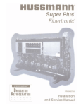
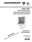
1
Contents
®
Tables
Figures
Scroll Plus
™
Fibertronic
™
®
P/N 401789
Installation and
Service Manual
Contents
Revised August 1, 1996
Tables
Figures
SAFETY TIPS
Being Safe is Your Responsibility.
Wear proper eye protection whenever working.
Wear proper hearing protection whenever
working in a machine room.
Know whether a circuit is open at the power
supply or not. Remove all power before
opening control panels.
Always supply proper ventilation.
•Refrigerants and nitrogen can displace oxygen
causing suffocation.
Stand to one side–never work directly in
front of:
•Any valve you are opening or closing
Manual refrigeration valves
Regulator valves on brazing tanks and
nitrogen tanks
•Electrical
•Refrigerants
exposed to flame can produce
phosgene, a poisonous gas.
Be sure refrigeration lines are free of pressure
before cutting. Check:
•Both sides of a two way valve
Circuit Breakers
•All
•Refrigeration
lines to a 3-way or 4-way valve
lines you are cutting or opening
Always use a pressure regulator with a nitrogen tank.
•Do not exceed 2 pounds of pressure and
vent lines when brazing.
Dangerous hydraulic explosions may result if
you
•Isolate liquid lines or compressor when they
can absorb heat over an extended time period
•Overfill
pumpdown refrigerant containers
•Do
not exceed 350 pounds of pressure for
leak testing high side.
•Do not exceed 150 pounds of pressure for
leak testing low side.
Use only a striker to light torch.
Never vent refrigerants
into the atmosphere.
Contents
Tables
Figures
®
Hussmann Corporation
12999 St. Charles Rock Road
Bridgeton, Missouri 63044-2483
(314) 291-2000
Congratulations!
With the purchase of Hussmann's Scroll Plus™ Fibertronic™ System, you are
receiving equipment designed to provide the finest refrigeration and temperature
control for modern supermarket display equipment and coolers.
Since the introduction of Hussmann Central Refrigeration Systems, thousands of
installations have confirmed our belief that, as with all fine equipment, good
installation and proper adjustment are the keys to customer satisfaction.
The information presented in this manual includes many details resulting from
our experience over many years. Its use will guide the contractor to a successful
installation. Time taken to read and to understand this information will pay off in
reducing lost time and duplication work.
Should there be questions concerning this information, do not hesitate to write
me. Your inquiry will be welcomed.
George Ballinger
Manager of Field Service
970901
Contents
®
®
Tables
Figures
Scroll Plus™
Fibertronic™
Installation and
Service Manual
Hussmann Corporation
12999 St. Charles Rock Road
Bridgeton, MO 63044-2483
Printed in USA
®
P/N 401789
September, 1997
Figures
Tables
Scroll Plus™ Fibertronic™
Installation and Service Manual
Contents
Installation Instructions - - - - - - - - - - - - - - - - - - - - - - - - - - - - - - - - - - - - - - - - - - - - - - - 1-1
Overview - - - - - - - - - - - - - - - - - - - - - - - - - - - - - - - - - - - - - - - - - - - - - - - - - - - - - - - - - - -1-1
Scroll Plus™ Components - - - - - - - - - - - - - - - - - - - - - - - - - - - - - - - - - - - - - - - - - - - - - - - 1-2
Shipping Damage - - - - - - - - - - - - - - - - - - - - - - - - - - - - - - - - - - - - - - - - - - - - - - - - - - - - 1-2
Scroll Plus Frame Dimensions - - - - - - - - - - - - - - - - - - - - - - - - - - - - - - - - - - - - - - - - - - - - -1-2
System Weights - - - - - - - - - - - - - - - - - - - - - - - - - - - - - - - - - - - - - - - - - - - - - - - - - - - - - - 1-2
Receiver Refrigerant Capacities - - - - - - - - - - - - - - - - - - - - - - - - - - - - - - - - - - - - - - - - - - - 1-2
Machine Room Requirements - - - - - - - - - - - - - - - - - - - - - - - - - - - - - - - - - - - - - - - - - - - - 1-3
Scroll Plus Load Points - - - - - - - - - - - - - - - - - - - - - - - - - - - - - - - - - - - - - - - - - - - - - - - - - 1-3
Unit Placement - - - - - - - - - - - - - - - - - - - - - - - - - - - - - - - - - - - - - - - - - - - - - - - - - - - - - - -1-3
Lifting and Leveling - - - - - - - - - - - - - - - - - - - - - - - - - - - - - - - - - - - - - - - - - - - - - - - - - - - 1-5
Setting Without a Crane - - - - - - - - - - - - - - - - - - - - - - - - - - - - - - - - - - - - - - - - - - - - - - - - 1-5
Scroll Plus Refrigeration Process - - - - - - - - - - - - - - - - - - - - - - - - - - - - - - - - - - - - - - - 2-1
Oveview - - - - - - - - - - - - - - - - - - - - - - - - - - - - - - - - - - - - - - - - - - - - - - - - - - - - - - - - - - - 2-1
Scroll Plus Fibertronic Refrigeration System - - - - - - - - - - - - - - - - - - - - - - - - - - - - - - - - - - - 2-2
Basic Refrigeration Cycle - - - - - - - - - - - - - - - - - - - - - - - - - - - - - - - - - - - - - - - - - - - - - - - 2-4
Heat Reclaim Cycle - - - - - - - - - - - - - - - - - - - - - - - - - - - - - - - - - - - - - - - - - - - - - - - - - - - 2-6
Receiver Pressure and Vapor Temperature Regulation - - - - - - - - - - - - - - - - - - - - - - - - - - - - - 2-6
Koolgas Defrost Cycle - - - - - - - - - - - - - - - - - - - - - - - - - - - - - - - - - - - - - - - - - - - - - - - - - - 2-7
Oil Cycle - - - - - - - - - - - - - - - - - - - - - - - - - - - - - - - - - - - - - - - - - - - - - - - - - - - - - - - - - - - 2-8
Subcooling - - - - - - - - - - - - - - - - - - - - - - - - - - - - - - - - - - - - - - - - - - - - - - - - - - - - - - - - - 2-9
Mechanical Subcooling - - - - - - - - - - - - - - - - - - - - - - - - - - - - - - - - - - - - - - - - - - - - - - - - - 2-9
Component Piping - - - - - - - - - - - - - - - - - - - - - - - - - - - - - - - - - - - - - - - - - - - - - - - - - - - 3-1
Overview - - - - - - - - - - - - - - - - - - - - - - - - - - - - - - - - - - - - - - - - - - - - - - - - - - - - - - - - - - - 3-1
Refrigeration Line Runs - - - - - - - - - - - - - - - - - - - - - - - - - - - - - - - - - - - - - - - - - - - - - - - - 3-1
Rack to Condenser Piping - - - - - - - - - - - - - - - - - - - - - - - - - - - - - - - - - - - - - - - - - - - - - - - 3-3
Rack to Heat Reclaim - - - - - - - - - - - - - - - - - - - - - - - - - - - - - - - - - - - - - - - - - - - - - - - - - - 3-6
Offset and Expansion Loop Construction - - - - - - - - - - - - - - - - - - - - - - - - - - - - - - - - - - - - - 3-6
Special Piping for Open Rooms - - - - - - - - - - - - - - - - - - - - - - - - - - - - - - - - - - - - - - - - - - - 3-7
Connecting Parallel 3-Way valves - - - - - - - - - - - - - - - - - - - - - - - - - - - - - - - - - - - - - - - - - - 3-7
Run Lengths and Equivalent Feet - - - - - - - - - - - - - - - - - - - - - - - - - - - - - - - - - - - - - - - - - - 3-7
Line Sizing - - - - - - - - - - - - - - - - - - - - - - - - - - - - - - - - - - - - - - - - - - - - - - - - - - - - - - - - - 3-8
Branch Line Piping - - - - - - - - - - - - - - - - - - - - - - - - - - - - - - - - - - - - - - - - - - - - - - - - - - - 3-8
9709
HUSSMANN CORPORATION • BRIDGETON, MO 63044-2483 (Printed in USA)
P/N 401789
Page iii
Tables
Figures
Contents
Contents
(Continued)
Electrical - - - - - - - - - - - - - - - - - - - - - - - - - - - - - - - - - - - - - - - - - - - - - - - - - - - - - - - - - - - 4-1
Oveview - - - - - - - - - - - - - - - - - - - - - - - - - - - - - - - - - - - - - - - - - - - - - - - - - - - - - - - - - - - 4-1
Field Wiring - - - - - - - - - - - - - - - - - - - - - - - - - - - - - - - - - - - - - - - - - - - - - - - - - - - - - - - - 4-1
Wiring Guidelines Based on Various Components - - - - - - - - - - - - - - - - - - - - - - - - - - - - - - - 4-2
Using Schematics - - - - - - - - - - - - - - - - - - - - - - - - - - - - - - - - - - - - - - - - - - - - - - - - - - - - 4-3
Compressor Controls - - - - - - - - - - - - - - - - - - - - - - - - - - - - - - - - - - - - - - - - - - - - - - - - - - -4-4
Compressor Board Related Circuits - - - - - - - - - - - - - - - - - - - - - - - - - - - - - - - - - - - - - - - - 4-12
Defrost Circuit Boards - - - - - - - - - - - - - - - - - - - - - - - - - - - - - - - - - - - - - - - - - - - - - - - - 4-20
Defrost Control Circuits - - - - - - - - - - - - - - - - - - - - - - - - - - - - - - - - - - - - - - - - - - - - - - - 4-24
Other Controls - - - - - - - - - - - - - - - - - - - - - - - - - - - - - - - - - - - - - - - - - - - - - - - - - - - - - - 4-28
Power Monitor - - - - - - - - - - - - - - - - - - - - - - - - - - - - - - - - - - - - - - - - - - - - - - - - - - - - - - 4-29
Remote Satellite, Remote Condenser - - - - - - - - - - - - - - - - - - - - - - - - - - - - - - - - - - - - 5-1
Overview - - - - - - - - - - - - - - - - - - - - - - - - - - - - - - - - - - - - - - - - - - - - - - - - - - - - - - - - - - 5-1
Remote Satellites
Remote Satellite Components - - - - - - - - - - - - - - - - - - - - - - - - - - - - - - - - - - - - - - - - - - 5-1
Shipping Damage - - - - - - - - - - - - - - - - - - - - - - - - - - - - - - - - - - - - - - - - - - - - - - - - - - 5-1
Lifting and Leveling - - - - - - - - - - - - - - - - - - - - - - - - - - - - - - - - - - - - - - - - - - - - - - - - 5-2
Remote Satellite Dimensions and Weights - - - - - - - - - - - - - - - - - - - - - - - - - - - - - - - - - 5-2
Remote Condensers - - - - - - - - - - - - - - - - - - - - - - - - - - - - - - - - - - - - - - - - - - - - - - - - - - - 5-3
General Description - - - - - - - - - - - - - - - - - - - - - - - - - - - - - - - - - - - - - - - - - - - - - - - - 5-3
Air Cooled Application - - - - - - - - - - - - - - - - - - - - - - - - - - - - - - - - - - - - - - - - - - - - - - 5-3
Shutoff Valves - - - - - - - - - - - - - - - - - - - - - - - - - - - - - - - - - - - - - - - - - - - - - - - - - - - - 5-3
Lifting and Leg Assembly - - - - - - - - - - - - - - - - - - - - - - - - - - - - - - - - - - - - - - - - - - - - 5-4
Location - - - - - - - - - - - - - - - - - - - - - - - - - - - - - - - - - - - - - - - - - - - - - - - - - - - - - - - - 5-4
Leveling and Mounting - - - - - - - - - - - - - - - - - - - - - - - - - - - - - - - - - - - - - - - - - - - - - - 5-4
Preliminary Electrical Check - - - - - - - - - - - - - - - - - - - - - - - - - - - - - - - - - - - - - - - - - - 5-5
Preliminary Control Setting - - - - - - - - - - - - - - - - - - - - - - - - - - - - - - - - - - - - - - - - - - - 5-5
Physical Data - - - - - - - - - - - - - - - - - - - - - - - - - - - - - - - - - - - - - - - - - - - - - - - - - - - - - 5-6
Split Condensers - - - - - - - - - - - - - - - - - - - - - - - - - - - - - - - - - - - - - - - - - - - - - - - - - - - - - 5-9
Electrical and Preliminary Checkout - - - - - - - - - - - - - - - - - - - - - - - - - - - - - - - - - - - - - - - 5-10
P/N 401789
Page iv
9709
HUSSMANN CORPORATION • BRIDGETON, MO 63044-2483 (Printed in USA)
Figures
Tables
Scroll Plus™ Fibertronic™
Contents
(Continued)
Control Valves - - - - - - - - - - - - - - - - - - - - - - - - - - - - - - - - - - - - - - - - - - - - - - - - - - - - - - - 6-1
Oveview - - - - - - - - - - - - - - - - - - - - - - - - - - - - - - - - - - - - - - - - - - - - - - - - - - - - - - - - - - - 6-1
EPR Valve - - - - - - - - - - - - - - - - - - - - - - - - - - - - - - - - - - - - - - - - - - - - - - - - - - - - - - - - - 6-1
Koolgas Valves - - - - - - - - - - - - - - - - - - - - - - - - - - - - - - - - - - - - - - - - - - - - - - - - - - - - - - 6-2
Main Liquid Line Solenoid Valves - - - - - - - - - - - - - - - - - - - - - - - - - - - - - - - - - - - - - - - - - 6-4
Branch Liquid Line Solenoid Valves - - - - - - - - - - - - - - - - - - - - - - - - - - - - - - - - - - - - - - - - 6-6
TEV - - - - - - - - - - - - - - - - - - - - - - - - - - - - - - - - - - - - - - - - - - - - - - - - - - - - - - - - - - - - - 6-7
Heat Reclaim - - - - - - - - - - - - - - - - - - - - - - - - - - - - - - - - - - - - - - - - - - - - - - - - - - - - - - - 6-9
Flooding Valve and Receiver Pressure Regulating Valve - - - - - - - - - - - - - - - - - - - - - - - - - - 6-10
Autosurge and By-Pass Valves - - - - - - - - - - - - - - - - - - - - - - - - - - - - - - - - - - - - - - - - - - - 6-12
Mechanical Subcooling - - - - - - - - - - - - - - - - - - - - - - - - - - - - - - - - - - - - - - - - - - - - - - - - 6-15
Oil Cycle - - - - - - - - - - - - - - - - - - - - - - - - - - - - - - - - - - - - - - - - - - - - - - - - - - - - - - - - - 6-16
Control Settings - - - - - - - - - - - - - - - - - - - - - - - - - - - - - - - - - - - - - - - - - - - - - - - - - - - - - 7-1
Overview - - - - - - - - - - - - - - - - - - - - - - - - - - - - - - - - - - - - - - - - - - - - - - - - - - - - - - - - - - 7-1
Compressor Oil Failure - - - - - - - - - - - - - - - - - - - - - - - - - - - - - - - - - - - - - - - - - - - - - - - - - 7-1
Pressure Settings - - - - - - - - - - - - - - - - - - - - - - - - - - - - - - - - - - - - - - - - - - - - - - - - - - - - - 7-1
Plate Subcooling Controls - - - - - - - - - - - - - - - - - - - - - - - - - - - - - - - - - - - - - - - - - - - - - - - 7-1
EPR Settings - - - - - - - - - - - - - - - - - - - - - - - - - - - - - - - - - - - - - - - - - - - - - - - - - - - - - - - - 7-1
Winter Condensing Pressure Controls - - - - - - - - - - - - - - - - - - - - - - - - - - - - - - - - - - - - - - - 7-2
Mechanical Low Pressure Controls - - - - - - - - - - - - - - - - - - - - - - - - - - - - - - - - - - - - - - - - - 7-2
Condenser Pressure and Temperature Settings - - - - - - - - - - - - - - - - - - - - - - - - - - - - - - - - - 7-8
Merchandiser Settings - - - - - - - - - - - - - - - - - - - - - - - - - - - - - - - - - - - - - - - - - - - - - - - - - 7-9
Start-Up and Maintenance - - - - - - - - - - - - - - - - - - - - - - - - - - - - - - - - - - - - - - - - - - - - 8-1
Start-Up - - - - - - - - - - - - - - - - - - - - - - - - - - - - - - - - - - - - - - - - - - - - - - - - - - - - - - - - - - - -8-1
Leak Testing - - - - - - - - - - - - - - - - - - - - - - - - - - - - - - - - - - - - - - - - - - - - - - - - - - - - - 8-1
Test Charge - - - - - - - - - - - - - - - - - - - - - - - - - - - - - - - - - - - - - - - - - - - - - - - - - - - - - - 8-1
Oil Levels - - - - - - - - - - - - - - - - - - - - - - - - - - - - - - - - - - - - - - - - - - - - - - - - - - - - - - - 8-2
Evacuation - - - - - - - - - - - - - - - - - - - - - - - - - - - - - - - - - - - - - - - - - - - - - - - - - - - - - - - 8-2
Charging - - - - - - - - - - - - - - - - - - - - - - - - - - - - - - - - - - - - - - - - - - - - - - - - - - - - - - - - 8-3
Compressor Motor Rotation - - - - - - - - - - - - - - - - - - - - - - - - - - - - - - - - - - - - - - - - - - - 8-4
Final Checks - - - - - - - - - - - - - - - - - - - - - - - - - - - - - - - - - - - - - - - - - - - - - - - - - - - - - 8-5
Maintenance - - - - - - - - - - - - - - - - - - - - - - - - - - - - - - - - - - - - - - - - - - - - - - - - - - - - - - - - 8-5
Compressor Replacement - - - - - - - - - - - - - - - - - - - - - - - - - - - - - - - - - - - - - - - - - - - - - 8-5
Cleaning the Turba-Shed - - - - - - - - - - - - - - - - - - - - - - - - - - - - - - - - - - - - - - - - - - - - - 8-6
Replacing Drier and Filter Cores - - - - - - - - - - - - - - - - - - - - - - - - - - - - - - - - - - - - - - - - 8-6
Warranty
9709
HUSSMANN CORPORATION • BRIDGETON, MO 63044-2483 (Printed in USA)
P/N 401789
Page v
Contents
Figures
Contents
List of Tables
Table No.
Title
Page
3-1
3-2
“L” Values for Figuring Offsets and Expansion Loops - - - - - - - - - - - - - - - - - - - - 3-7
Equivalent Feet for Angle Valve and Elbow - 90 Deg. - - - - - - - - - - - - - - - - - - - - 3-8
4-1
4-2
4-3
4-5
Required Field Wire Size - - - - - - - - - - - - - - - - - - - - - - - - - - - - - - - - - - - - - - - - 4-2
Alarm Board Troubleshooting - - - - - - - - - - - - - - - - - - - - - - - - - - - - - - - - - - - - 4-5
Compressor Board Troubleshooting
Mechanical Low Pressure Control or Series Switchback - - - - - - - - - - - - - - - - - -4-9
Compressor Board Troubleshooting
EPC Control - - - - - - - - - - - - - - - - - - - - - - - - - - - - - - - - - - - - - - - - - - - - - - -4-11
Troubleshooting Defrost Board with Fibertronic Time Clock - - - - - - - - - - - - - - - 4-23
5-1
Remote Air Cooled Condenser Physical Data - - - - - - - - - - - - - - - - - - - - - - - - - - 5-6
6-1
6-2
6-3
6-4
6-5
6-6
Troubleshooting EPR Valves - - - - - - - - - - - - - - - - - - - - - - - - - - - - - - - - - - - - - 6-2
Troubleshooting Koolgas Valves - - - - - - - - - - - - - - - - - - - - - - - - - - - - - - - - - - - 6-3
Troubleshooting Branch Liquid Line Solenoid Valves - - - - - - - - - - - - - - - - - - - - 6-6
Troubleshooting the TEV - - - - - - - - - - - - - - - - - - - - - - - - - - - - - - - - - - - - - - - 6-8
Troubleshooting Flooding Valve - - - - - - - - - - - - - - - - - - - - - - - - - - - - - - - - - - 6-10
Troubleshooting Receiver Pressure Regulator - - - - - - - - - - - - - - - - - - - - - - - - - 6-11
4-4
EPR Settings - - - - - - - - - - - - - - - - - - - - - - - - - - - - - - - - - - - - - - - - - - - - - - - - 7-1
Alco Cartridge-style Low Pressure Control Cut Out Pressures - - - - - - - - - - - - - - - 7-3
Other Mechanical Low Pressure Control Settings - - - - - - - - - - - - - - - - - - - - - - - 7-4
Condenser Pressure and Temperature Settings - - - - - - - - - - - - - - - - - - - - - - - - - 7-8
Merchandiser Settings - - - - - - - - - - - - - - - - - - - - - - - - - - - - - - - - - - - - - - - - - - 7-9
P/N 401789
Page vi
9709
HUSSMANN CORPORATION • BRIDGETON, MO 63044-2483 (Printed in USA)
Tables
Contents
Scroll Plus™ Fibertronic™
List of Illustrations
Figure No.
Title
Page
1-1
1-2
1-3
1-4
Scroll Plus™ Fibertronic™ System - - - - - - - - - - - - - - - - - - - - - - - - - - - - - - - - - 1-1
Electrical Clearance Requirements - - - - - - - - - - - - - - - - - - - - - - - - - - - - - - - - - 1-3
Allowable Distances - - - - - - - - - - - - - - - - - - - - - - - - - - - - - - - - - - - - - - - - - - - 1-4
Lifting and Leveling the Scroll Plus System - - - - - - - - - - - - - - - - - - - - - - - - - - - 1-5
2-1
2-2
2-3
2-4
2-5
2-6
2-7
2-8
2-9
2-10
2-11
2-12
2-13
2-14
2-15
2-16
2-17
2-18
Scroll Plus Refrigeration System - - - - - - - - - - - - - - - - - - - - - - - - - - - - - - - - - - 2-2
Refrigeration Cycle - - - - - - - - - - - - - - - - - - - - - - - - - - - - - - - - - - - - - - - - - - - 2-4
Turba-Shed - - - - - - - - - - - - - - - - - - - - - - - - - - - - - - - - - - - - - - - - - - - - - - - - - 2-4
Heat Reclaim Valve - - - - - - - - - - - - - - - - - - - - - - - - - - - - - - - - - - - - - - - - - - - 2-4
Flooding Valve - - - - - - - - - - - - - - - - - - - - - - - - - - - - - - - - - - - - - - - - - - - - - - 2-4
Main Liquid Line Pressure Differential Valve - - - - - - - - - - - - - - - - - - - - - - - - - - 2-5
Branch Liquid Line Solenoid Valve - - - - - - - - - - - - - - - - - - - - - - - - - - - - - - - - - 2-5
TEV - - - - - - - - - - - - - - - - - - - - - - - - - - - - - - - - - - - - - - - - - - - - - - - - - - - - - - 2-5
EPR Valve - - - - - - - - - - - - - - - - - - - - - - - - - - - - - - - - - - - - - - - - - - - - - - - - - 2-5
Heat Reclaim Cycle - - - - - - - - - - - - - - - - - - - - - - - - - - - - - - - - - - - - - - - - - - - -2-6
Receiver Pressure Regulation - - - - - - - - - - - - - - - - - - - - - - - - - - - - - - - - - - - - - 2-6
A9 and A9B Valves - - - - - - - - - - - - - - - - - - - - - - - - - - - - - - - - - - - - - - - - - - - 2-6
Koolgas Defrost Cycle - - - - - - - - - - - - - - - - - - - - - - - - - - - - - - - - - - - - - - - - - 2-7
Koolgas Defrost with Valve - - - - - - - - - - - - - - - - - - - - - - - - - - - - - - - - - - - - - - 2-7
Scroll Plus Oils Return System - - - - - - - - - - - - - - - - - - - - - - - - - - - - - - - - - - - - 2-8
Liquid Injection Schematic - - - - - - - - - - - - - - - - - - - - - - - - - - - - - - - - - - - - - - 2-9
Autosurge for Ambient Cooling - - - - - - - - - - - - - - - - - - - - - - - - - - - - - - - - - - 2-10
Mechanical Subcooling - - - - - - - - - - - - - - - - - - - - - - - - - - - - - - - - - - - - - - - - 2-10
3-1
3-2
3-3
3-4
3-5
3-6
3-7
3-8
3-9
3-10
3-11
3-12
Supporting Refrigeration Lines - - - - - - - - - - - - - - - - - - - - - - - - - - - - - - - - - - - 3-1
Insulating a Riser - - - - - - - - - - - - - - - - - - - - - - - - - - - - - - - - - - - - - - - - - - - - - 3-2
Vibration Allowance - - - - - - - - - - - - - - - - - - - - - - - - - - - - - - - - - - - - - - - - - - - 3-2
Trap Construction - - - - - - - - - - - - - - - - - - - - - - - - - - - - - - - - - - - - - - - - - - - - 3-2
Reduced Riser - - - - - - - - - - - - - - - - - - - - - - - - - - - - - - - - - - - - - - - - - - - - - - - 3-2
Rack to Condenser Piping - - - - - - - - - - - - - - - - - - - - - - - - - - - - - - - - - - - - - - - 3-3
Rack to Condenser, 3-Way Valve - - - - - - - - - - - - - - - - - - - - - - - - - - - - - - - - - - 3-4
Rack to Condenser, Two Tiers - - - - - - - - - - - - - - - - - - - - - - - - - - - - - - - - - - - - 3-5
Offset Construction - - - - - - - - - - - - - - - - - - - - - - - - - - - - - - - - - - - - - - - - - - - -3-6
Expansion Loop Connection - - - - - - - - - - - - - - - - - - - - - - - - - - - - - - - - - - - - - 3-7
Connection to Parallel Suction Stubs - - - - - - - - - - - - - - - - - - - - - - - - - - - - - - - - 3-7
Branch Piping - - - - - - - - - - - - - - - - - - - - - - - - - - - - - - - - - - - - - - - - - - - - - - - 3-8
9709
HUSSMANN CORPORATION • BRIDGETON, MO 63044-2483 (Printed in USA)
P/N 401789
Page vii
Tables
Contents
Contents
List of Illustrations
Figure No.
Title
(Continued)
Page
4-1
4-2
4-3
4-4
4-5
4-6
4-7
4-8
4-9
4-10
4-11
4-12
4-13
4-14
4-15
4-16
4-17
4-18
4-19
4-20
4-21
4-22
4-23
4-24
4-25
Alarm Board Circuits - - - - - - - - - - - - - - - - - - - - - - - - - - - - - - - - - - - - - - - - - - 4-3
Alarm Board - - - - - - - - - - - - - - - - - - - - - - - - - - - - - - - - - - - - - - - - - - - - - - - - 4-4
Compressor Board Faceplate - - - - - - - - - - - - - - - - - - - - - - - - - - - - - - - - - - - - - 4-6
Compressor Circuit Board Connections - - - - - - - - - - - - - - - - - - - - - - - - - - - - - - 4-7
Compressor Board – Mechanical Low Pressure Control - - - - - - - - - - - - - - - - - - - 4-8
Compressor Board – EPC Control - - - - - - - - - - - - - - - - - - - - - - - - - - - - - - - - - 4-10
K2 & Motor Contactor Circuits - - - - - - - - - - - - - - - - - - - - - - - - - - - - - - - - - - 4-12
K1 & Compressor Alarm Circuits - - - - - - - - - - - - - - - - - - - - - - - - - - - - - - - - - 4-13
Parallel Switchback Controls - - - - - - - - - - - - - - - - - - - - - - - - - - - - - - - - - - - - 4-14
Series Switchback Controls - - - - - - - - - - - - - - - - - - - - - - - - - - - - - - - - - - - - - 4-15
Switchback Controls - - - - - - - - - - - - - - - - - - - - - - - - - - - - - - - - - - - - - - - - - - 4-16
Koolgas Relay - - - - - - - - - - - - - - - - - - - - - - - - - - - - - - - - - - - - - - - - - - - - - - 4-17
Compressor Protection - - - - - - - - - - - - - - - - - - - - - - - - - - - - - - - - - - - - - - - - 4-18
Circuits Parallel to the Compressor Motor Contactor Coil - - - - - - - - - - - - - - - - - 4-19
Branch Board Faceplate - - - - - - - - - - - - - - - - - - - - - - - - - - - - - - - - - - - - - - - 4-20
Defrost Board Inputs and Outputs - - - - - - - - - - - - - - - - - - - - - - - - - - - - - - - - - 4-21
Defrost Board – Electronic Timer - - - - - - - - - - - - - - - - - - - - - - - - - - - - - - - - - 4-22
Defrost Control Circuit - - - - - - - - - - - - - - - - - - - - - - - - - - - - - - - - - - - - - - - - 4-24
Suction Stop Koolgas Defrost - - - - - - - - - - - - - - - - - - - - - - - - - - - - - - - - - - - - 4-25
Electric Defrost - - - - - - - - - - - - - - - - - - - - - - - - - - - - - - - - - - - - - - - - - - - - - 4-26
Off Cycle Defrost - - - - - - - - - - - - - - - - - - - - - - - - - - - - - - - - - - - - - - - - - - - - 4-27
Refrigeration Thermostat with Heater Mounted Solenoid - - - - - - - - - - - - - - - - - 4-28
Wiring Defrost Termination Thermostats - - - - - - - - - - - - - - - - - - - - - - - - - - - - 4-28
Power Monitor and Slave Contactor - - - - - - - - - - - - - - - - - - - - - - - - - - - - - - - 4-29
Electrical Hook-up - - - - - - - - - - - - - - - - - - - - - - - - - - - - - - - - - - - - - - - - - - - -4-29
5-1
5-2
5-3
5-4
5-5
5-6
5-7
5-8
5-9
5-10
5-11
5-12
Satellite Rigging and Lifting - - - - - - - - - - - - - - - - - - - - - - - - - - - - - - - - - - - - - 5-2
Lifting the Condenser - - - - - - - - - - - - - - - - - - - - - - - - - - - - - - - - - - - - - - - - - - 5-4
Ambient Control of All Banks with Pressure Override of the First Fan Bank - - - - - 5-7
Pressure Control and Gravity Dampers for all Fan Banks - - - - - - - - - - - - - - - - - - 5-8
Split Condenser Piping Method - - - - - - - - - - - - - - - - - - - - - - - - - - - - - - - - - - - 5-9
Split Condenser Wiring Diagram – Factory and Field Installed Kits - - - - - - - - - - - 5-9
Line Voltage Thermostatic Fan Control - - - - - - - - - - - - - - - - - - - - - - - - - - - - - 5-11
Pilot Operated Thermostatic Fan Control - - - - - - - - - - - - - - - - - - - - - - - - - - - - 5-12
Line Voltage Thermostatic with Pressure Override Fan Control - - - - - - - - - - - - - 5-13
Pilot Operated Thermostatic with Pressure Override Fan Control - - - - - - - - - - - - 5-14
Control B Line Voltage Pressure Control and Gravity Dampers for All Fans - - - - 5-15
Control B Pilot Operated Pressure Control and Gravity Dampers for All Fans - - - 5-16
P/N 401789
Page viii
9709
HUSSMANN CORPORATION • BRIDGETON, MO 63044-2483 (Printed in USA)
Tables
Contents
Scroll Plus™ Fibertronic™
List of Illustrations
Figure No.
6-1
6-2
6-3
6-4
6-5
6-6
6-7
6-8
6-9
6-10
6-11
6-12
6-13
6-14
6-15
6-16
6-17
6-18
6-19
(Continued)
Title
Page
Typical EPR Valve with Suction Stop Solenoid - - - - - - - - - - - - - - - - - - - - - - - - - 6-1
Koolgas Valve Piping - - - - - - - - - - - - - - - - - - - - - - - - - - - - - - - - - - - - - - - - - - 6-2
2-Way Solenoid Valve - - - - - - - - - - - - - - - - - - - - - - - - - - - - - - - - - - - - - - - - - - 6-3
3-Way Solenoid Valve - - - - - - - - - - - - - - - - - - - - - - - - - - - - - - - - - - - - - - - - - - 6-3
Main Liquid Line Solenoid - - - - - - - - - - - - - - - - - - - - - - - - - - - - - - - - - - - - - - 6-4
Alco Main Liquid Line Solenoid - - - - - - - - - - - - - - - - - - - - - - - - - - - - - - - - - - 6-5
Branch Liquid Line with Back Flow - - - - - - - - - - - - - - - - - - - - - - - - - - - - - - - - 6-6
Probe Locations for Setting TEV - - - - - - - - - - - - - - - - - - - - - - - - - - - - - - - - - - 6-7
TEV - - - - - - - - - - - - - - - - - - - - - - - - - - - - - - - - - - - - - - - - - - - - - - - - - - - - - - 6-7
3-Way Heat Reclaim Valve - - - - - - - - - - - - - - - - - - - - - - - - - - - - - - - - - - - - - - 6-9
Condenser and Receiver Pressure Regulation - - - - - - - - - - - - - - - - - - - - - - - - - 6-10
A8 Flooding Valve - - - - - - - - - - - - - - - - - - - - - - - - - - - - - - - - - - - - - - - - - - - 6-10
A-9 Receiver Pressure Regulator - - - - - - - - - - - - - - - - - - - - - - - - - - - - - - - - - 6-11
A9B Receiver Pressure Regulator with Solenoid and Pilot Port - - - - - - - - - - - - - 6-11
Autosurge Cycle - - - - - - - - - - - - - - - - - - - - - - - - - - - - - - - - - - - - - - - - - - - - 6-12
Autosurge Valve Connections - - - - - - - - - - - - - - - - - - - - - - - - - - - - - - - - - - - - 6-13
Establishing Valve Operation Range - - - - - - - - - - - - - - - - - - - - - - - - - - - - - - - 6-14
Plate Type Mechanical Subcooler - - - - - - - - - - - - - - - - - - - - - - - - - - - - - - - - - 6-15
Scroll Plus Oil Return System - - - - - - - - - - - - - - - - - - - - - - - - - - - - - - - - - - - 6-16
9709
HUSSMANN CORPORATION • BRIDGETON, MO 63044-2483 (Printed in USA)
P/N 401789
Page ix
Return to Contents
September 1, 1997
P/N 401789
1-1
INSTALLATION INSTRUCTIONS
Figure 1-1 — Scroll Plus™ Fibertronic™ System
OVERVIEW
This section is limited to the information needed
to set the Scroll Plus™ Compressor System.
Power supply requirements are found under
“Electrical”; piping, under “Piping”; and charging, under “Start-up and Maintenance”. Auxiliary
units are found in the sections devoted to them or
in the manuals accompanying them.
SCROLL PLUS™ COMPONENTS
Each Scroll Plus System contains the following:
1. The Scroll Plus System is capable of two tiers
of compressors, with two to four Copeland
scroll compressors in parallel per tier,
equipped with:
a. High and Low Pressure Controls
b. Traxoil Oil Safety Control
c. Primary Overload Protection
2. Factory piping with
a. Suction, Discharge and Liquid Headers
b. Turbashed Oil Separator
c. Vertical Receiver per Tier of Compressors
d. Suction Filters on each Compressor
e. Liquid Drier and Sight-glass
f. Liquid Level Indicator
3. Factory-wired control panel(s) with
a. Pre-wired Distribution Power Block
b. Individual Compressor Integral Breaker /
Contactors
c. Compressor Time Delays
d. Color-coded wiring system
e. Customized wiring diagram
4. Items supplied separately for field installation
a. Liquid Drier Core
b. Vibration Isolation Pads (8)
c. Loose shipped items for accessories.
HUSSMANN CORPORATION • BRIDGETON, MO 63044-2483 • Printed in USA
Return to Contents
INSTALLATION INSTRUCTIONS
1-2
September 1, 1997
SHIPPING DAMAGE
SYSTEM WEIGHTS
All equipment should be thoroughly examined for
shipping damage before and while unloading.
Base Rack Weight
Rack or Receiver Nomenclature
22YU
01FY
03FY
05FY, 06FY
07FY, 08FY
This equipment has been carefully inspected at
our factory and the carrier has assumed responsibility for safe arrival. If damaged, either apparent
or concealed, claim must be made to the carrier.
Apparent Loss or Damage
If there is an obvious loss or damage, it must be
noted on the freight bill or express receipt and
signed by the carrier's agent; otherwise, carrier
may refuse claim. The carrier will supply the
necessary claim forms.
Concealed Loss or Damage
When loss or damage is not apparent until after
equipment is uncrated, a claim for concealed
damage is made. Upon discovering damage, make
request in writing to carrier for inspection within
15 days and retain all packing. The carrier will
supply inspection report and required claim forms.
Weight (lbs)
500
600
700
300
500
Plate Subcoolers add 100 lbs.
Compressor Weights
Compressor
Horsepower
3—6
7.5 — 10
13 — 15
Weight per
compressor (lbs)
100
300
350
Shipping Weight = Rack Base Weight
+ Receiver(s) Weight
+ Sum of Compressor Weights
RECEIVER REFRIGERANT CAPACITIES
SCROLL PLUS™ FRAME DIMENSIONS
Rack Assembly
Nomenclature
22YU
01FY
03FY
Length Height
(in.)
(in.)
123
50
99
76
123
76
Depth
(in.)
35
35
35
Receiver Capacities are based on 80% liquid fill
at 110ÞF. Dimensions are in inches or pounds.
Receiver
Assembly
05FY, 06FY
07FY, 08FY
Piping stubs, and shipping crate may extend
6 inches beyond the frame.
HUSSMANN CORPORATION • BRIDGETON, MO 63044-2483 • Printed in USA
Dia.. Length
12
14
(in.)
45
68
R-404a /
R507
(lbs)
175
355
R-22
(lbs)
205
425
Return to Contents
September 1, 1997
P/N 401789
1-3
MACHINE ROOM REQUIREMENTS
The equipment room floor must solidly support the
compressor unit as a live load. Ground level installation seldom presents problems, but a mezzanine
installation must be carefully engineered.
Ventilation should be 100 cfm per compressor
unit horsepower. The air inlet should be sized for
a maximum of 600 fpm velocity. The ventilation
fans should cycle by thermostatic control.
Consult NEC National Fire Handbook, particularly “Installation of Switch Boards” and
“Working Space Requirements”. The figure below
demonstrates some suggested distances. Refer to
local codes for each installation.
All machine room ventilation equipment must be
field supplied. Check local codes for variances.
SCROLL PLUS LOAD POINTS
Rack Assembly
Load Point Dimensions
Nomenclature
Length
Width
(in.)
(in.)
All
62.7
30
Proper ventilation provides airflow across the
compressors. Duct work may be necessary.
UNIT PLACEMENT
Provide a floor drain for disposal of condensate
that may form on the compressor unit or defrost
header assembly.
Equipment must be located in the machine room
to provide enough working space for service
personnel, and to meet electrical codes.
When setting the Scroll Plus System plan in relation to the rest of the equipment to be installed,
some minimum and maximum distances are listed. Note: Piping equivalent is not the same as
linear distance.
ScrollPlus™ Rack
Scroll Plus™ Rack
2 ft Min
2 ft Min
4 ft Min
3 ft Min
3 1/2 ft Min
Remote
Satellite
Grounded Metal Rail
3 ft Min
Remote
Satellite
Concrete Block Wall
Figure 1-2 — Electrical Clearance Requirements
HUSSMANN CORPORATION • BRIDGETON, MO 63044-2483 • Printed in USA
Return to Contents
INSTALLATION INSTRUCTIONS
1-4
Minimum Allowable Distances
From a Water Cooled Condenser Outlet to the
Scroll Plus Receiver Inlet, the minimum allowable elevation is 1 foot.
With no Flooding Valve, the minimum allowable
distance is 4.5 feet from the mounting surface of
the air cooled Condenser to the mounting surface
of the Scroll Plus Rack.
With a Flooding Valve, the minimum allowable
distance is 6 feet from the mounting surface of the
air cooled Condenser to the center of the flooding
valve.
September 1, 1997
Maximum Allowable Distances
Remote Satellites should not be placed below the
level of the Scroll Plus Rack. The Satellite may be
positioned above the Rack. The maximum allowable elevation is 6 feet from the bottom of the
Satellite to the bottom of the Rack.
When piping from the Rack to a Remote Satellite,
the maximum allowable piping equivalent is
50 feet.
When piping from the Rack to a Remote Header,
the maximum allowable piping equivalent is
50 feet.
When piping from the Rack to a Condenser, the
maximum allowable piping equivalent is 100 feet.
When piping from the Rack to a Heat Reclaim
coil, the maximum allowable piping equivalent is
50 feet.
Condenser
Condenser
W/ Flooding Valve
Field-Installed
Water Cooled
Condenser
6 ft Min
ScrollPlus Rack
Remote Satellite
Remote Header
W/O Flooding Valve
4.5 ft Min
1 ft Min
Flooding
Valve
6 ft Max
Piping Equivalent 50 ft Max
Piping Equivalent 50 ft Max
Piping Equivalent 100 ft Max
Figure 1-3 — Allowable Distances
HUSSMANN CORPORATION • BRIDGETON, MO 63044-2483 • Printed in USA
Return to Contents
September 1, 1997
P/N 401789
1-5
LIFTING AND LEVELING
SETTING WITHOUT A CRANE
Using rigging with a spreader bar, the Scroll Plus
System may be lifted into position. The spreader
bar is required to prevent damage to the unit.
In many locations crane lifting may not be practical. Where possible use equipment dollies
centered under each foot, or Johnny Bars. Do
not push or pull on any of the pipes, valves,
accessories, or control panels when moving the
Scroll Plus System.
Note: This unit is front heavy, due to the control
Panel(s), and compressor locations. Take necessary precautions when lifting, and lift only from
lower base support feet.
Vibration isolation pads are supplied with each
rack. The entire weight of the rack must rest on
these pads, with the rack cross leveled. To adjust
for slightly uneven floors, place 16 gauge 3 x 3
galvanized steel shims between the pads and the
floor. (Shims must be field supplied.)
For mezzanine installations, a fork lift (operated
within its height and weight limits) may be used
to raise the Rack into position.
Caution: The unit is front heavy due to the
control panel(s), and compressor locations. Take
necessary precautions when lifting, and lift only
from lower base support feet.
Use Appropriate Spreader Bars
Two 1" Pads
Front and Back
1" Pads Under
Center Support
Two 1" Pads
Front and Back
Figure 1-4 — Lifting and Leveling the Scroll Plus System
HUSSMANN CORPORATION • BRIDGETON, MO 63044-2483 • Printed in USA
September 1, 1997
Return to Contents
P/N 401789
2-1
REFRIGERATION PROCESS
OVERVIEW
This section details the refrigeration process by
tracking the refrigerant flow through the system
components. The following topics are discussed
in this section.
In this instruction the following criteria is maintained to assist the reader.
Electrical solenoid valves carry the same initial
abbreviations as in the electrical schematics.
Scroll Plus™ Refrigeration System
Basic Refrigeration
Heat Reclaim
Receiver Pressure and
Vapor Temperature Regulation
Koolgas Defrost
Oil System
Subcooling — Autosurge and Mechanical
Liquid Injection
Refrigeration lines not actually in the cycle being
discussed are shown closed or are removed.
Each refrigerant state maintains the same fill
pattern throughout the instruction.
Pressures in oil lines will also retain a fixed
pattern.
The Scroll Plus™system is designed with vertical
receivers to reduce the effective refrigerant
charge. The compact design reduces height and
width requirements, yet provides access to components for maintenance and service from the
front or sides of the unit. Because of the use of
Scroll Compressors, vibration characteristics are
greatly reduced, extending system life and minimizing chances for fatigued line breakage.
HUSSMANN CORPORATION • BRIDGETON, MO 63044-2483 • Printed in USA
Return to Contents
REFRIGERATION PROCESS
2-2
September 1, 1997
Heat Reclaim Coil
Evaporator
HS
Condenser
Heat Exchanger
Turba-Shed
Discharge Manifold
Satellite
Evaporator
EPR
Satellite
Compressor
Suction Manifold
Heat Exchanger
3W
Evaporator
A9B
Valve
BP
Heat Exchanger
3W
Koolgas Manifold
S
S
S
A8
Liquid Manifold
MS
Receiver
Figure 2-1 — Scroll Plus™ Fibertronic™ Refrigeration System
HUSSMANN CORPORATION • BRIDGETON, MO 63044-2483 • Printed in USA
September 1, 1997
Return to Contents
P/N 401789
2-3
Ball Valve
Check Valve
High Pressure Hot Vapor
Compressor Service Valve
2-Way Valve
High Pressure Warm Vapor
3-Way Valve
Valve Solenoids
High Pressure Warm Liquid
Sight Glass
Suction Filter
Reduced
Liquid
Pressure
Warm
Liquid Line Drier
Low Pressure Cool Vapor
Thermal Expansion Valve
(TEV)
Pressure Regulating Valve
A8 for Condenser
A9 for Receiver
EPR for Evaporator
MS
Cut-away not shown
(Empty)
Main Liquid Line Pressure
Differential Valve
Autosurge Valve (Optional)
Heat Exchanger (Optional)
HUSSMANN CORPORATION • BRIDGETON, MO 63044-2483 • Printed in USA
Return to Contents
REFRIGERATION PROCESS
2-4
Evaporator
Heat Reclaim 3-Way Valve
Condenser
A 3-way Heat Reclaim Valve (HS) directs the
refrigerant to either the condenser or a heat
reclaim coil. When the HS solenoid is de-energized the valve directs the refrigerant to the
condenser.
Turba-Shed
Discharge Manifold
Evaporator
Pressure
Regulator
Valve
September 1, 1997
Parallel
Compressors
Suction Manifold
Branch Line Solenoid Valve
A8
Valve
Liquid Manifold
Main Liquid Line
Pressure Differential
Valve
Figure 2-4 — Heat Reclaim Valve
Receiver
Figure 2-2 — Refrigeration Cycle
BASIC REFRIGERATION CYCLE
Beginning with the Parallel Compressors, refrigerant vapor is compressed into the Discharge
Manifold and is routed to the Turbashed oil separator. The Turbashed separates the liquid oil
from the refrigerant vapor by centrifugal force,
screen baffles and velocity reduction. The oil is
stored in the bottom reservoir portion of the
Turbashed and from there is distributed to the
compressors.
The Condenser rejects the unwanted heat to
atmosphere, out of the system.
The Flooding Valve (A8) maintains minimum
discharge pressure during low ambient temperature conditions by reducing the effective condensing surface. Restricting liquid refrigerant flow
from the Condenser, the Flooding Valve prevents
liquid refrigerant from leaving the condenser as
fast as it is forming, so the Condenser floods with
its own condensate.
Figure 2-5 — Flooding Valve
Figure 2-3 — Turba-Shed
The Vertical Receiver acts as a vapor trap and
supply the Main Liquid Pressure Differential
Solenoid Valve with quality liquid refrigerant.
Sufficient liquid, vapor, and pressure are critical
to the operation of the system. The system maintains these balances in the Vertical Receiver for
use as needed.
HUSSMANN CORPORATION • BRIDGETON, MO 63044-2483 • Printed in USA
September 1, 1997
Return to Contents
The Main Liquid Pressure Differential
Solenoid Valve (MS) functions during Koolgas
defrost to reduce pressure to the Liquid Manifold.
This valve never closes completely but restricts
the liquid line, reducing the pressure in the liquid
manifold, thus enabling the reverse flow of refrigerant necessary for Koolgas Defrost.
The Liquid Manifold distributes liquid refrigerant to all the Branches Liquid Lines connected.
The Branch Liquid Line Solenoid Valve (S_)
closes off refrigeration liquid supply to the expansion valve, yet allows back flow of refrigerant into
the liquid manifold during defrost.
P/N 401789
2-5
S_
Figure 2-7 — Branch Liquid Line
Solenoid Valve
The Expansion Valve, located in the merchandiser, meters liquid refrigerant through its orifice
to the low pressure side of the system. As the
refrigerant passes through the evaporator coil it
MS
— TEV
FiFigure22-8
8 TEV
absorbs heat from the coil and flashes into vapor.
An Evaporator Pressure Regulating Valve may
be used to control the evaporator temperature by
preventing the evaporator pressure from dropping
below a set point.
Alco
EPR
Sporlan
Figure 2-6 — Main Liquid Line
Pressure Differential Valve
Figure
EPRValve
Valve
Figure2-9
2-9—EPR
At critical locations along the refrigerant path,
service valves or ball valves allow isolation of
components.
HUSSMANN CORPORATION • BRIDGETON, MO 63044-2483 • Printed in USA
REFRIGERATION PROCESS
2-6
Return to Contents
HEAT RECLAIM CYCLE
The Heat Reclaim 3-way Valve (HS), when
energized, routes the superheated discharge
vapor to a remote mounted coil or to a water
heating coil. A check valve in the return lines
prevents reverse flow and refrigerant migration to the heat reclaim coil. The Heat
Reclaim coil removes superheat from the
refrigerant vapor before it is routed to the
condenser.
September 1, 1997
Heat Reclaim Coil
HS
Condenser
Discharge
Manifold
Turba-Shed
Figure 2-10 Heat Reclaim Cycle
Figure 2-10 — Heat Reclaim Cycle
RECEIVER PRESSURE AND VAPOR
TEMPERATURE REGULATION
Receiver Pressure
The Receiver Pressure Regulator Valve (A9 or
A9B) responds to receiver pressure. If the receiver
pressure decreases below its set point the A9
valve opens, directing hot high pressure vapor
into the receiver. When the receiver pressure
increases to the setpoint the valve will modulate
closed.
A9B
Valve
BP
Turba-Shed
Receiver
Figure 2-11 — Receiver Pressure Regulation
Receiver Temperature
The receiver temperature is only controlled when
the Autosurge system has been applied, with
Koolgas defrost. During Koolgas defrost, if the
Koolgas Manifold temperature drops below
85 deg F the A9B Solenoid coil is energized,
forcing the valve to an open position. This allows
hot gas to enter the receiver, thereby regulating
the defrost gas temperature. The solenoid is
controlled by a thermostat responding to the
Koolgas Manifold temperature, and only allowed
to operate during defrost.
A9B
A9
Figure 2-12 — A9 and A9B Valves
HUSSMANN CORPORATION • BRIDGETON, MO 63044-2483 • Printed in USA
Return to Contents
September 1, 1997
P/N 401789
2-7
Refrigeration Mode
Defrost Mode
Evaporator
Evaporator
Suction Manifold
KS
3W
Koolgas Manifold
S_
SS
MS
Receiver
Liquid Manifold
High Pressure Hot Vapor
High Pressure Warm Vapor
Low Pressure Cool Vapor
High Pressure Warm Liquid
Reduced Pressure Warm Liquid
Figure 2-13 — Koolgas Defrost Cycle
KOOLGAS DEFROST CYCLE
Beginning with the Receiver the Koolgas Cycle
splits in two directions—Receiver Vapor and
Receiver Liquid. The high pressure liquid flowing
from the Receiver is throttled by the Main Liquid
Line Solenoid Valve causing a pressure reduction
in the Liquid Manifold.
The Branch Liquid Line Solenoid Valve is
designed to allow backflow into the reduced pressure Liquid Manifold. When a branch of refrigeration cases enters the defrost cycle its Branch Valve
allows refrigerant to flow into the Liquid Manifold.
The valve solenoid is energized both for refrigeration and for defrost.
The Receiver Vapor flows directly into the
Koolgas Manifold. This Koolgas Vapor maintains
the same high pressure as the Receiver. A
3-Way Valve closes the suction line to the
Suction Manifold and opens the Koolgas line to
the Evaporator. Koolgas Vapor flows backward
through the Evaporator, giving up heat to the
Evaporator for defrost.
The Koolgas Vapor condenses and flows into the
reduced pressure liquid line through a Bypass
Check Valve around the TEV. From there it is
returned to the Liquid Line Manifold.
Evaporator
Suction Manifold
EPR
KS
Koolgas Manifold
Figure 2-14 — Koolgas Defrost with Valve
If a Suction Stop EPR Valve is used to control
Evaporator temperature, the 3-Way Valve is not
used. When defrost is called for, the suction line
control valve closes and a two-way Koolgas
Valve opens the line from the Koolgas Manifold
to the Evaporator.
HUSSMANN CORPORATION • BRIDGETON, MO 63044-2483 • Printed in USA
Return to Contents
REFRIGERATION PROCESS
2-8
September 1, 1997
OIL CYCLE
Discharge refrigerant carries droplets of oil from
the compressors’ lubrication system. The Turbashed separates the oil from the refrigerant and
stores it in its internal reservoir until needed. The
oil returns to the compressors along the high
pressure line through an oil filter.
The Oil Filter removes impurities from the oil.
The high pressure oil then enters an oil manifold
where it is distributed to individual compressor oil
feed lines. Note: the oil manifold has a shutoff
valve incorporated that shuts off oil flow in
both the full clockwise and counter-clockwise
positions. Proper adjust to this shutoff valve is
the center position.
The Sporlan Traxoil is an electronic oil level regulator. The unit is powered by a 24V power supply. When the oil level drops below 1/2 sightglass,
the oil fill light comes on and the oil solenoid is
energized. After 90 seconds, if the oil level doesn’t rise above 1/2 sightglass, the Traxoil relay
contacts open the compressor control circuit. It is
possible after an Oil Level Failure that oil will
refill the compressor crankcase causing the oil fill
and oil failure lights to turn off, but the compressor alarm light remains on, and the compressor
switch requires a manual reset.
Note: Scroll compressors do not have a positive
displacement oil pump, and therefore no oil
pressure control.
The high pressure oil is then distributed to individual Traxoil regulators, which inject oil through
a solenoid into the compressor.
Standard Valves
Scroll Plus™
a Compressor Service Valves
Oil Return System
b Oil Supply Shutoff Valve
c Oil Filter Isolation Valve
d Trax-Oil Regulator
Compressors
a
TurbaShed
Low End
Satellite
Oil
Filter
Traxoil
b
d
High End
Satellite
Oil Manifold
c
Figure 2-15 — Scroll Plus Oil Return System
HUSSMANN CORPORATION • BRIDGETON, MO 63044-2483 • Printed in USA
Return to Contents
September 1, 1997
LIQUID INJECTION OVERVIEW
P/N 401789
2-9
SUBCOOLING
Autosurge for Ambient Subcooling
Scroll compressors require liquid injection
when applied in low temperature applications.
Liquid injection is only available with ZF
models. The liquid injection controls introduce
a steady volume of refrigerant midway
through the compression process to reduce the
temperature of the scrolls. Unlike traditional
injection systems on reciprocating compressors, this does not reduce the refrigeration
capacity of a scroll compressor. A precision
sized capillary tube meters more liquid
refrigerant as condensing pressure rises.
Refrigeration flow to this capillary tube is
controlled by a solenoid valve. A current
sensing relay should be wired in series with
the solenoid valve coil (3-6 hp only). This will
halt liquid flow in the event of a compressor
protector trip.
The Autosurge Valve directs the flow of refrigerant either through the Receiver (Flow
Through), or around the Receiver (Surge) in
response to ambient subcooling obtained in the
condenser.
The Autosurge Valve reacts to the condensing
pressure through its equalizer line, and to the temperature of the liquid refrigerant returning from
the Condenser through a bulb mounted on the
Liquid Return Line up stream of the Flooding
Valve. When the refrigerant temperature returning
from the condenser drops below its condensing
temperature, the system has ambient subcooling.
The valve is factory set at 10Þ F of subcooling
and is not field adjustable.
MECHANICAL SUBCOOLING
Condenser
Receiver
Discharge
Thermostat
Cap Tube
Assembly
Filter/Drier
S
Scroll
Compressor
Dual
Pressure
Control
Solenoid Valve
Evaporator
X
By lowering the temperature of the liquid supplied to the TEV, the efficiency of the evaporator
is increased. The lower temperature liquid refrigerant has more heat absorption capability, and can
therefore remove more heat with less refrigerant.
Mechanical subcoolers are able to maintain consistent liquid temperatures year round, and are not
limited by seasonal conditions.
TEV
Figure 2-16 —Liquid Injection Schematic
A liquid line solenoid valve and a TEV control
refrigerant to the subcooler. An EPR is often used
to prevent the subcooler suction temperature from
dropping below freezing.
Electrically, a thermostat responding to the main
liquid line temperature cycles the solenoid valve
on the liquid supply.
HUSSMANN CORPORATION • BRIDGETON, MO 63044-2483 • Printed in USA
Return to Contents
REFRIGERATION PROCESS
2 - 10
September 1, 1997
Condenser
A9B
Valve
Discharge Manifold
BP
TurbaShed
Flooding
Valve A-7
High Pressure Hot Vapor
Autosurge
Valve
High Pressure Warm Liquid
High Pressure Warm Vapor
Cut Away Not Shown - Empty
Receiver
MS
Figure 2-17 — Autosurge for Ambient Cooling
Suction Manifold
Subcooling
Liquid Line
Solenoid
Valve
EPR Valve
(Optional)
Receiver
Thermostat
TEV
Main Liquid Line
Pressure Differential
Valve
Plate
Liquid Manifold
X1
Thermostat
Auxiliary Contactors
(One per Compressor)
Figure 2-18 — Mechanical Subcooling
HUSSMANN CORPORATION • BRIDGETON, MO 63044-2483 • Printed in USA
X2
Liquid Line Solenoid
Return to Contents
September 1, 1997
P/N 401789
3-1
COMPONENT PIPING
OVERVIEW
REFRIGERATION LINE RUNS
This section deals with the information necessary
for installing the refrigeration lines for a Scroll
Plus™ refrigeration system. The Scroll Plus™
components are piped as completely as practical
at the factory. Field piping requires only interconnection of the major components and to the
refrigerators.
Liquid lines and suction lines must be free to
expand and contract independently of each other.
Do not clamp or solder them together. Run supports must allow tubing to expand and contract
freely. Do not exceed 100 feet without a change
of direction or an offset. Plan proper pitching,
expansion allowance, and P-traps at the base of all
suction risers. Use long radius elbows to reduce
line resistance and breakage. Avoid completely
the use of 45Þ elbows. Install service valves at
several locations for ease of maintenance and
reduced service costs. These valves must be UL
approved for 450 psig minimum working pressure.
WARNING
Always use a Pressure Regulator
on nitrogen tanks.
Use only clean, dehydrated, sealed refrigeration
grade copper tubing. Use dry nitrogen in the
tubing during brazing to prevent the formation
of copper oxide. All joints should be made with
silver alloy brazing material; use 35% silver
solder for dissimilar metals.
Support Detail
Floor Run
Ceiling Run
Figure 3-1 Supporting Refrigeration Lines
Figure 3-1 — Supporting Refrigeration Lines
HUSSMANN CORPORATION • BRIDGETON, MO 63044-2483 • Printed in USA
Return to Contents
COMPONENT PIPING
3-2
Through Walls or Floors
Refrigeration lines run through walls or floors must
be properly insulated. Avoid running lines through
the refrigeration cases. When this is done the lines
must be adequately insulated—Armaflex or equivalent.
September 1, 1997
P-Trap Construction
A P-Trap must be installed at the bottom of all
suction risers to return oil to the compressors.
Using Elbows
Riser
Riser
Insulation
Insulation 2nd Layer
Keep this distance as
short as possible
Floor
Using P-Trap
Figure 3-2 — Insulating a Riser
From Machinery to Solid Object
When mounting lines from machinery to a solid
object allow line freedom for vibration to prevent
metal fatigue.
Riser
Figure 3-4 — Trap Construction
Reduced Riser
When a reduced riser is necessary, place the
reduction coupling downstream of the P-Trap.
Reduced
Riser
Clamp Here
Factory Clamp
10 x Pipe
Diameter
Figure 3-3 — Vibration Allowance
Figure 3-5 — Reduced Riser
Factory Supplied Stubs
Stub sizes provided from the Manifolds do not
automatically correspond to the line sizes necessary. It is the installer’s responsibility to supply
reduction couplings.
Protecting Valves and Clamps
When brazing near factory installed clamps or
valves, be sure to protect them with a wet rag to
avoid overheating.
HUSSMANN CORPORATION • BRIDGETON, MO 63044-2483 • Printed in USA
Return to Contents
September 1, 1997
RACK TO CONDENSER PIPING
P/N 401789
3-3
WARNING
Vent the Receiver
Safety Relief Valve
properly.
Connecting to One Manifold
•Discharge Line will be routed directly to the condenser inlet stub with a purge valve at the highest
point.
•Liquid Return Line will be pitched downstream, and
provide trapless drainage to the Scroll Plus.
Header End
of Condenser
6-Inch
Minimum
Rise
12-Inch
Minimum Drop
after Tee from
Main Discharge
Line
6-Foot
Minimum
Drop
before
Tee to
Main
Liquid
Line
Return
Store Roof
From Heat
Reclaim
To Heat
Reclaim
Flooding
Valve
Scroll Plus Rack
All Piping
and Valves
above this line
are field
supplied
and installed.
Heat
Reclaim
Valve
Bleed Line
to Suction
Manifold
Turbashed
Discharge Lines
Ball Valve
Purge Valve
Liquid Return Lines
Check Valve
Condenser Manifold
Equalizing Line
Service Valve
Figure 3-6 — Rack to Condenser Piping
Equalizing Line (WHEN REQUIRED)
A 7¼8-inch equalizer line is piped between the
Receiver and the Condenser. A Check Valve
allowing flow only to the Condenser and a shut
off valve upstream of the Check Valve will be
field supplied and installed.
Purge Valve Location
The purge valve will be installed at the highest
point of an inverted P-trap, with at least a 6-inch
rise. Use with approved recovery
vessel.
HUSSMANN CORPORATION • BRIDGETON, MO 63044-2483 • Printed in USA
Return to Contents
COMPONENT PIPING
3-4
Connecting to Two Manifolds
•Discharge Line will be tee’d upstream of the
manifolds into expansion offsets with at least a 1
foot drop to the manifolds. Provide Purge valve at
the highest point
September 1, 1997
•Liquid Return Lines will be teed into the Main
Liquid Return Line after 6 feet of vertical drop
from the outlet stubs. Liquid Return Line will be
pitched downstream, and provide trapless
drainage to the Scroll Plus.
6-Inch
Minimum
Rise
12-Inch
Minimum
Drop
Header End
of Condenser
6-Foot
Minimum
Drop before
Tee to Main
Liquid Line
Return
(Without
Split Condenser
Piping, 3 Foot
Minimum Drop)
All Piping
and Valves
above this line
are field
supplied
and installed.
Store Roof
From Heat
To Heat Reclaim
Reclaim
Liquid Return
Bleed Line w/
Boil off Loops
Bleed
Line
PD
To
Suction
Bleed
Line
Flooding
Valve
Split
Condenser
Valve
Suction Manifold
TurbaShed
Scroll Plus Rack
Heat
Reclaim
Valve
Discharge Lines
Ball Valve
Condenser Manifold
Liquid Return Lines
Check Valve
Equalizing Line
Service Valve
Valve Solenoid
PD = Pump Down
1/4" Tubing
Purge Valve
3-7 Rack
Rack toto
Condenser,
3-Way3-Way
Valve Valve
FigureFigure
3-7 —
Condenser,
Note:
•Liquid Return Lines must be free draining with no Traps
•Install Solenoid Valves inside Equipment Room
•Pump Down Line should not enter the Suction Manifold
over a Compressor Inlet
•Install Ball Valves to isolate Condenser
•All Inter-connecting Valving to be Field Supplied and Installed
HUSSMANN CORPORATION • BRIDGETON, MO 63044-2483 • Printed in USA
WARNING
Vent the Receiver
Safety Relief Valve
PROPERLY.
Return to Contents
September 1, 1997
6-Inch
Minimum
Rise
P/N 401789
3-5
6-Inch
Minimum
Rise
12-Inch
Minimum
Drop
Header End
of Condenser
Store Roof
FromHeat
Reclaim
Bleed
Line
To
Suction
To Heat
Reclaim
Header End
of Condenser
6-Foot*
Minimum
Drop
before
Tee to
Main
Liquid
Line
Return
Liquid Return
Bleed Line w/
Boil off Loops
All Piping
and Valves
above this line
are field
supplied
and installed.
To Heat
Reclaim
Liquid Return
Bleed Line w/
Boil off Loops
FromHeat
Reclaim
Bleed
Line
PD
PD
Bleed
Line
Split
Condenser
Valve
Bleed
Line
Suction Manifold
Heat
Reclaim
Valve
To
Suction
Flooding
Valve
Flooding
Valve
Split
Condenser
Valve
Suction Manifold
TurbaShed
TurbaShed
Heat
Reclaim
Valve
Discharge Lines
Ball Valve
Condenser Manifold
Liquid Return Lines
Check Valve
Equalizing Line
Service Valve
Valve Solenoid
PD = Pump Down
1/4" Tubing
Purge Valve
Figure 3-8 — Rack to Condenser
Two Tiers with Split Condenser Piping
*Without split condenser piping, 6 ft minimum drop
is reduced to 3 ft .
Note:
•Liquid Return Lines must be free draining with no Traps
and be sized for a maximum of 100 FPM.
•Install Solenoid Valves inside Equipment Room
•Pump Down Line should not enter the Suction Manifold
over a Compressor Inlet
•Install Ball Valves to isolate Condenser
•All Inter-connecting Valving to be Field Supplied and Installed
WARNING
Vent the Receiver
Safety Relief Valve
PROPERLY.
HUSSMANN CORPORATION • BRIDGETON, MO 63044-2483 • Printed in USA
COMPONENT PIPING
3-6
Return to Contents
RACK TO HEAT RECLAIM
Because of the variety of Heat Reclaim systems,
refer to the instructions accompanying the system
to be installed at the site.
September 1, 1997
Table 3-1 “L” Values for Figuring
Offsets and Expansion Loops
Inches Expansion
Line Size
0.5
1.0
1.5
2.0
10
15
19
22
11
16
20
24
1 1¼8
11
17
21
26
1 3¼8
Sizing
12
18
23
28
1 5¼8
STEP 1
For low temperature application multiply the
length of the run in feet by 0.0169.
14
20
25
31
1 1¼8
16
22
27
32
2 5¼8
18
24
30
34
3 1¼8
For medium temperature application multiply the
length of the run in feet by 0.0112.
20
28
34
39
4 1¼8
OFFSET AND EXPANSION LOOP
CONSTRUCTION
The product will be inches of linear expansion for
the length of run.
Example:
A low temperature application with a run of 84
feet of 1 3¼8 inch OD.
84 x 0.0169 = 1.4196 inches expansion.
STEP 2
Select the smallest “Inches Expansion” figure
equal to or greater than the product in step one
from Table 3-1. Follow that column down until it
intersects the OD line size of the run. The number
listed at the intersection is the “L” value for figuring offset and expansion loop sizes.
OD
7
¼8
STEP 3
For an offset, multiply the “L” value by 3 to
determine the length of the offset.
Example:
An “L” value of 21 would mean
3L = 3 x 21 or
3L = 63.
The offset distance required for low temperature
application for an 84 foot run of 1 3¼8 line is
63 inches.
3L
Example:
The smallest “Inches Expansion” equal to or
greater than 1.4196 is 1.5. The 1.5 column intersects with the 1 3¼8 line at 21. Use “L” value 21.
Figure 3-9 — Offset Construction
HUSSMANN CORPORATION • BRIDGETON, MO 63044-2483 • Printed in USA
Return to Contents
September 1, 1997
For an expansion loop, multiply the “L” value by
2 if hard copper and long radius elbows are used.
If the the expansion loop is formed in soft copper,
the loop diameter equals “L”.
Example:
For the same 84 foot run, a hard copper loop is 42
by 42 inches. A soft copper loop is 21 inches.
P/N 401789
3-7
CONNECTING PARALLEL 3-WAY
VALVES
Due to the size limitations of 3-Way Valves, some
of the larger Koolgas systems will require parallel
connection to two suction stubs at the header,
using an offset tee construction. Do not use a bull
head tee.
2L
2L
L
Figure 3-11 — Connection to
Parallel Suction Stubs
RUN LENGTHS AND EQUIVALENT FEET
Figure 3-10 — Expansion Loop Connection
Application
Do not exceed a 100 foot straight run without
constructing an offset or expansion loop. Place
the offset or loop in the middle of the run to minimize pipe shift and joint stress.
SPECIAL PIPING FOR OPEN ROOMS
An open preparation room allows heat infiltration
from the rest of the store at a rate which may
jeopardize total refrigeration performance. Open
preparation evaporators must be piped with a
Crankcase Pressure Regulating Valve (CPR) to
protect the rest of the refrigeration system.
The CPR is field installed in the suction line(s)
from the evaporator(s). The installer is responsible for proper adjustment of the Valve (see
“Control Valve” Section for adjustment procedures).
When figuring run lengths angle valves and elbow
90Þ are figured as additional straight pipe. The
chart below gives equivalent lengths for these
components.
Table 3-2 Equivalent Feet for
Angle Valve and Elbow-90Þ*
Tubing
Size
1
¼2
5
¼8
7
¼8
1 1¼8
1 3¼8
1 5¼8
2 1¼8
2 5¼8
3 1¼8
3 5¼8
4 1¼8
Angle
Valve
6
7
9
12
15
18
24
29
35
41
47
Long Radius
Elbow-90Þ
0.9
1.0
1.4
1.7
2.3
2.6
3.3
4.1
5.0
5.9
6.7
*ASHRAE Fundamentals Handbook
HUSSMANN CORPORATION • BRIDGETON, MO 63044-2483 • Printed in USA
Return to Contents
COMPONENT PIPING
3-8
September 1, 1997
LINE SIZING
Sizing of all refrigerant lines is the responsibility
of the installing contractor. Refer to Hussmann
Refrigerant Line Sizing.
BRANCH LINE PIPING
Suction Line
•Pitch in direction of flow.
•May be reduced by one size at one third of case
run load and again after the second third. Do not
reduce below evaporator connection size.
•Suction returns from evaporators enter at the top
of the branch line.
Liquid Line
OFF-TIME AND ELECTRIC DEFROST
•May be reduced by one size after one half the
case load run. Do not reduce below evaporator
connection size.
•Take-offs to evaporators exit the bottom of the
liquid line. Provide an expansion loop for each
evaporator take-off. (Minimum 3 inch diameter.)
KOOLGAS DEFROST
•Maximum of 6 evaporators per Branch System.
•Increase the liquid line size inside the case by
two sizes over the branch size.
Branch Size
1
¼2
5
¼8
7
¼8
1 1¼8
1 3¼8
Suction Line Return
In Case Size
7
¼8
1 1¼8
1 3¼8
1 5¼8
2 1¼8
•Take-offs to evaporators exit the bottom of the
liquid line. Provide an expansion loop for each
evaporator take-off. (Minimum 3 inch diameter.)
3-Inch Loop
Koolgas Defrost Liquid Line Two Sizes Larger in Merchandiser
Electric or Offtime Defrost Liquid Line
From
Liquid
Manifold
To
Suction
Manifold
Figure 3-12 — Branch Piping
HUSSMANN CORPORATION • BRIDGETON, MO 63044-2483 • Printed in USA
September 1, 1997
Return to Contents
P/N 401789
4-1
ELECTRICAL
OVERVIEW
The scope of this section is limited to main field
wiring connections and to the control panel.
Hussmann’s Scroll Plus™ Control Panels feature
custom wiring schematics. Most of the common
user choices are detailed in this section. For a
schematic of the control panel as shipped, see the
diagrams on the panel. There are three:
– Compressor Control Circuit Diagram
– Defrost Diagram
– Power and Accessories Diagram.
The Fibertronic Circuit Boards are discussed at
length. Both explanation of Board layout and a
troubleshooting chart to determine Board continuity are here. The Scroll Plus System is available
wired for 208-230/3/60 or 460/3/60 or other international voltages. In any case, the control circuit
is 120V. Refer to the serial plate located on the
control panel to determine wire size (MCA) and
overcurrent protection (MOPD).
FIELD WIRING
Scroll Plus components are wired as completely
as possible at the factory with all work completed
in accordance with the National Electrical Code
(NEC). All deviations required by governing electric codes will be the responsibility of the
installer.
The lugs on the circuit breaker package in the
compressor control panel are sized for copper
wire only, with 75OC THW insulation. All wiring
must be in compliance with governing electrical
codes.
For Remote Header Defrost Assembly:
To the remote defrost control panel provide
– one 120V 1PH 15A branch circuit.
Between the remote defrost control panel and the
Scroll Plus System provide
– one 120V 15A 2-wire circuit.
For 208-230/3/60 Compressor Units:
To each Scroll Plus System rack provide
– one 208-230/3/60 branch circuit
– one 120V 1PH 30A circuit—omit when
single point connection kit is used.
To each remote air-cooled condenser provide
– one 208-230/3/60 branch circuit.
For 460/3/60 Compressor Units:
To each Scroll Plus System rack provide
– one 460/3/60 branch circuit
– one 120V 1PH 30A circuit—omit when
single point connection kit is used.
To each remote air-cooled condenser provide
– one 460/3/60 branch circuit.
For Alarm Wiring
Between the Compressor Control Panel and the in
store alarm bell provide
– one 120/1/60 10A circuit.
HUSSMANN CORPORATION • BRIDGETON, MO 63044-2483 • Printed in USA
Return to Contents
ELECTRICAL
4-2
September 1, 1997
WIRING GUIDELINES BASED ON
VARIOUS COMPONENTS
Check the store legend for components requiring
electrical circuits to either the compressor unit or
the defrost control panel. These include:
– Defrost termination thermostat
– Thermostat controlling a header mounted
liquid line solenoid
– CDA temperature control
– ETR temperature control
– Satellite control
All thermostat and temperature sensor wires should
be sized for pilot duty at 120VA 120VAC. Run a 2wire circuit for each system using any of the five
controls listed above.
Unit Cooler Fan Wiring
Provide a 120/1/60 fused power supply for each
cooler. (Check the store legend to see if 208230/1/60 is required at this location.)
Evaporator Mounted Liquid Line Solenoid
Power for a liquid line solenoid in the case can be
picked up from the fan circuit. (Check fan motor
and solenoid voltages first.)
Select Wire Size
Based on the serial plate ampacity of the system,
select the largest connectable wire size from Table
1.
Cooler Door Switch Wiring
Check the store legend for door switch kits (M115
or M116). The switch must be mounted to the
cooler door frame, and must be wired to control
the field installed liquid line solenoid and the fan
circuit. For Koolgas applications, kit M116
includes a check valve to bypass the liquid line
solenoid valve.
Sizing Wire and Overcurrent Protectors
Check the serial plate for Minimum Circuit
Ampacity (MCA) and Maximum Overcurrent
Protective Devices (MOPD). Follow NEC guidelines.
Defrost Controls
These circuits may be repeated and/or intermixed
in one store.
Other Controls
When other controls are used, refer to the manual
included with that control.
Table 4-1 — Required Field Wire Size
TOTAL CONNECTED MCA*
LARGEST CONNECTABLE WIRE
(Based on no more than 3 wires in the
raceway and 30OC environment per NEC.)
75O C Wire Rating 50OC
140A (max)
00 per Phase
248A (max)
350 mcm per Phase
408A (max)
2 x (250 mcm) per Phase
608A (max)
2 x (500 mcm) per Phase
*Include control circuit amps if single point connection transformer option is used
12A for 208V systems
6A for 460V systems
(Refer to NEC for temperature derating factors.)
HUSSMANN CORPORATION • BRIDGETON, MO 63044-2483 • Printed in USA
Return to Contents
September 1, 1997
P/N 401789
4-3
USING SCHEMATICS
Power
X1
Line
Fuse
33
F1
Rack
R
AR
X2
Neutral
Remote Light
31
35
ALARM
LIGHT
Opens on Alarm
Remote
BSR Coil
BSR
Electronic
Circuit
BELL
STOP
Inputs
Alarm on
circuit open COMP
Alarm on
circuit close
(3 Min Delay)
A9
AR
34
Alarm
Circuit
36
AR Coil
Common
Closes on Alarm
BSR
Remote Bell
32
AR
Electronic
Circuit
Alarm Reset
Alarm on
circuit close
T9A
(30 Min Delay)
R
A9
R
T9A
(All schematics are
shown DE-energized.)
Figure 4-1 — Alarm Board Circuits
Schematics show Sequence of Operation.
Electronic circuit logic is omitted, since printed
circuits are not field repairable.
The A9 and T9A circuits remain open during normal
operation. If either circuit closes a 120V input to the
Alarm Board activates A9 or T9A LED and Alarm
Condition.
AR Coil DE-energizes
AR Contacts open
Sequence of Operation
Control Panel 120V circuit closes
Power to X1 energizes Alarm Relay (AR)
AR Electronic Circuit energizes
AR Coil
AR Contacts open
between Terminals 34 and 35.
AR Contacts close
between Terminals 34 and 36
after Fuse F1
between Terminals 34 and 36
after Fuse F1
Energizing
Alarm Light, Bell Stop Switch,
Terminals 31 and 32.
AR Contacts close
between Terminals 34 and 35.
The closed Compressor Alarm Circuit inputs 120V
at Terminal COMP. If the circuit opens
AR Coil DE-energizes
AR Contacts open
between Terminals 34 and 35.
AR Contacts close
between Terminals 34 and 36
after Fuse F1
Energizing
Alarm Light, Bell Stop Switch,
Terminals 31 and 32.
With A9 or T9A the Board will remain in Alarm
until the Reset is pressed or power turn off/turn on
is used.
The Bell Stop Relay (BSR) circuit may operate only
during Alarm Conditions. When the Bell Stop Switch
is closed
BSR Electronic Circuit energizes
BSR Coil
BSR Contacts open
the circuit to Terminal 32
BSR Contacts close
the circuit for its own power supply.
HUSSMANN CORPORATION • BRIDGETON, MO 63044-2483 • Printed in USA
Return to Contents
ELECTRICAL
4-4
September 1, 1997
COMPRESSOR CONTROLS
Alarm Board
Fuse
X1
Power
33
5 AMP
X2
R
31
35
ALARM
LIGHT
34
36
BELL
STOP
32
COMP
A9
HUSSMANN
T9A
PUSH TO
RESET
RACK ALARM
A9
X1
T9A
Fuse
33
F1
AR
X2
R
31
35
ALARM
LIGHT
BSR Coil
BSR
Electronic
Circuit
BELL
STOP
AR
34
36
COMP
A9
AR Coil
32
AR
Electronic
Circuit
T9A
Figure 4-2 — Alarm Board
BSR
Alarm Reset
R
A9
(All schematics are shown DE-energized.)
HUSSMANN CORPORATION • BRIDGETON, MO 63044-2483 • Printed in USA
R
T9A
Return to Contents
September 1, 1997
P/N 401789
4-5
Alarm Board Troubleshooting
Check power supply to the Alarm Board and its
Fuse F1. Disconnect power. Label, disconnect and
cap wires on terminals COMP, A9, T9A, 33, 31,
35, 34, 36, 32. Install a fused jumper from X1 to
34 and with open switches to COMP, A9, T9A.
Turn Control panel ON. Note: Alarm Board will
come up in Alarm Condition.
Table 4-2 — Alarm Board Troubleshooting
Inspect or
Place Probes
1
2
Alarm Light
Probe across Alarm
Light Terminals
Result
Action
Lit
Not Lit
Go to 3
Go to 2
120V
0V
Repair Alarm Light Circuit, Go to 3
Alarm Board Failure
3
31
X2
120V
0V
Go to 4
Alarm Board Failure
4
36
X2
120V
0V
Go to 5
Alarm Board Failure
5
32
X2
120V
0V
Close Jumper Circuit from X1 to COMP. Go to 6
Alarm Board Failure
6
Alarm Light
Not Lit
Lit
Close Jumper Circuit from X1 to A9. Go to 7
Alarm Board Failure
7
A9 Light
Lit
Not Lit
Go to 8
Alarm Board Failure
8
3 Min Delay
Alarm Light
Lit
Not Lit
Open Jumper Circuit from X1 to A9. Go to 9
Alarm Board Failure
9
Alarm Light
Lit
Not Lit
Go to 10
Alarm Board Failure
10
32
X2
120V
0V
Press Bell Stop Switch. Go to 11
Alarm Board Failure
11
32
X2
0V
120V
Press Reset. Go to 12
Check Bell Stop circuit. If O. K. - Alarm Board Failure
12
35
X2
120V
0V
Go to 13
Alarm Board Failure
13
Alarm Light
Not Lit
Lit
Close Jumper Circuit from X1 to T9A. Go to 14
Alarm Board Failure
14
T9A Light
Lit
Not Lit
Go to 15
Alarm Board Failure
15
30 Min Delay
Alarm Light
Lit
Not Lit
Open Jumper Circuit from X1 to T9A. Press Reset. Go to 16
Alarm Board Failure
16
Alarm Light
Not Lit
Lit
Test Completed, Power OFF, Re-instate Control.
Alarm Board Failure
HUSSMANN CORPORATION • BRIDGETON, MO 63044-2483 • Printed in USA
Return to Contents
ELECTRICAL
4-6
ON
September 1, 1997
BOARD POWER
COMPRESSOR
ON
ALARM
SWITCH OFF TO
RESET
OFF
FAILURES
FUSE
HIGH PRESSURE
OIL FAILURE
Figure 4-3 Compressor Board Faceplate
Figure 4-3 — Compressor Board Faceplate
Compressor Circuit Board
Compressor Control Circuit Switch
(“ON/OFF”) shuts off all power to the compressor
contactor and all components in that compressor’s
control circuit, and resets the alarm circuit. After a
failure condition is corrected and reset, the switch
must be turned “OFF” until the alarm light turns
off then the switch may be turned “ON” again.
WARNING
ON/OFF switch does not remove power
from the circuit board.
The Control Panel Circuit Breaker
must be shut off.
Board Power – Green LED – indicates that
120VAC is applied to the board. It can only be
turned off at the panel circuit breaker.
Compressor On – Yellow LED – indicates that
there is 120VAC to the contactor coil.
Alarm – Red LED – indicates that this compressor has had an alarm failure, and the alarm relay
is energized. This light will go off when the alarm
condition is corrected and the control switch is
reset.
Fuse Failure – Red LED – lights if the fuse has
blown. (Fuse is on board.)
High Pressure Failure – Red LED – lights under
high pressure failure condition.
Oil Failure – Red LED – lights under oil failure
condition.
HUSSMANN CORPORATION • BRIDGETON, MO 63044-2483 • Printed in USA
Return to Contents
September 1, 1997
P2 5
3 2 1
P/N 401789
4-7
P1 8 7 6 5 4 3 2 1
FUSE1
K2
K2
Relay
T10
T9
T3
AUTO
T1
ECC1
T2
ECC2
K1
K1
Relay
T5
ALM
T6
ALM
T8
X2
B
A
T4
SWBK
T7
X1
Figure 4-4 — Compressor Circuit Board Connections
P2 connects to the contactor, supplying output to
the contactor coil and receiving input from the
compressor auxiliary contacts. Pin numbers run
right (P2,1) to left (P2,5).
T3 provides power to the K2 Relay Circuit.
T1 and T2 provide input to the board from EPC
compressor contacts for the K2 Relay.
P1 connects to the compressor harness, providing
input to the board from the oil failure, high pressure, and low pressure controls. Pin numbers run
right (P1,1) to left (P1,8).
T5 and T6 provide output to the Alarm Board
Compressor Relay.
Fuse 1 provides overload protection.
T4 is the power input from a switchback control
contact.
T10 and T9 provide input to the board from
Koolgas or Interlock contacts.
T8 provides common for all board circuits.
T7 is the power input during normal operation
when the EPC is in control.
HUSSMANN CORPORATION • BRIDGETON, MO 63044-2483 • Printed in USA
Return to Contents
ELECTRICAL
4-8
September 1, 1997
Compressor Board using Mechanical Low Pressure Control or Series Switchback
5
P2
3 2 1
8 7 6 5 4 3 2 1
P1
S1
FUSE1
K2
D
C
T10
R5
D7
T9
L1
D2
L4
D10
D9
D6
D5
Q1
T3
AUTO
T1
ECC1
T2
ECC2
R10
L2
Q3
R7
R8
D4
R9
K1
R3
R12
R6
R14
T5
ALM
T6
ALM
T8
L5
X2
R7
R4
A
B
L3
Q2
R2
T4
C1
+
R13
L6
D12
D11
T7
SWBK
X1
D14
D13
R1
D1
T2
T1
Power LED
R
Alarm LED
S1
K2
R
T4
T5
K1
K1
T3
T7
T8
K2
G
K1
Fuse LED
Circuit
Oil LED
Circuit
R
R
K1
T9
Alm
H Press LED
K1
T10
F1
Y
T6
Run LED
R
Figure 4-5 — Compressor Board — Mechanical Low Pressure Control
HUSSMANN CORPORATION • BRIDGETON, MO 63044-2483 • Printed in USA
P2, 5
O
P2, 3
B
P1, 6
BR
P1, 7
BL
P1, 4
Y
P1, 5
O
P2, 2
T
P2, 1
P
P1, 8
Y
P1, 3
P1, 2
P1, 1
R
W
Return to Contents
September 1, 1997
P/N 401789
4-9
Table 4-3 — Compressor Board Troubleshooting — Mechanical
Troubleshooting—Compressor Board (Mechanical Low Pressure Control or Series Switchback)
Be sure Board Switch is closed.
Run, Refrigeration Mode
Voltmeter
Lead Placement
Lead 1
Lead 2
Voltmeter
Readings
Action
1
T7
T8
120
0
Go to 2
Check Power Supply to Board
2
T5
T8
120
0
Go to 3
Check Power Supply to T5 from X1A
3
T6
T8
120
0
Go to 4
Alarm Circuit open – correct cause and reset
4
T4
T8
120
0
Go to 5
Failed connection between T7 and T4 – Repair
5
P1,1
T8
120
0
Go to 7
Test “ON/OFF” Switch and connections to Board –
If OK, Board Failure
6
P1,2
T8
120
0
Low Pressure Control closed – Go to 7
Low Pressure Control opened – Should be closed to
continue Board check
7
P1,3
T8
120
0
Go to 8
Board Failure
8
P1,8
T8
120
0
Go to 9
Compressor Protector open,
9
P2,2
T8
120
0
Go to 10
Board Failure
10
P1,5
T8
120
0
Go to 11
Check Fuse and connections – If OK, Board Failure
11
P1,6
T8
120
0
Go to 14
Alarm tripped - Go to 12
12
P1,4
T8
0
120
Go to 13
High Pressure Alarm – Correct cause and reset
13
P1,7
T8
0
120
Go to 14
Oil Alarm – Correct cause and reset
14
P2,3
T8
120
0
Go to 15
If K1 Contacts are open, correct and reset
If closed, Board Failure
15
P2,5
T8
0
120
Circuit Complete – End Test
Board Failure
HUSSMANN CORPORATION • BRIDGETON, MO 63044-2483 • Printed in USA
Return to Contents
ELECTRICAL
4 - 10
P2 5
3 2 1
P1
September 1, 1997
8 7 6 5 4 3 2 1
S1
FUSE1
K2
D
C
T10
R5
D7
T9
L1
D2
L4
D10
D9
D6
D5
Q1
T3
AUTO
T1
ECC1
T2
ECC2
R10
L2
Q3
R7
R8
D4
R9
K1
R3
R12
R6
R14
T5
ALM
T6
ALM
T8
L5
X2
R7
R4
A
B
L3
Q2
R2
T4
C1
R13
L6
D12
D11
+
T7
SWBK
X1
D14
D13
R1
D1
T2
G
T1
Power LED
R
Alarm LED
S1
K2
T4
T5
K1
K1
T3
T7
T8
K2
K1
Fuse LED
Circuit
Oil LED
Circuit
R
R
K1
Alm
T9
R
H Press LED
K1
T10
F1
Y
T6
Run LED
O
Figure 4-6 — Compressor Board — EPC Control
HUSSMANN CORPORATION • BRIDGETON, MO 63044-2483 • Printed in USA
R
P2, 5
B
P2, 3
P1, 6
BR
P1, 7
BL
P1, 4
Y
P1, 5
O
P2, 2
T
P2, 1
P
P1, 8
Y
P1, 3
P1, 2
P1, 1
R
W
Return to Contents
September 1, 1997
P/N 401789
4 - 11
Table 4-4 — Compressor Board Troubleshooting — Electronic
Troubleshooting—Compressor Board (EPC Control)
Be sure Board Switch is closed.
Run, Refrigeration Mode
Voltmeter
Lead Placement
Lead 1
Lead 2
Voltmeter
Readings
Action
1
T7
T8
120
0
Go to 2
Check Power Supply to Board
2
T5
T8
120
0
Go to 3
Check Power Supply to T5 from X1A
3
T6
T8
120
0
Go to 4
Alarm Circuit open – correct cause and reset
4
T4
T8
0
120
Go to 5
In Switchback - correct cause and reset
5
T3
T8
120
0
Go to 6
Check Power Supply to T3 from X1
6
T1
T8
120
0
Go to 7
Board Failure
7
T2
T8
120
0
Go to 8
EPC not calling for compressor run
8
P1,3
T8
120
0
Go to 9
Board Failure
9
P1,8
T8
120
0
Go to 10
Compressor Protector open
10
P1,5
T8
120
0
Go to 11
Check Fuse and connections – If OK, Board Failure
11
P1,6
T8
120
0
Go to 14
Alarm tripped - Go to 12
12
P1,4
T8
0
120
Go to 13
High Pressure Alarm – Correct cause and reset
13
P1,7
T8
0
120
Go to 14
Oil Alarm – Correct cause and reset
14
P2,3
T8
120
0
Go to 15
If K1 Contacts are open, correct and reset
If closed, Board Failure
15
P2,5
T8
0
120
Circuit Complete – End Test
Board Failure
HUSSMANN CORPORATION • BRIDGETON, MO 63044-2483 • Printed in USA
Return to Contents
ELECTRICAL
4 - 12
X1
X1A
O
T2
G
T1
R
Power LED
K1
K1
T3
T4
K1
Fuse LED
Circuit
Oil LED
Circuit
R
R
R
K1
T5
R
W
K1
T10
F1
Y
Run LED
P2, 5
O
P2, 3
B
P1, 6
BR
P1, 7
BL
Y
P1, 4
P1, 5
O
P2, 2
P2, 1
T
W
R
C# Aux Cont
BR
Y
P
P
C# Protector
X23
Y1
P1, 8
Y
P1, 3
R
P1, 2
P1, 1
Jumper
to all
Non Sat
Boards
Jumper
to all
Boards
Jumper
from all
Boards
R
H Press LED
T6
Y
R
T9
Alm
Jumper
to all
Boards
W
R
Alarm LED
K2
S1
T7
W
T8
K2
Y
R
X2
K2 Relay Coil - Circuit
Compressor Motor Contactor Coil - Circuit
EPC Compressor
Controller Contacts
P
September 1, 1997
X2
Y2
Y2
O EPC Alarm
Relay
Contacts
NO
Comp
Alarm Board
W
B
BL
R
4
BL
1
2
C#
Motor Cont Coil
O
HP
120
O TD
GY
GY
Oil Failure
Figure 4-7 — K2 & Motor Contactor Circuits
COMPRESSOR BOARD RELATED
CIRCUITS
Compressor Run Circuits
On call for compressor run the EPC Compressor
Controller Contacts energizing the K2 Relay Coil.
When the Normally Open K2 Contacts close the
Compressor Motor Contactor Coil is energized.
If an electronic control other than EPC is applied
with Series Switchback, the K2 Circuit is not
used. Normally Closed Contacts from the controller are wired in series with the low pressure
control through terminal T4.
HUSSMANN CORPORATION • BRIDGETON, MO 63044-2483 • Printed in USA
Return to Contents
September 1, 1997
EPC
Compressor
Controller
Contacts
X1
X1A
O
P
P/N 401789
4 - 13
T2
G
T1
R
Power LED
K1
T3
T7
K1
W
R
Alarm LED
S1
K2
Fuse LED
Circuit
K1
T4
Oil LED
Circuit
R
T9
Jumper
from all
Boards
R
H Press LED
R
R
T5 K1 Alm
Jumper
to all
Boards
W
T8
K2
Y
R
X2
K1 Relay Coil - Circuit Tracer
Compressor Alarm Relay Coil - Circuit Tracer
W
K1
T10
F1
Y
Run LED
T6
Y
O
P2, 5
B
P2, 3
BR
P1, 6
BL
P1, 7
Y
P1, 4
O
P1, 5
T
P2, 2
P2, 1
P
P1, 8
Y
P1, 3
P1, 1
R
P1, 2
Jumper
to all
Boards
R
W
X23
R
Jumper
to all
Non Sat
Boards
C# Protector
Y
Y1
P
C# Aux Cont
X2
Y2
Y2
O EPC Alarm
Relay
Contacts
BR
Comp
NO
Alarm Board
W
B
BL
1
R
4
2
BL
C#
Motor Cont Coil
O
HP
120
O
TD
GY
GY
Oil Failure
Figure 4-8 — K1 & Compressor Alarm Circuits
Compressor Alarm Circuits
If the Compressor Motor Contactor fails to complete the motor circuit, its Normally Closed
Auxiliary contacts energize the K1 Alarm Relay.
Once energized the K1 Relay maintains its own
circuit through the Normally Open K1 Contacts.
The Compressor Board Switch must be opened to
de-energize the K1 Relay.
The three Normally Closed K1 Contacts are held
open during alarm conditions. The K1 Contacts
between T5 and T6 open the circuit to the
Compressor Alarm on the rack’s Alarm Board.
HUSSMANN CORPORATION • BRIDGETON, MO 63044-2483 • Printed in USA
Return to Contents
ELECTRICAL
4 - 14
September 1, 1997
EPC Switchback Relay
X1 X1C
P
O
P
R
Y
Y
P
EPC Compressor
Controller Contacts
TD
X22 X24 X2D
W
Time Delay Switchback (TDSB) Relay
24 Sec Delay
Compressor Board #1
W
T2
G
T1
24 Sec Delay
TDSB
Power LED
S1
K2
Fuse LED
Circuit
K1
Oil LED
Circuit
R
K1
T9
Alm
R
H Press LED
R
K1
T10
F1
Y
T6
Run LED
O
R
BL
BL
NO
1
W
BL
R
4
2
BL
BL
TD
T4
T4
C#
Motor Cont Coil
O
120
O TD
BL
W
BR
HP
T4
P2, 5
P2, 3
on Compressor Board #3
B
P1, 6
T4
P1, 7
BL
BR
B
LP
on Compressor Board #2
BL
P1, 4
Y
C# Aux Cont
C# Protector
T4
P1, 5
O
T
P2, 2
P2, 1
P
P1, 8
Y
BL
P1, 3
P1, 2
P1, 1
R
BL BL
W
R
Alarm LED
T4
T5
K1
K1
T3
T7
T8
K2
GY
GY
Oil Failure
on Compressor Board #4
on Compressor Board #5
on Compressor Board #6
W
Time Delay Split (TDSP) Relay
24 Sec Delay
Figure
Switchback
Controls
Figure4-9
4-9Parallel
— Parallel
Switchback
Controls
Parallel Switchback
If the EPC fails to maintain control of the rack, its
Switchback Relay de-energizes allowing the normally closed contacts to complete the Time Delay
Switchback Relay circuit. After a 24 second
delay, the Switchback Relay opens the circuits to:
T3 on all the rack’s compressor boards
and closes the circuits to
After another 24 second delay, the Split Relay
closes the circuits to:
T4 on the remaining half of the boards.
With a compound rack the medium temperature
side is brought on first, and the low temperature
side by the Split Relay.
T4 on half the boards, plus Time Delay Split
Relay.
HUSSMANN CORPORATION • BRIDGETON, MO 63044-2483 • Printed in USA
Return to Contents
September 1, 1997
P/N 401789
4 - 15
X24 X2D
Compressor Board #1
X1 X1C
T2
G
T1
Power LED
BL
K1
K1
T3
Electronic
Compressor
Controller
S1
T7
R
K2
T4
Fuse LED
Circuit
K1
Oil LED
Circuit
R
T9
Alm
H Press LED
R
K1
T5
BL
K1
T10
F1
Y
T6
Run LED
O
BL
BL
on Compressor Board #2
NO
1
on Compressor Board #3
T4
W
T4
BL
T4
BL
R
W
W
BL
R
4
HP
on Compressor Board #4
C#
Motor Cont Coil
O
2
120
O
BL
P2, 5
B
P2, 3
P1, 6
BR
P1, 7
P1, 4
Time Delay
Split (TDSP)
Relay
24 Sec
Delay
P1, 5
T4
BL
C# Aux Cont
BR
LP
T4
Y
O
T
C# Protector
BL
P2, 2
P
P2, 1
Y
P1, 8
R
P1, 3
P1, 2
P1, 1
BL
TD
W
R
Alarm LED
BL
BL
W
T8
K2
TD
GY
GY
Oil Failure
on Compressor Board #5
on Compressor Board #6
Figure 4-10 — Series Switchback Controls
Series Switchback
If the electronic compressor controller fails, its
normally closed contacts remain closed and compressor cycling falls to the control wired between
P1,1 and P1,2.
A Time Delay Split (TDSP) prevents all the compressors from coming on at once on start-up after
the control panel has been off.
HUSSMANN CORPORATION • BRIDGETON, MO 63044-2483 • Printed in USA
Return to Contents
ELECTRICAL
4 - 16
September 1, 1997
T2
G
T1
Power LED
K1
K1
T3
T7
R
Alarm LED
S1
K2
T4
Fuse LED
Circuit
K1
Oil LED
Circuit
R
T5
T8
K2
R
K1
Alm
T9
R
H Press LED
K1
T10
F1
Y
T6
Run LED
B
O
P2, 5
BR
P2, 3
P1, 6
BL
P1, 7
C# Protector
Y
P1, 4
O
P1, 5
T
P2, 2
P2, 1
P
P1, 8
Y
P1, 3
P1, 2
P1, 1
R
R
W
C# Aux Cont
B
BR
W
BL
BL
NO
1
BL
R
4
2
C#
Motor Cont Coil
O
HP
120
O
GY
TD
GY
Oil Failure
R
Low Pressure Control
Y
LP
Y
R
Sequencer
Switchback Compressor Controls
Between P1,1 and P1,2 one of three compressor
controls may be found for switchback operation.
These controls take over compressor run functions of the EPC in case of EPC failure. The rack
will continue to operate less efficiently, until the
EPC is brought back on line.
HUSSMANN CORPORATION • BRIDGETON, MO 63044-2483 • Printed in USA
Series Switchback
Individual Time Delay
R
Y
Y
LP
BL
TD
W
X2
Figure 4-11 Switchback Controls
Figure 4-11 — Switchback Controls
Return to Contents
September 1, 1997
P/N 401789
4 - 17
T2
G
T1
Power LED
K1
K1
T3
T7
R
Alarm LED
S1
K2
T4
Fuse LED
Circuit
K1
Oil LED
Circuit
R
T5
T8
K2
R
K1
T9
Alm
R
H Press LED
K1
T10
F1
Y
T6
Run LED
B
O
P2, 5
BR
P2, 3
BL
P1, 6
C# Protector
Y
P1, 7
O
P1, 4
O
T
P1, 5
P
P2, 2
P
P2, 1
Y
P1, 8
P1, 3
P1, 2
P1, 1
R
R
W
C# Aux Cont
B
BR
W
BL
BL
NO
1
BL
R
4
Motor Cont Coil
O
2
C#
HP
120
O TD
GY
GY
Oil Failure
Koolgas Relay
P
T4 on Branch
Defrost Board
Koolgas Relay
To assure proper operation of the rack, it is
required that a compressor be running
when a branch goes into Koolgas Defrost.
The Koolgas Relay contacts are wired
between T9 and T10 of the #1 Compressor
Board only. When any Koolgas Branch
Board calls for defrost, the Koolgas
contacts close, forcing #1 Compressor run.
KR
R
Y
X23
W
KR
BR
All Koolgas Branches
wired in Parallel thru T4
O
O
W
X2E
Bypass Solenoid Circui
BP (Only on AutoSurge)
EPC
(L
V l 4-12
) — Koolgas Relay
Figure
HUSSMANN CORPORATION • BRIDGETON, MO 63044-2483 • Printed in USA
Return to Contents
ELECTRICAL
4 - 18
September 1, 1997
Compressor Protection
Compressor protection is determined by the type
of compressor used. These controls are wired
between P1,3 and P1,8. Since the controls reset
automatically, an open compressor protector will
not cause an alarm situation.
T2
T1
Power LED
K1
K1
T3
T7
R
Alarm LED
S1
K2
T4
Fuse LED
Circuit
K1
R
K1
Alm
T9
R
H Press LED
Oil LED
Circuit
R
T5
T8
K2
G
K1
T10
F1
Y
T6
Run LED
B
O
P2, 5
BR
P2, 3
P1, 6
BL
P1, 7
Y
P1, 4
O
P1, 5
T
P2, 2
P2, 1
P
P1, 8
Y
P1, 3
P1, 2
P1, 1
R
R
W
C# Aux Cont
B
BR
W
BL
BL
NO
1
BL
R
4
O
2
C#
Motor Cont Coil
HP
120
O TD
GY
GY
Oil Failure
P
OL
WT
A2
T
3 – 6 hp
OL
A2
7.5 – 15 hp
X21
W
Copeland Solid State Protector
To Sensors in
Compressor
BL
P
T1 T2
S1
S2
T
G
S3
M1
Figure 4-13 — Compressor Protection
HUSSMANN CORPORATION • BRIDGETON, MO 63044-2483 • Printed in USA
M2
Return to Contents
September 1, 1997
P/N 401789
4 - 19
Crankcase Heater
The normally closed contacts of the Crankcase
Heater Relay open when the Compressor Motor
Contactor Coil is energized, so the heater is off
while the compressor is running.
T2
G
T1
Power LED
R
Alarm LED
S1
K2
T4
T5
K1
K1
T3
T7
T8
K2
K1
Fuse LED
Circuit
Oil LED
Circuit
R
R
K1
T9
Alm
R
H Press LED
K1
T10
F1
Y
T6
Run LED
R
P2, 5
O
P2, 3
B
P1, 6
BR
P1, 7
BL
P1, 4
Y
P1, 5
O
P2, 2
T
P2, 1
P
P1, 8
Y
P1, 3
P1, 2
P1, 1
R
W
Motor Cont Coil
C#
C#
Crankcase
R Heater Relay
W
CH
Figure 4-14 — Circuits Parallel to the Compressor Motor Contactor Coil
HUSSMANN CORPORATION • BRIDGETON, MO 63044-2483 • Printed in USA
Return to Contents
ELECTRICAL
4 - 20
September 1, 1997
ON
BRANCH ON
DEFROST
OFF
EPR
SOLENOID
LIQUID
BRANCH
SOLENOID
Figure 4-15 — Branch Board Faceplate
DEFROST CIRCUIT BOARDS
Defrost Control Circuit Switch (“ON/OFF”)
shuts off all power to the defrost branch circuit.
Branch On – Green LED – indicates that there is
120VAC to the system branch circuit. If the
switch is off, the light will turn off.
Defrost – Yellow LED – indicates the system is
in defrost. This light will turn off if the defrost has
been terminated due to time or temperature, and if
the branch is in drip cycle.
EPR Solenoid – Green LED – indicates the suction stop solenoid is energized, which means the
valve is open.
Liquid Branch Solenoid – Green LED – indicates the liquid branch solenoid is energized. It
will turn off when the thermostat no longer calls
for refrigeration.
HUSSMANN CORPORATION • BRIDGETON, MO 63044-2483 • Printed in USA
Return to Contents
P/N 401789
4 - 21
J2
J3
1
2
1
2
TEMP
TERM
2
X2
T5
KOOLGAS/3W
SOL
T6
T7
T3
T9
J4
1
T10
EPR
CNTR
J1
T11
MECH T-STAT
DEFR
CLOCK
T4
K R
5 AMP
F1
120 VAC
T1
X1
September 1, 1997
T2
EPR SOL
T8
LIQ BRANCH
SOL
Q2
J5
Figure
DefrostBoard
BoardInputs
Inputsand
andOutputs
Outputs
Figure
4-164-18
— Defrost
(View—removed
from
panel,
faceplate
held
in hand.)
left hand.)
(View—removed from panel, faceplate held in left
FUSE, 5A on circuit board can only be replaced
by removing board from panel. Remove the screw
on the front and on the top of the faceplate.
J1 through J5 Jumpers should be clipped for the
following conditions:
TEMP TERM is input from defrost termination
thermostat – closes to end defrost.
X1 and X2 are 120VAC input to the board and
defrost branch. X1 is Line and X2 is Neutral
.
KR is output to Koolgas Relay
J1 if thermostat controls EPR solenoid
KG/3W SOL is output to the Koolgas or 3-Way
Valve Solenoid, depending on which is applied.
J2 for Koolgas defrost
J3 and J1 for Off-time/Electric defrost (Do not
clip J1 if suction stop EPR is used.)
EPR CNTR is input from case thermostat when
controlling the suction stop solenoid for temperature. J1 must be cut.
J4 if mechanical defrost time clock is used
EPR SOL is output to the suction stop solenoid
valve.
J5 if Fibertronic Defrost Clock 1000 is used
T-STAT is input for temperature control thermostat.
LIQ BRANCH SOL is output to the liquid
branch solenoid valve.
Q2 is fiber optic input from Fibertronic Defrost
Clock 1000.
HUSSMANN CORPORATION • BRIDGETON, MO 63044-2483 • Printed in USA
Return to Contents
ELECTRICAL
4 - 22
September 1, 1997
K2
J2
2
J3
1
T5
KOOLGAS/3W
SOL
T6
EPR
CNTR
K R
1
2
C2
2
T
B
BL
P
T-STAT
LIQ BRANCH
SOL
C3
R6
R4
D2
D3
ASSY
0340132
R3
R2
J5
S
P1,2
T6
Q2
Z1
R9
R7
L5 TEMP
TERMINATION
P1,1
EPR SOL
T8
D4
Q1 Q4
T2
T9
TEMP
TERM
R5
R10
D5
C5
1
T7
T3
J4
R8
L2
J1
T10
MECH T-STAT
DEFR
CLOCK
D7
C4
D6
D8
R11
L3
L4
T4
D1
R12
L1
K1
5 AMP
R1
F1
Q3
T11
X2
C1
X1
120 VAC
T1
T7
Y
KS
T2
T5
T8
T10
W
T11
LIQ
SOL
J2
KS
X2
J3
R
J1
1R1
SW1
FUSE
5AMP
2R1
ON/OFF
R
KOOLGAS
RELAY
W
T4
J5
DEFROST
BRANCH
BOARD
EPR
SOL
J4
P2,1
P2,2
Q2
P3,2
P3,1
TEMP
TERM
F__
ES
Figure 4-17 — Defrost Board – Electronic Timer
Figure 4-20 Defrost Board - Electronic Timer
HUSSMANN CORPORATION • BRIDGETON, MO 63044-2483 • Printed in USA
T9
Y
P
B
R__
T3
Return to Contents
September 1, 1997
P/N 401789
4 - 23
Table 4-4 — Troubleshooting—Defrost Board with Mechanical Time Clock
Be sure Board Switch is closed.
Refrigeration Mode
Voltmeter
Lead Placement
Lead 1
Lead 2
Voltmeter
Reading
Action
1
T1 (X1)
T11 (X2)
2
P2,1
T11 (X2)
120
0
120
0
3
P2,2
T11 (X2)
Go to 2
Check Power Supply to Board
Go to 3
Check Fuse F1 (5 Amp) – If OK, Board
Failure
End Test
Defrost timer contacts closed – Correct
and reset system
0
120
Defrost Mode
Voltmeter
Lead Placement
Lead 1
Lead 2
Voltmeter
Reading
Action
1
T1 (X1)
T11 (X2)
2
P2,1
T11 (X2)
120
0
120
0
3
P2,2
T11 (X2)
120
0
4
T4
T11 (X2)
5
T5
T11 (X2)
120
0
120
0
Go to 2
Check Power Supply to Board
Go to 3
Check Fuse F1 (5 Amp) – If OK, Board
Failure
Go to 4
Defrost timer circuit open – Check and
correct
Go to 5
Board Failure
End Test
Board Failure
For each remote component, determine its board terminals from the wiring diagram,
then use standard test procedures.
HUSSMANN CORPORATION • BRIDGETON, MO 63044-2483 • Printed in USA
Return to Contents
ELECTRICAL
4 - 24
DEFROST CONTROL CIRCUITS
The different defrost systems shown on the wiring
diagrams all work from the same basic circuit. The
variations come from tailoring the systems to the
customers’ needs by selection of components used
to accomplish defrost.
September 1, 1997
The basic circuit is controlled by a defrost clock
which closes the circuit, energizing relay coil R1.
R1 controls one contact 1R1 (normally closed)
and two contacts 2R1 (normally open). NC 1R1
controls refrigeration components. NO 2R1’s control defrost components. As the system requirements vary so will the components controlled by
the contacts.
Once begun, defrost continues until the defrost
termination thermostat or defrost clock opens the
defrost circuit de-energizing relay coil R1.
X1
1R1
FUSE
5AMP
T1
2R1
ON/OFF
J5
J4
P1,1
Mech. Def
Clock
R1
Q2
P1,2
Fibertronic
Defrost
Clock
Figure
i
44-18
21 — Defrost
f
C Control
l Ci Circuit
i
HUSSMANN CORPORATION • BRIDGETON, MO 63044-2483 • Printed in USA
P3,2
P3,1
TEMP
TERM
R__
F__
Return to Contents
September 1, 1997
P/N 401789
4 - 25
Suction Stop Koolgas Defrost
When the defrost clock energizes Defrost Relay Coil R1
Contact 1R1 will turn “OFF” the EPR Solenoid (ES)
Contacts 2R1 will turn “ON” the Koolgas Solenoid (KS)
and Koolgas Relay (KR)
power to T4
thru Yellow wire to KR terminal
thru Red wire to Koolgas Relay (KR)
and thru Brown wire to Bypass Circuit.
T
B
BL
P
P1,1
T-STAT
S
P1,2
T6
T2
T7
Y
KS
T5
T8
T10
W
T11
LIQ
SOL
J2
KS
X2
R
J1
1R1
SW1
FUSE
5AMP
KoolGas
Relay
2R1
ON/OFF
R
W
J3
T4
J5
Defrost
Branch
Board
J4
EPR
SOL
P2,1
P2,2
R
O
Mech. Def.
Clock
Q2
Fibertronic
Defrost
Clock
P3,2
P3,1
B
R__
Temp
Term
T3
T9
Y
P
F__
ES
Figure 4-19 — Suction Stop Koolgas Defrost
HUSSMANN CORPORATION • BRIDGETON, MO 63044-2483 • Printed in USA
Return to Contents
ELECTRICAL
4 - 26
September 1, 1997
Electric Defrost
When the defrost clock energizes Defrost Relay Coil R1
Contact 1R1 will turn “OFF” the Liquid Line Solenoid
Contact 2R1 will turn “ON” Branch Defrost Contactor in the Electric Defrost Panel
power to T4
thru Orange wire to D__ terminal
thru field wiring to corresponding D__ terminal in Electric Defrost Panel.
T
P1,1
B
S
BL
P
T-STAT
P1,2
T6
T2
T7
T5
T8
T10
T11
LIQ
SOL
J2
X2
J3
R
J1
1R1
SW1
FUSE
5AMP
R
KoolGas
Relay
2R1
ON/OFF
W
KS
W
T4
J5
Defrost
Branch
Board
EPR
SOL
J4
P2,1
P2,2
R
Mech. Def.
Clock
O
Q2
Fibertronic
Defrost
Clock
P3,2
P3,1
B
R__
Temp
Term
T3
T9
O
P
F__
D__
Figure 4-20 — Electric Defrost
Figure 4-23 Electric Defrost
HUSSMANN CORPORATION • BRIDGETON, MO 63044-2483 • Printed in USA
Return to Contents
September 1, 1997
P/N 401789
4 - 27
Off Cycle Defrost
When defrost clock energizes Defrost Relay Coil R1
Contact 1R1 will turn “OFF” Liquid Line Solenoid Valve (S).
T
P1,1
B
S
BL
P
T-STAT
P1,2
T6
T2
T7
T5
T8
T10
T11
LIQ
SOL
J2
KS
X2
J3
R
J1
1R1
SW1
FUSE
5AMP
KoolGas
Relay
2R1
ON/OFF
R
W
W
T4
J5
Defrost
Branch
Board
EPR
SOL
J4
P2,1
P2,2
R
O
Mech. Def.
Clock
Q2
Fibertronic
Defrost
Clock
P3,2
P3,1
B
Temp
Term
R__
T3
T9
P
F__
Figure 4-24 Off Cycle Defrost
Figure 4-21 — Off Cycle Defrost
HUSSMANN CORPORATION • BRIDGETON, MO 63044-2483 • Printed in USA
ELECTRICAL
4 - 28
Return to Contents
September 1, 1997
OTHER CONTROLS
Each control panel is wired with independent compressor control circuits so any compressor can be
electrically isolated without causing the other compressors to be shut down.
Time Delays
Automatic time delays on the Scroll Plus™
System help avoid electrical overload or component damage. Awareness of time delays will
reduce confusion in starting and troubleshooting
the system.
HEADER MOUNTED LIQUID LINE SOLENOID
Wire the thermostat in the following manner.
Determine the system number from the store legend. In the control panel the system number
matches the suffix of the appropriate “T” and “B”
terminals.
Remove the jumper between T_ and B_ terminals.
Connect one thermostat wire to the T_ terminal.
Connect the other wire to the B_ terminal.
Alarm Delays
Alarm delays are used where trip points are
passed in normal operation, yet system damage
would result if cause continued beyond the timed
delay.
Compressor oil pressure failure
Copeland—120 seconds ±15 seconds
Carlyle—60 seconds ±15 seconds
Low liquid level—30 minutes
High suction level pressure—30 minutes
(for EPC-2000 not needed or recommended)
5 Amp Fuse
Field Supplied
5 Amp Fuse
Field Supplied
Hussmann’s EPC-2000 provides both anti-short
cycle and stagger-start delays. During switchback
operation when the EPC-2000 is not controlling
the system, sensible delays, safeties and controls
can maintain less
efficient operation. These backup systems are tailored to individual customers. Check the store
legend for component listing
T__
B__
Fi
4 25 R f i
i Th
Figure 4-22 — Refrigeration Thermostat
w/ Header Mounted Solenoid
Defrost Termination Thermostats
For each system using defrost termination thermostats, run one 2-wire control circuit placing all
termination thermostats in series and connected
between the R_ and F_ terminals in the control
panel with the suffix corresponding to the system
number. Check the store legend for system number.
Faulty defrost timer motor—30 minutes
(not available with Paragon timer)
Copeland Solid-state Delay
Copeland compressors equipped with an internal
solid-state protector cycle 120 seconds after
power break.
Thermostats
EVAPORATOR MOUNTED LIQUID LINE SOLENOID
Wire the thermostat in series with the liquid line
solenoid. Any 120V uninterrupted power supply
may be used.
HUSSMANN CORPORATION • BRIDGETON, MO 63044-2483 • Printed in USA
R__
2 Amp Fuse
Field Supplied
F__
2 Amp Fuse
Field Supplied
Merchandiser Thermostats (One per Unit)
Figure 4-23 — Wiring Defrost Termination
Thermostats
Return to Contents
September 1, 1997
L1
L2
PVCL —400—AR
NC
UNDER
VOLTAGE
420
NO
400
0
1
C
440
NC
2
L3
4
6
8
NO
460
380
SUPPLY:
440-480V,
3Ø
P/N 401789
4 - 29
OUTPUT
ON
C
CONTACTS
7 A, 240VAC
Single Phase Monitor
Figure 4-24
—4-27
Power
Monitor
and Slave
Contactor
Figure
Power
Monitor
and Slave
Contactor
POWER MONITOR
The single phase monitor detects phase loss,
phase reversal, low voltage, and phase imbalance.
It opens the control circuit when any of these conditions occurs. When the fault is corrected, it will
automatically reset. The normally open contacts
will close when 3 Phase voltage is applied to the
three input terminals. The monitor has an indicator that lights as long as it is not tripped.
R
PVCL
X
2
PR
Contacts
4
The low voltage cutout is adjustable from 180 to
230 volts for 208/230 volt units, and from 380 to
460 volts for 440 volt units. This should be adjusted to 15% below the nominal line voltage at
power source. A voltmeter should be used to
establish actual supply voltage.
The monitor controls a two pole bypass relay
(BP) making and breaking power to the control
panel.
BL
B
BL
O
6
C
8
NO
W
PR
X2
BL
L1
L2
L3
X2
X1
X1A
Figure
ElectricalHook-Up
Hookup
Figure
4-254-28
— Electrical
HUSSMANN CORPORATION • BRIDGETON, MO 63044-2483 • Printed in USA
Return to Contents
September 1, 1997
P/N 401789
5-1
REMOTE SATELLITES AND CONDENSERS
OVERVIEW
This section deals with standard guidelines for
installation of Remote Satellites and Remote Air
Cooled Condensers. Piping is covered in
“Piping.” Refer to specific manufacturer's instructions for installation. Proper installation is the
installer's responsibility.
Shipping Damage
All equipment should be thoroughly examined for
shipping damage before and while unloading. This
equipment has been carefully inspected at our factory
and the carrier has assumed responsibility for safe
arrival. If damaged, either apparent or concealed,
claim must be made to the carrier.
REMOTE SATELLITES
Apparent Loss or Damage
If there is an obvious loss or damage, it must be
noted on the freight bill or express receipt and signed
by the carrier's agent, otherwise, carrier may refuse
claim. The carrier will supply the necessary claim
forms.
Remote Satellite Components
Each Remote Satellite contains the following:
1. One Copeland scroll compressor with:
a High and Low Pressure Controls,
b. Traxoil, and
c. Primary Overload Protection.
2. Factory piping with:
a. Suction and Discharge Stubs, and
b. Suction Filter
3. Factory-wired control panel with:
a. Compressor Integral Circuit Breaker
Contactors, and
b. Compressor Time Delay.
Concealed Loss or Damage
When loss or damage is not apparent until after
equipment is uncrated, a claim for concealed damage
is made. Upon discovering damage, make request in
writing to carrier for inspection within 15 days and
retain all packing. The carrier will supply inspection
report and required claim forms.
NOTE: The compressor is pulled down on shipping blocks. Before piping, loosen mounting
spring by turning spring nuts one full turn
counterclockwise. Shipping blocks can then be
removed, and spring tension is correct.
HUSSMANN CORPORATION • BRIDGETON, MO 63044-2483 • Printed in USA
REMOTE SATELLITES & CONDENSERS
5-2
Return to Contents
Lifting and Leveling
Single-tier Satellites require three straps, front and
two sides supported. Two-tier Satellites are provided with lifting eyes. Use a spreader bar and observe
minimum rigging angle of 45Þ.
45˚
NN
ab
on
1990,
Bodenst
day.
Lord
rendered
Dan
bythird
Our
was
ofthe
h IIcx
year
Drawing
August,
in the
This
a Macintos
HUSSMA
NN
ab
on
1990,
Bodenst
day.
Lord
rendered
Dan
bythird
Our
was
ofthe
h IIcx
year
Drawing
August,
in the
This
a Macintos
HUSSMA
NN
ab
on
1990,
Bodenst
day.
Lord
rendered
Dan
bythird
Our
was
ofthe
h IIcx
year
Drawing
August,
in the
This
a Macintos
HUSSMA
Figure 5-1 — Satellite Rigging and Lifting
Remote Satellite Dimensions
Satellite
Length Height
(in.)
(in.)
Single-tier
38
40
Two-tier
38
85
Depth
(in.)
29.5
29.5
Remote Satellite Weights
Shipping Weight =
the Sum of Compressor Weights
+ 115 pounds.
HUSSMANN CORPORATION • BRIDGETON, MO 63044-2483 • Printed in USA
September 1, 1997
September 1, 1997
Return to Contents
P/N 401789
5-3
REMOTE CONDENSERS
General Description
The Scroll Plus Fibertronic system is available for
use with three types of condensers: remote air
cooled, water cooled, and evaporative water
cooled. Refer to specific manufacturer’s instructions for the installation of these components. See
the store legend for manufacturer and model number.
Remote Air Cooled Condensers
When air cooled condensers are used, generally
there will be individual condensers for each rack.
Split condenser valving is an option to reduce the
refrigerant charge. During certain conditions, the
valving will automatically valve off one-half of
the condenser to minimize the refrigerant charge.
The valving may be field or factory installed.
Water Cooled Condensers
When water cooled condensers are used, they
generally will be shell and tube construction. The
water cooled condensers may be factory or field
installed.
Evaporative Water Coolers for Condensers
Evaporative water cooled condensers are shipped
directly to the job site by the manufacturer.
Air Cooled Application
Split condenser valving is recommended if any of
the following conditions exist:
1. The difference between summer and winter dry
bulb temperatures is greater than 90OF.
2. The local climate conditions are anticipated to
be more severe than those stated in the
ASHRAE charts.
3. The heat reclaim coil is sized for more than
50% of the heat of rejection for the unit.
4. The condenser liquid return line is longer than
100 feet.
5. The system is equipped for low head
pressure operation that seeks to obtain a maximum of subcooling.
Shutoff Valves
These valves are field supplied and should be
installed in such a manner as to isolate the entire
condenser.
Maximum Allowable Distances
Remote Satellites should not be placed below the
level of the Scroll Plus Rack. The Satellite may be
positioned above the Rack. The maximum allowable elevation is 6 feet from the bottom of the
Satellite to the bottom of the Rack.
When piping from the Rack to a Remote Satellite,
the maximum allowable piping equivalent is
50 feet.
When piping from the Rack to a Remote Header,
the maximum allowable piping equivalent is
50 feet.
HUSSMANN CORPORATION • BRIDGETON, MO 63044-2483 • Printed in USA
REMOTE SATELLITES & CONDENSERS
5-4
Return to Contents
September 1, 1997
Figure 5-2 — Lifting the Condenser
Lifting and Leg Assembly
Under no circumstances should the condenser
manifolds, piping return bends or control panel
be used for lifting or moving the unit. Lifting
channels are provided at each corner of the condenser. Condensers with three or more fans will
have additional intermediate lifting channels. Use
these locations only for attaching cables during
leg assembly.
Unmounted legs and and lifting channels are
furnished with necessary bolts, washers and
nuts. Mount legs and channels with the hardware
provided.
Location
Locate the condenser with at least six feet of
clearance on all sides to provide adequate air
circulation. If roof mounted, place on column
supported beams or load-bearing walls.
The mounting surface for the condenser should be
at least six feet higher than the flooding valve.
Leveling and Mounting
Cross level the coil section carefully, then bolt the
condenser legs to the support beams.
For multi-circuit condensers, consult the store legend and refer to the identification tags on the
manifold end of the condenser to determine
compressor unit and manifold connections.
HUSSMANN CORPORATION • BRIDGETON, MO 63044-2483 • Printed in USA
September 1, 1997
Return to Contents
Route and support all piping in a manner that
relieves stress caused by vibration, thermal expansion, and gradual base or building movement.
Where piping is routed through a roof, construct
a pitch box.
Connecting to One Manifold
Route the discharge line directly to its respective
condenser inlet stub and install a purge valve at
the highest point in the line Route the liquid
return line in a manner providing free trapless
drainage from the condenser to the connection at
the compressor unit. Horizontal piping runs must
be pitched in direction of flow.
Connecting to Two Manifolds
When a compressor unit is served by two sets of
condenser circuits, an expansion loop must be
constructed between the manifolds.
Note: a connection is provided on the rack for
7
¼8 inch equalizer line. The use of an equalizing
line is left to the discretion of the store engineer.
It is recommended that the condenser manufacturer’s installation instructions be consulted. When
used, the equalizing line should have a field supplied check valve installed to prevent flow from
the condenser to the receiver. A shutoff valve
should be installed on the condenser side of the
check valve. Normally, equalizer lines are not
required unless the condensate lines are trapped
and/or undersized.
1. Discharge line: Connect the two inlet stubs
to the discharge line by forming an expansion loop extending at least 12 inches away
from the manifolds. Do not route the discharge line directly in front of the control
panel.
P/N 401789
5-5
2. Liquid return line: Route each liquid return
line downward at least 6 feet between outlet
stubs before teeing into the main liquid
return line. (Note: If split condenser valving
is not used, drop may be reduced to 2 feet.)
After the tee, route the main liquid return
line in a manner providing free trapless
drainage from the condenser to the connection at the compressor unit.
Preliminary Electrical Check
Before working on any electric equipment, disconnect all power supplies to it and verify that
power is off.
After the condenser is connected to its power supply, check to see that the supply coming to the
condenser disconnect is acceptable according to
the serial plate. Be sure the disconnect is open and
jumper the fan controls. Close disconnect and
check the following:
• Volt drop and ampere draw
• Leg balance for volts and amperes
• Fan discharge from the top of the
condenser (To reverse, change L1 and L3 at
the motor.)
• (If equipped) Gravity dampers moving freely.
Preliminary Control Setting
Set controls according to the charts in “Control
Settings” for start-up. These settings will need to
be checked and adjusted once the
system is running. The settings listed are
general guidelines and may require some
variation because of local conditions or store
design.
NOTE: Before starting any compressors be sure
the condenser serving that unit has power and that
all isolation valves are open.
HUSSMANN CORPORATION • BRIDGETON, MO 63044-2483 • Printed in USA
REMOTE SATELLITES & CONDENSERS
5-6
O
N
E
HLCVB
F
A
N
W
I
D
E
T
W
O
HLCVF
HLCVG
HLCVI
F
A
N
S
HLCVV
W
I
D
E
HLCVW
September 1, 1997
Table 5-1 — Physical Data
Physical Data
Model
Return to Contents
1x1
1x2
1x3
1x4
1x5
1x6
1x7
208V
2.8
5.6
8.4
11.2
14.0
16.8
19.6
230V 460V
2.6
1.3
5.2
2.6
7.8
3.9
10.4
5.2
13.0
6.5
15.6
7.8
18.2
9.1
Weight /w
Max Flood Inlet/Outlet
Max. Flood
Charge
Connections
(lbs)
(lbs)
OD
R404A/
R404A/
R22
R507 R22
R507
205
221
19
35
1 1/8
410
445
40
75
1 3/8*
615
666
59
110
1 3/8
925
1002
88
165
1 5/8
1039
1125
99
185
2 1/8
1239
1343 119
223
2 1/8
1551
1679 147
275
2 5/8
1x2
1x3
1x4
8.8
13.2
17.6
8.0
12.0
16.0
4.0
6.0
8.0
1081
1574
2240
1137
1658
2352
64
96
128
120
180
240
1 5/8
2 1/8
1 5/8
1x5
1x6
22.0
26.4
20.0
24.0
10.0
12.0
3020
3555
3231
3809
242
291
453
545
2 5/8
2 5/8
2x2
2x3
2x4
2x5
2x6
2x7
11.2
16.8
22.4
28.0
33.6
39.2
10.4
15.6
20.8
26.0
31.2
36.4
5.2
7.8
10.4
13.0
15.6
18.2
820
1230
1850
2078
2420
3075
897
1334
2003
2263
2627
3332
88
119
176
212
237
295
165
223
329
397
444
552
1 3/8*
1 3/8
1 5/8
2 1/8
2 1/8
2 5/8
2x2
2x3
2x4
17.6
26.4
35.2
16.0
24.0
32.0
8.0
12.0
16.0
2001
2889
3733
2113
3055
3955
128
191
255
240
357
477
1 5/8
2 1/8
2 1/8
2x5
2x6
44.0
52.8
40.0
48.0
20.0
24.0
5020
6030
5433
6527
474
570
887
1067
2 5/8
2 5/8
No.
Fans
FLA 3PH
*Inlet = 1 3/8, Outlet = 1 1/8
The Flooding Charges listed in the table above
reflect additional refrigerant required for split
condenser method of winter control above normal
summer operating charge and heat reclaim coil
requirements.
Note: Condenser ambient should be noted when
determining the flooding charge.
• If above 65ÞF, add the specified amounts of
refrigerant when the system stabilizes after
start-up.
• If below 65ÞF but above the coldest expected,
some condenser flooding will already be occurring and required additional charge will be
lower.
• If the coldest expected temperature is above
20ÞF, the flooding charge required will be less
than 50% of each condenser circuit.
HUSSMANN CORPORATION • BRIDGETON, MO 63044-2483 • Printed in USA
Return to Contents
Ambient Temperature Control of All Banks With Pressure Override of the First Fan Bank
208/3/60 230/3/60 460/3/60
L1
September 1, 1997
Figure 5-3 — Ambient Control of All Banks With Pressure Override of the First Fan Bank
208/3/60 230/3/60 460/3/60
L2
L3
1
2
3
4
5
C
C
2
3
8
11
9
12
C
4
5
6
8 9
11 12
21
24
13
16
14 15
17 18
25 26 27
28 29 30
37 38 39
40 41 42
31 32 33
34 35 36
C
C
C
C
7
10
19 20
22 23
13 14 15
16 17 18
C
19 20 21
22 23 24
25 26 27
28 29 30
31 32 33
34 35 36
37 38 39
40 41 42
1
7
13
19
25
31
37
8
14
20
26
32
38
2
3
9
15
21
27
33
39
4
10
16
22
28
34
40
5
11
17
23
29
35
41
6
12
18
24
30
36
42
P/N 401789
5-7
HUSSMANN CORPORATION • BRIDGETON, MO 63044-2483 • Printed in USA
1
7
10
6
Pressure Control and Gravity Dampers for all Fan Banks
208/3/60 230/3/60 460/3/60
L1
L2
L3
1
2
3
4
5
C
C
1
2
3
7
10
6
8
11
5
6
7
10
8
11
9
12
19 20
22 23
16
21
24
25 26 27
28 29 30
C
C
C
C
4
13 14 15
17 18
9
12
37 38 39
40 41 42
31 32 33
34 35 36
C
C
13 14 15
16 17 18
19 20 21
22 23 24
25 26 27
28 29 30
31
34
32 33
35 36
37 38 39
40 41 42
1
7
13
19
25
31
37
2
8
14
20
26
32
38
3
9
15
27
33
39
21
10
16
22
28
34
40
5
11
17
23
29
35
41
6
12
18
24
30
36
42
September 1, 1997
4
Return to Contents
REMOTE SATELLITES & CONDENSERS
5-8
HUSSMANN CORPORATION • BRIDGETON, MO 63044-2483 • Printed in USA
Figure 5-4 — Pressure Control and Gravity Dampers for all Fan Banks
208/3/60 230/3/60 460/3/60
Return to Contents
September 1, 1997
P/N 401789
5-9
SPLIT CONDENSERS
Remote Condenser
Header End
of Condenser
6 Ft Minimum
Recommended
To
Cond
From
H/R
To
Suction
H/R
Valve
To
H/R
Suction
Drain Line
Suction
Manifold
Condensate
Lines
OPTIONAL
FACTORY INSTALLED
SPLIT CONDENSER VALVE
From
Turba-Shed
Oil Separator
Check Valve
Field Piping
Comp
1
Receiver
Comp
2
Comp
3
Field-Supplied and
Installed Hand Valves
Recommended
Flooding Valve
Figure 5-5 — Split Condenser Piping Method
Ambient
Thermostat
High Pressure Control Settings
Refrigerant
Cut-Out
Cut In
R-404a
250
195
R22
210
160
R507
260
200
Note: Units with Heat Reclaim should
have the lockout control set to prevent
the heat reclaim from being activated
below the following discharge pressure
values:
R-22 — 135 psig
R-507 — 170 psig
R404a — 165 psig
3
Condenser
Fan Relay
CO 45°
CI 40°
2
1
Condenser
Solenoid or
3-Way Valve
N.O.
R
B
High Pressure
Side
2
Solenoid
Relay
1
2
3
BL
R
1
Bleed Line
Solenoid
N.C.
R
3
R
B
B
P
H4
X1
P
W
H3
B
Split Condenser
SR
X2
Figure 5-6 — Split Condenser Wiring Diagram – Factory and Field Installed Kits
HUSSMANN CORPORATION • BRIDGETON, MO 63044-2483 • Printed in USA
REMOTE SATELLITES & CONDENSERS
5 - 10
Return to Contents
September 1, 1997
ELECTRICAL AND PRELIMINARY
CHECK-OUT
The following electrical diagrams show the internal wiring. Consult motor serial plate for wire
sizes.
After wiring is complete check condenser operation in the following manner prior to compressor
start-up.
1. Be sure the disconnect at the condenser is open,
then turn on power to the condenser at the store
distribution panel. Bypass the fan cycling controls so all fans will operate.
2. Close the condenser disconnect and check the
fans for proper operation. The fans should discharge air from the top of the condenser.
Reverse the rotation of any fans blowing in the
wrong direction. If the condenser is equipped
with gravity dampers, check that they open and
close freely. After fans check out, place the
fan-cycling controls back into operation.
Caution: Before entering any fan section,
make sure power to the fan motors is disconnected.
3. Check that the proper winter condensing pressure control has been applied as follows:
a: When more than one compressor unit is
connected to the same condenser, all fan
banks except the one nearest the discharge
and liquid manifolds must be cycled by
thermostats. each compressor unit must
also be equipped with condenser flooding
valves.
b. When only one compressor unit is connected to a condenser, either of two types
of controls can be used: (1) thermostatic
fan-cycling of all fan banks with a pressure-control override of the first cycling
fan bank (requires flooding controls), or
(2) Control B pressure controlled fancycling of all fan banks and gravity
dampers for each fan (flooding controls
may be required in severe winter climate).
4. Adjust controls to the settings specified on the
wiring diagram. These are approximate settings
and may be changed to suit local conditions.
5. Leave condenser disconnect closed and turn off
power at the store distribution panel.
Evacuate, leak test, charge and start each system
according to the start-up section.
HUSSMANN CORPORATION • BRIDGETON, MO 63044-2483 • Printed in USA
Return to Contents
1
September 1, 1997
Ambient Temperature Control of All Banks of Fans Except
The One Nearest the Header for 2, 3, 4, or 5 Fan Bank Condenser
2
3
Fuses and
Fuse Blocks
Supplied When
Required
1
2
3
4
5
7
10
6
8
11
9
12
13
16
14
17
15
18
TC-1
1
2
3
4
5
7
10
6
TC-2
13
16
14
17
25
28
21
24
15
18
19
22
20
23
25
28
21
24
19
2
8
14
20
26
3
9
15
21
27
4
10
16
22
28
5
11
17
23
29
6
12
18
24
30
Thermostat Control
Motor (Inherently Protected)
Terminal Block - Heavy Duty
Terminal Block - Medium Duty
27
30
TC-4
13
Replacement Parts
26
29
TC-3
7
1
1
9
12
20
23
26
29
27
30
25
Control Settings
Number of
Thermostats
1
2
3
4
5
Cut-In Settings for Thermostats – Deg F
TC-2 TC-3
TC-4 TC-5
TC-1
–
–
75
–
–
75
–
63
–
–
70
–
50
75
–
60
75
40
71
–
57
71
40
65
75
Set Cut-Out 5 Deg Below Cut-In
Fuse Holder
Individual Motor FLA
HP
3/4
1
208/3/60
3.5
4.4
230/3/60
3.2
4.0
460/3/60
1.6
2.0
Total FLA Nunber of Motors = Applicable Motor FLA
Figure 5-7 — Line Voltage Thermostatic Fan Control
Figure A-6
Line Voltage Thermostatic Fan Control
P/N 401789
5 - 11
HUSSMANN CORPORATION • BRIDGETON, MO 63044-2483 • Printed in USA
Header
End
8
11
19
22
2
3
1
2
3
4
5
7
10
6
Header
End
8
11
9
12
13
16
14
17
TC-1
TC-4
25
28
21
24
7
13
19
25
2
8
14
20
26
3
9
15
21
27
4
10
16
22
28
5
11
17
23
29
6
12
18
24
30
Thermostat Control
Motor (Inherently Protected)
Terminal Block - Heavy Duty
Terminal Block - Medium Duty
4C3
20
23
4C2
19
22
4C
4C1
15
18
3C3
14
17
27
30
3C
3C2
13
16
26
29
TC-3
3C1
9
12
2C3
8
11
25
28
1
Replacement Parts
1
7
10
6
2C2
5
21
24
2C
2C1
4
1C3
3
1C2
Thermally
Protected
Motors
2
20
23
TC-2
1C
1
19
22
15
18
26
29
27
30
REMOTE SATELLITES & CONDENSERS
5 - 12
1
1C1
HUSSMANN CORPORATION • BRIDGETON, MO 63044-2483 • Printed in USA
Ambient Temperature Control of All Banks of Fans Except
The One Nearest the Header for 2, 3, 4, or 5 Fan Bank Condenser
Control Settings
Number of
Thermostats
1
2
3
4
5
Cut-In Settings for Thermostats – Deg F
TC-2 TC-3
TC-4 TC-5
TC-1
–
–
75
–
–
75
–
63
–
–
70
–
50
75
–
60
75
40
71
–
57
71
40
65
75
Set Cut-Out 5 Deg Below Cut-In
Fuse Holder
Figure 5-8 — Pilot Operated
Figure
A-7
Thermostatic
Fan
Control
Pilot Operated Thermostatic Fan Control
208/3/60
3.5
4.4
230/3/60
3.2
4.0
460/3/60
1.6
2.0
Total FLA Nunber of Motors = Applicable Motor FLA
Return to Contents
September 1, 1997
Individual Motor FLA
HP
3/4
1
Return to Contents
1
2
September 1, 1997
Ambient Temperature Control of All Banks of Fans With
Pressure Override of the First Cycling Fan Bank for 2, 3, 4, or 5 Fan Bank Condenser
3
Fuses and
Fuse Blocks
Supplied When
Required
1
2
3
4
TC-1
1
2
5
PC-1
3
7
10
6
TC-2
4
5
PC-2
9
12
13
16
14
17
15
18
TC-3
7
10
6
Header
End
8
11
19
22
20
23
TC-4
9
12
13
16
14
17
25
28
21
24
15
18
19
22
20
23
25
28
21
24
19
25
2
8
14
20
26
3
9
15
21
27
4
10
16
22
28
5
11
17
23
29
6
12
18
24
30
Motor (Inherently Protected)
Terminal Block - Heavy Duty
26
29
27
30
Control Settings
Number of
Thermostats
2
3
4
5
Cut-In Settings for Thermostats – Deg F
TC-2 TC-3
TC-4 TC-5
TC-1
75
–
80
–
–
75
–
80
55
–
75
50
80
65
–
75
55
80
70
40
PC-1 Settings – psig
Refrig
R-404A
R-22
R-507
Cut-In
229
193
236
Cut-Out
203
168
210
Set Cut-Out 5 Deg Below Cut-In
Terminal Block - Medium Duty
Individual Motor FLA
Fuse Holder
HP
3/4
1
208/3/60
3.5
4.4
230/3/60
3.2
4.0
460/3/60
1.6
2.0
Total FLA Nunber of Motors = Applicable Motor FLA
Figure 5-9 — Line Voltage Thermostatic
with Pressure Override Fan Control
Figure A-8
Line Voltage Thermostatic with
Pressure Override Fan Control
P/N 401789
5 - 13
HUSSMANN CORPORATION • BRIDGETON, MO 63044-2483 • Printed in USA
13
Pressure Control
27
30
TC-6
7
Thermostat Control
26
29
TC-5
1
Replacement Parts
1
8
11
2
3
1
2
3
Header
End
PC-1
4
5
6
PC-2
1C
20
23
21
24
26
29
27
30
TC-6
5C
25
28
21
24
1
7
13
19
25
2
8
14
20
26
3
9
15
21
27
4
10
16
22
28
5
11
17
23
29
6
12
18
24
30
6C3
6C2
20
23
6C
6C1
19
22
5C3
15
18
5C2
5C1
14
17
4C3
13
16
25
28
TC-5
4C
4C2
9
12
19
22
15
18
TC-4
4C1
8
11
3C3
7
10
6
3C2
5
14
17
3C
3C1
4
13
16
TC-3
2C3
2C2
3
9
12
2C
2C1
1C3
1C2
Thermally
Protected
Motors
2
8
11
TC-2
TC-1
1
7
10
26
29
27
30
REMOTE SATELLITES & CONDENSERS
5 - 14
1
1C1
HUSSMANN CORPORATION • BRIDGETON, MO 63044-2483 • Printed in USA
Ambient Temperature Control of All Banks of Fans With
Pressure Override of the First Cycling Fan Bank for 2, 3, 4, or 5 Fan Bank Condenser
Replacement Parts
Control Settings
Thermostat Control
Pressure Control
Motor (Inherently Protected)
1
Terminal Block - Heavy Duty
Number of
Thermostats
2
3
4
5
Cut-In Settings for Thermostats – Deg F
TC-2 TC-3
TC-4 TC-5
TC-1
75
–
80
–
–
75
–
80
55
–
75
50
80
65
–
75
55
80
70
40
PC-1 Settings – psig
Refrig
Cut-In Cut-Out
R-404A
229
203
R-22
193
168
R-507
236
210
Set Cut-Out 5 Deg Below Cut-In
Individual Motor FLA
Fuse Holder
HP
3/4
1
208/3/60
3.5
4.4
230/3/60
3.2
4.0
460/3/60
1.6
2.0
Total FLA Nunber of Motors = Applicable Motor FLA
Figure 5-10 — Pilot Operated
Thermostatic
Figure
A-9
with Pressure
Override
Fan
Control
Pilot Operated Thermostatic
with
Pressure Override Fan Control
Return to Contents
September 1, 1997
Terminal Block - Medium Duty
Return to Contents
1
2
3
Fuses and
Fuse Blocks
Supplied When
Required
1
4
2
5
3
6
7
10
8
11
PC-1
1
4
Header
End
2
5
14
17
15
18
7
10
7
8
11
9
12
19
22
20
23
PC-3
13
16
14
17
25
28
21
24
15
18
19
22
20
23
25
28
21
24
13
19
25
26
14
3
9
15
21
27
4
10
16
22
28
29
30
5
11
17
23
6
12
18
24
Terminal Block - Heavy Duty
Terminal Block - Medium Duty
Fuse Holder
Note: Solid lines represent wiring
for 2, 3, 4 and 5 Fan Units
Dashed lines represent additional
wiring for 4, 6, 8 and 10 Fan Units
26
29
27
30
Control Settings
Number of Fans
Pressure Switch Cut-In Settings – psig
Single Double Refrigerant PC-1
PC-2 PC-3
PC-4 PC-5
222
R-404A
–
–
–
–
185
R-22
–
–
–
–
N/A
1
230
R-507
–
–
–
–
222
R-404A
–
–
264
–
185
R-22
–
–
217
–
2x4
2
230
R-507
–
–
273
–
222
R-404A
64
–
242
–
185
R-22
217
–
201
–
2x3
3
230
R-507
240
–
250
–
222
R-404A
249
–
260
236
185
R-22
205
–
193
217
2x4
4
230
R-507
258
–
268
244
222
R-404A
242
260
235
225
185
R-22
199
217
191
207
2x5
5
230
R-507
250
270
244
233
Set Cut-Out 25 psig Below Cut-In
Individual Motor FLA
HP
3/4
1
208/3/60
3.5
4.4
230/3/60
3.2
4.0
460/3/60
1.6
2.0
Total FLA Nunber of Motors = Applicable Motor FLA
Figure
5-11 A-10
—Control B
Figure
Control
Line Voltage
Pressure
LineBVoltage
Pressure
ControlControl
and
andGravity
GravityDampers
Dampersfor
forAll
AllFans
Fans
P/N 401789
5 - 15
HUSSMANN CORPORATION • BRIDGETON, MO 63044-2483 • Printed in USA
8
Motor (Inherently Protected)
27
30
PC-5
2
Pressure Control
26
29
PC-4
20
Replacement Parts
1
13
16
PC-2
3
6
1
9
12
September 1, 1997
Line Voltage Pressure Control and Gravity Dampers for All Fans
1
2
3
1
4
Fuses and
Fuse Blocks
Supplied When
Required
2
5
3
6
7
10
8
11
9
12
PC-1
19
2
8
14
20
26
3
9
15
21
27
4
10
16
22
28
5
11
17
23
29
6
12
18
24
30
Motor (Inherently Protected)
Terminal Block - Heavy Duty
Terminal Block - Medium Duty
Note: Solid lines represent wiring
for 2, 3, 4 and 5 Fan Units
Dashed lines represent additional
wiring for 4, 6, 8 and 10 Fan Units
26
29
27
30
25
Control Settings
Number of Fans
Pressure Switch Cut-In Settings – psig
Single Double Refrigerant PC-1
PC-2 PC-3
PC-4 PC-5
–
–
222
R-404A
–
–
–
–
185
R-22
–
–
N/A
1
–
–
230
R-507
–
–
264
–
222
R-404A
–
–
217
–
185
R-22
–
–
2x4
2
273
–
230
R-507
–
–
242
–
222
R-404A
64
–
201
–
185
R-22
217
–
2x3
3
250
–
230
R-507
240
–
260
236
222
R-404A
249
–
193
217
185
R-22
205
–
2x4
4
268
244
230
R-507
258
–
235
225
222
R-404A
242
260
191
207
185
R-22
199
217
2x5
5
244
233
230
R-507
250
270
Set Cut-Out 25 psig Below Cut-In
Individual Motor FLA
HP
3/4
1
208/3/60
3.5
4.4
230/3/60
3.2
4.0
460/3/60
1.6
2.0
Total FLA Nunber of Motors = Applicable Motor FLA
FigureFigure
5-12 —Control
B
A-11
Pilot
Operated
Pressure
Control
Control
B Pilot
Operated
Pressure
Control
and
Gravity
Dampers
for
All
Fans
and Gravity Dampers for
September 1, 1997
Fuse Holder
5C3
25
28
21
24
13
Pressure Control
5C2
20
23
5C1
19
22
5C
7
Replacement Parts
27
30
PC-5
4C3
15
18
4C2
14
17
26
29
4C
4C1
13
16
25
28
21
24
PC-4
3C3
9
12
20
23
3C
3C2
8
11
19
22
PC-3
3C1
2C3
2C2
2C1
7
10
3
6
1
1
15
18
2C
1C3
1C2
Header
End
2
5
14
17
PC-2
1C
1
4
13
16
REMOTE SATELLITES & CONDENSERS
5 - 16
Pilot Operated Pressure Control and Gravity Dampers for All Fans
1C1
HUSSMANN CORPORATION • BRIDGETON, MO 63044-2483 • Printed in USA
Return to Contents
September 1, 1997
Return to Contents
P/N 401789
6-1
CONTROL VALVES
OVERVIEW
This section deals with the operation and maintenance of the major valves which may be found
with the Scroll Plus™ System.
positive differential of at least 50 psig above the
down stream side of the valve. Lower pressure
differentials may cause valve malfunction.
Basically all evaporator pressure regulator valves
open on upstream suction pressure rise. Achieve
the desired suction pressure by balancing
Adjustment Spring ➀ against Upstream Suction
Pressure ➁ and Fixed Pressure Counter Spring ➂.
As upstream pressure rises it closes the high
pressure inlet to the Main Valve Chamber ➃. The
downstream bleed off reduces the Main Chamber
pressure to the point that piston spring ➄ and
Upstream Pressure ➅ open the main valve.
EPR VALVE
Evaporator Pressure Regulator Valves respond to
upstream pressure and are used to maintain a minimum evaporator temperature. Remember two
keys when dealing with rack mounted EPRs. The
first is the pressure drop from the merchandiser to
the machine room. The final test for setting an
EPR should always be evaporator discharge air
temperature or product temperature. The second is
that low pressure drop EPR Valves used on the
Scroll Plus™ require an external high pressure
supply to power the main piston chamber. This
high pressure supply must maintain a
EPR Valves equipped with a Suction Stop
Solenoid are used with Koolgas Defrost. When
de-energized, this solenoid causes the Main Valve
to close completely.
1
2
3
4
5
6
Figure 6-1 — Typical EPR Valve with Suction Stop Solenoid
HUSSMANN CORPORATION • BRIDGETON, MO 63044-2483 • Printed in USA
CONTROL VALVES
6-2
Return to Contents
September 1, 1997
Table 6-1 — Troubleshooting EPR Valves
Malfunction
Fails to Open
Fails to close
Does not
Regulate
Temperature
Cause
Dirt holding pilot port open
Solenoid not energized
-bad solenoid
-circuit open
-stuck in defrost mode
Action
Disassemble and clean
High pressure inlet strainer plugged
High pressure line pinched, shut off
or plugged
Sleeve or piston scored, allowing
high pressure leak from piston
chamber
Dirt in piston chamber, causing drag
High pressure supply lower than
defrost vapor pressure
(Sporlan) Faulty T-seal or Gasket
Clean or replace
Clean or replace. If oil filled, re-pipe
so high pressure line is not an oil trap
Replace
Low high pressure supply, 50 psig
or more required in differential between
high pressure and down stream suction
Condensation in long high pressure line
Increase pressure supply
Replace solenoid
find and repair open
correct defrost clock problem
Clean or replace
Re-pipe
Replace
Insulate and/or relocate to higher pressure
source
KOOLGAS VALVES
To Evaporator
Koolgas valving is piped in one of two ways.
With a stop suction EPR, a simple 2-way solenoid
valve is used. Without, a 3-way solenoid valve is
used. Unless there is damage to the valve body
itself, both the 2-way and 3-way valve may be
disassembled and repaired in the field.
EPR
To Suction
Manifold
KS
From Koolgas
Manifold
To Evaporator
KS
From Koolgas
Manifold
To Suction
Manifold
Figure 6-2 — Koolgas Valve Piping
HUSSMANN CORPORATION • BRIDGETON, MO 63044-2483 • Printed in USA
September 1, 1997
Return to Contents
From Koolgas
Manifold
P/N 401789
6-3
To Evaporator
Figure 6-3 — 2-Way Solenoid Valve
Both the EPR and the 2-way solenoid valves are
normally closed, so the EPR must be powered
only during refrigeration and the 2-way valve
only during defrost.
From Koolgas
Manifold
Defrost
The 3-way valve is normally in refrigeration
mode. Energizing the solenoid opens the pilot
valve port which directs high pressure Koolgas
vapor to the piston chamber. Pushed to its
opposite position, the piston assembly stops the
suction line and opens the Koolgas line. A bleed
port in the piston provides for de-compression of
the piston chamber when the pilot port closes.
To Evaporator
Refrigeration
To Suction
Manifold
Figure 6-4 — 3-Way Solenoid Valve
Table 6-2 — Troubleshooting Koolgas Valves
Malfunction
Fails to Open
Fails to close
Cause
Dirt plugging pilot port
Solenoid not energized
-bad solenoid
-circuit open
-NOT in defrost mode
Action
Disassemble and clean
Piston port plugged
Barrel or piston scored
Dirt in piston chamber, causing drag
Stuck in defrost mode
Clean or replace
Replace
Clean or replace
Correct defrost clock problem
Replace solenoid
Find and repair open
Correct defrost clock problem
HUSSMANN CORPORATION • BRIDGETON, MO 63044-2483 • Printed in USA
Return to Contents
CONTROL VALVES
6-4
September 1, 1997
MAIN LIQUID LINE
SOLENOID VALVES
Differential Mode Quick Test
1. Connect pressure gauges up- and downstream
of the valve.
The Sporlan Main Liquid Line Solenoid Valve goes
into differential mode when the coil is de-energized
or fails. When the Pilot Port ➀ opens, Upstream
pressure ➁ fills the Main Valve Chamber ➂ and
forces the Main Valve towards a closed position.
The downstream pressure ➃ falls to the point that
the Pilot Valve Spring ➄ can not keep the downstream outlet closed. The Main Valve Chamber
starts to empty and upstream pressure forces the
main valve towards open.
2. All branches on the rack must be in
refrigeration mode.
3. Disconnect power to Solenoid.
4. Check gauges for differential.
NOTE: Low refrigerant demand may prevent the
differential from building up to the valve’s real
setting.
1
5
3
4
2
Figure 6-5 — Main Liquid Line Solenoid
HUSSMANN CORPORATION • BRIDGETON, MO 63044-2483 • Printed in USA
September 1, 1997
Return to Contents
The Alco Main Liquid Line Solenoid Valve goes
into differential mode when the coil is de-energized
or fails. Upstream liquid ➀ is forced through the
modulating valve ➁ when the upstream pressure
exceeds downstream pressure ➄ plus the spring
pressure ➃.
P/N 401789
6-5
4
3
In refrigeration mode, the solenoid valve ➂ is held
open allowing flow around the modulating valve ➁.
5
Downstream pressure
+ spring pressure
= upstream pressure.
2
1
Differential Mode Quick Test
1. Connect pressure gauges up- and downstream
of the valve.
Differential Mode - Coil De-energized
2. All branches on the rack must be in refrigeration mode.
3. Disconnect power to Solenoid.
4
4. Check gauges for differential.
NOTE: Low refrigerant demand may prevent the
differential from building up to the valve’s real
setting.
3
5
1
2
Refrigeration Mode - Coil Energized
Figure 6-6 — Alco Main Liquid Line
Solenoid
HUSSMANN CORPORATION • BRIDGETON, MO 63044-2483 • Printed in USA
CONTROL VALVES
6-6
Return to Contents
BRANCH LIQUID LINE
SOLENOID VALVES
September 1, 1997
Valve Port
The Branch Liquid Line Solenoid Valve closes off
refrigerant supply to the evaporator, yet allows
back flow of refrigerant into the Liquid Manifold
for Koolgas Defrost.
Upstream
Equalizing Port
Check Valve
Valve Detail
When the Solenoid is de-energized the Valve Port
➀ is held closed. Higher Pressure ➄ upstream
fills the Valve Chamber ➂ through the Equalizing
Port ➃, keeping the Valve closed.
De-energized
1
3
4
2
In refrigeration the Valve Port ➀ opens, emptying
Valve Chamber ➂ through the Check Valve ➁
faster than the Equalizing Port ➃ can fill it.
Higher Pressure ➄ upstream forces the Valve
open.
5
Branch Liquid Line Solenoid Valve
Energized
1
3
During Defrost, Valve Port ➀ opens, removing
kick spring force from the valve. Higher Pressure
➄ downstream back flows, closing the Check
Valve ➁ and forcing the Valve up. Equalizing Port
➃ allows Valve Chamber ➂ pressure to escape
upstream.
4
2
5
Refrigeration - Forward Flow
Energized
1
3
Note: The Solenoid of the branch valve is energized during refrigeration and for back flow
during defrost.
4
2
5
Defrost - Back Flow
Figure 6-7 — Branch Liquid Line
with Back Flow
Table 6-3 — Troubleshooting
Branch Liquid Line Solenoid Valves
Malfunction
Fails to Open
Fails to close
Cause
Dirt plugging valve port
or equalizing port
Solenoid not energized
-bad solenoid
-circuit open
Dirt in valve port
or equalizing port
Barrel or piston scored
Dirt in piston chamber, causing drag
Action
Disassemble and clean
Replace solenoid
Find and repair open
Clean or replace
Replace
Clean or replace
HUSSMANN CORPORATION • BRIDGETON, MO 63044-2483 • Printed in USA
Return to Contents
September 1, 1997
P/N 401789
6-7
TEV
The Thermal Expansion Valve regulates refrigerant flow into the evaporator by responding to the
temperature of superheated vapor at the outlet of
the evaporator.
Before attempting to set a TEV be sure the merchandiser is within 10ÞF of its normal operating
range. Attach temperature probes at both the TEV
bulb location (under the clamps), and between the
TEV and the evaporator Inlet.
Inlet
Equalizer
Port
Outlet
Bulb
Adjustment
Stem
Probes
Evaporator
Diaphragm
TEV
Figure 6-9 — TEV
Figure 6-8 — Probe Locations for Setting
TEV
While the valve is hunting, the temperature difference between the two probes should not exceed
3-5ÞF. The differential may fall to zero. To reduce
differential, turn the adjusting stem counter clockwise and wait at least 15 minutes before checking
results.
Valve
Body
G
BF
Recommended
Adjustment
1
¼2 turn
1
¼4 turn
HUSSMANN CORPORATION • BRIDGETON, MO 63044-2483 • Printed in USA
CONTROL VALVES
6-8
Return to Contents
September 1, 1997
Table 6-4 — Troubleshooting the TEV
Malfunction
Cause
Action
Evaporator
Starved
Superheat adjusted
too high
Adjust to proper superheat
Moisture
Dehydrate and install new liquid line filter dryer
Dirt plugging strainer
or valve mechanism
Remove and clean or replace
Wax
Clean valve and install wax trapping dryer
Equalizer
Internal misapplied
External plugged
Capped
Restricted
Incorrect location
Install externally equalized TEV
Clear
Install properly
Correct or re-pipe
Re-pipe
Evaporator
Flooded
Poor
Performance
Flash gas upstream
of TEV
Head pressure too low, raise head pressure
Liquid supply line not exiting branch line from
bottom, re-pipe
Liquid supply line too small, re-pipe
Insufficient pressure
drop across valve
Raise head pressure
Install valve with adequate capacity at reduced
pressure
“Dead” Bulb
Replace
Undersized TEV
Install correct size
Superheat adjusted
too low
Adjust to proper superheat
Bulb not getting
good thermal pickup
Check bulb and correct for good contact, location,
and ambient influence
Moisture or dirt
holding valve open
Clean and dehydrate and install new liquid line
filter dryer
Oversized TEV
Install correct size
Valve damage or
valve seat leak
Repair or replace
Uneven circuit load on
multiple evaporators
Balance load (lightly loaded evaporator is
controlling TEV, starving loaded evaporator.)
Moisture or Dirt
Clean and dehydrate and install new liquid line
filter dryer
TEV mis-sized
Install correct size
HUSSMANN CORPORATION • BRIDGETON, MO 63044-2483 • Printed in USA
September 1, 1997
Return to Contents
P/N 401789
6-9
HEAT RECLAIM
A 3-Way Heat Reclaim Valve directs the refrigerant to
either the Condenser or a Heat Reclaim Coil. When
the solenoid is de-energized, the valve directs the
refrigerant to the condenser.
The pilot valve, a check valve, is directional. When
the solenoid is de-energized the high pressure inlet is
stopped and the passage between suction and valve
chamber is open. When the solenoid is energized the
suction outlet is stopped and the passage between
high pressure and the valve chamber is open.
De-energized
To Suction
Manifold
Bleed Port
To Heat
Reclaim
“B” version of the valve has a bleed port through
the drive piston to the suction manifold. The bleed
port provides a vent for fluids trapped in the Heat
Reclaim circuits during normal operation.
From
Discharge
Manifold
To Condenser
Valve in Normal Operation
Energized
To Suction
Manifold
To Heat
Reclaim
From
Discharge
Manifold
To Condenser
Valve in Heat Reclaim Mode
Figure 6-10 — 3-Way Heat Reclaim Valve
HUSSMANN CORPORATION • BRIDGETON, MO 63044-2483 • Printed in USA
CONTROL VALVES
6 - 10
Return to Contents
September 1, 1997
Condenser
FLOODING VALVE AND RECEIVER
PRESSURE REGULATING VALVE
The Flooding Valve and the Receiver Pressure
Regulating Valve work together—the operation of
one affects the operation of the other. The
Flooding Valve responds to upstream pressure
from the Condenser. The Receiver Pressure
Regulating Valve responds to downstream pressure in the Receiver.
TurbaShed
Discharge Manifold
A8
A9
High Pressure Hot Vapor
The Pressure Regulator Valve (A9 Valve)
responds to Receiver pressure. If the Receiver
pressure drops below its set point the A9 Valve
opens, directing Hot High Pressure Vapor to the
Receiver.
High Pressure Warm Liquid
High Pressure Warm Vapor
Figure 6-11 — Condenser and Receiver
Pressure Regulation
The Flooding Valve (A8) maintains head pressure
in low ambient conditions by reducing the
available condensing area. Restricting liquid
refrigerant flow from the Condenser, the Flooding
Valve prevents the liquid refrigerant from leaving
the Condenser as fast as it is forming, so the
Condenser floods with its own condensate.
Above 90 psig
one full turn
clockwise =
increase of 70 psig.
A8 Valve Operation
Upstream Pressure ➀ from the condenser must be
sufficient to hold Diaphragm ➁ off Valve Port ➂
so main Valve Chamber ➃ stays filled and holds
Main Valve ➄ open. When upstream pressure falls
below Adjustment Spring ➅ set point, the valve
port closes, the main Valve Chamber ➃ empties
through the bleed port—closing the main valve.
(1¼2 Turn = 35 psig change.)
2
Fails to close
Cause
Set too high
Dirt blocking Valve Port
Diaphragm dirty or misaligned
Set too low
Dirt in bleed port
Installed backwards
6
3
4
Bleed Port
1
5
Figure 6-12 — A8 Flooding Valve
Table 6-5 — Troubleshooting Flooding Valve
Malfunction
Fails to Open
Receiver
Action
Reduce spring tension
Clean or replace
Clean, replace or align
Increase spring tension
Clean or replace
Re-install with direction of flow
HUSSMANN CORPORATION • BRIDGETON, MO 63044-2483 • Printed in USA
September 1, 1997
Return to Contents
A9 Valve Operation
Downstream Pressure ➀ must be sufficient to
keep Adjustment Spring ➁ from opening Valve
Port ➂. If receiver pressure falls below the spring
set point, the valve port opens, allowing Upstream
Pressure ➃ to fill the Valve Chamber ➄, opening
the Main Valve ➅ (one full turn = 25 psig
change).
P/N 401789
6 - 11
2
3
5
4
1
6
Figure 6-13 — A9 Receiver Pressure Regulator
A9B Valve
Racks equipped with an A9B Valve have no
Bypass Solenoid for Koolgas Defrost operation.
The single A9B valve covers both functions.
De-energized
1
A9B Valve Operation
When the Solenoid is de-energized the valve
operates like the standard A9. When the solenoid is energized the Solenoid Port ➀ opens,
filling the Valve Chamber ➁, and opening the
Main Valve ➂ (one full turn = 25 psig change).
2
3
Table 6-6 — Troubleshooting
Receiver Pressure Regulator
Malfunction
Cause
Fails to Open
Set too high
Dirt blocking Valve Port
Diaphragm dirty or misaligned
Fails to close
Set too low
Dirt in bleed port
Installed backwards
Figure 6-14 — A9B Receiver Pressure Regulator
with Solenoid and Pilot Port
Action
Reduce spring tension
Clean or replace
Clean, replace or align
Increase spring tension
Clean or replace
Re-install with direction of flow
HUSSMANN CORPORATION • BRIDGETON, MO 63044-2483 • Printed in USA
Return to Contents
CONTROL VALVES
6 - 12
September 1, 1997
AUTOSURGE AND BY-PASS VALVES
The A9B Valve needs to be working properly
for the Autosurge Valve to function during
Koolgas Defrost.
The Autosurge directs the flow of refrigerant
either through the Receiver (Flow Through), or
around the Receiver (Surge) in response to
ambient subcooling obtained in the condenser.
Note: Both the Valve's sensing bulb and its equalizer line are located upstream of the Flooding
Valve.
The Autosurge Valve reacts to the condensing
pressure through its equalizer line, and to the
temperature of the liquid refrigerant returning
from the Condenser through a bulb mounted on
the Liquid Return Line up stream of the Flooding
Valve. When the refrigerant temperature returning
from the condenser drops below its condensing
temperature, the system has ambient subcooling.
The valve is factory set at 10Þ F of subcooling
and is not field adjustable.
(Note: A thermostat and solenoid valve are used
to deactivate surge operation when the outside
temperature falls to 40-45 deg F.)
High Pressure Pilot Line
Condenser
Discharge Manifold
TurbaShed
BP
A9B
Valve
Flooding
Valve A-8
High Pressure Hot Vapor
High Pressure Warm Liquid
High Pressure Warm Vapor
Autosurge
Valve
Cut Away Not Shown – Empty
Receiver
MS
Figure 6-15 — Autosurge Cycle
HUSSMANN CORPORATION • BRIDGETON, MO 63044-2483 • Printed in USA
Return to Contents
September 1, 1997
System Start-up
The pilot valve is pre-set at the factory for 10OF
subcooling.
• Valve off pilot while leak testing the system;
excessive pressure can damage the Pilot Valve
Element.
• Do not attempt to field adjust.
On initial start up, valve off the high pressure
pilot line from the Discharge Manifold. Once
the system has stabilized, open the valve.
• Be sure all pilot lines are open.
• Be sure pilot valve bulb has good contact to
the Liquid Return Line, and is well insulated.
• In case of bulb charge loss or pilot failure,
do not attempt to substitute a TEV element.
P/N 401789
6 - 13
Emergency Bypass
If the pilot valve fails for any reason, the system
will be forced into Surge flow around the
Receiver. To achieve Flow through the Receiver
follow the steps below:
1. Valve off the high pressure pilot line at
Discharge Manifold
2. Disconnect flex hose at Surge Valve (A)
and plug hose with a 1¼4-inch flare plug
(finger tighten).
3. Valve off the suction pressure pilot line at
Suction Manifold.
4. Disconnect flex hose at Pilot Valve (B)
and reconnect to Surge Valve Inlet (A).
5. Cap Pilot Valve Suction Outlet with a
1
¼4-inch flare cap.
6. Open suction pressure pilot line valve at Suction
Manifold.
B
Pilot Valve
Element
Service
Valve
A
Schrader
Valve
Equalizer to
Liquid Line
Service
Valve
Suction
Manifold
Autosurge Valve
Discharge
Manifold
Figure 6-16 — Autosurge Valve Connections
HUSSMANN CORPORATION • BRIDGETON, MO 63044-2483 • Printed in USA
CONTROL VALVES
6 - 14
Return to Contents
Testing Valve Operation
General
When taking readings, account for liquid line
drop, gauge error, and thermometer accuracy.
Three measurements are required to determine if
the Valve is working properly.
Reading 1. Liquid Return Line Temperature, at the
pilot valve bulb.
Reading 2. High Side Pressure, up stream of the
Flooding Valve.
Reading 3. Autosurge Valve Chamber Pressure,
through its Schrader Valve.
September 1, 1997
Main Valve
To test the Main Valve, isolate the Pilot Valve and
connect the Autosurge Schrader Valve to the center hose of a manifold. Connect the high and low
side hoses to respective pressure sources. Operate
the main valve through the gauge set.
Pilot Valve
When the Liquid Temperature (Reading 1) is 10OF
or more below its saturation temperature for the
High Side Pressure (Reading 2), the system should
be in Surge around the Receiver. The pilot valve
operates ± 5ÞF accuracy.
10˚F Subcooling
Operation Range
of Pilot Valve
250
200
100
100
90
Determining Flow Direction
When the Autosurge Valve Chamber Pressure
(Reading 3) is five pounds or more below the
High Side Pressure (Reading 2), the valve is in
Flow through the Receiver.
For example, a pressure reading at the Liquid
Return Line of 220 psig (Reading 2), and an
Mechanical Surge Valve Chamber Pressure of 215
psig should place the system in Flow through the
Receiver.
HUSSMANN CORPORATION • BRIDGETON, MO 63044-2483 • Printed in USA
120
300
130
110
120
90
150
80
140
350
130
80
140
70
70
100
For example, a thermometer is attached to the liquid return line at the pilot valve bulb, and a pressure gauge is hooked up to the Liquid Return Line
up stream of the Flooding Valve. The gauge face at
the right shows a pressure of 220 psig (Reading 2).
According to the gauge face, R-22 would have a
saturated liquid temperature of 108OF. If the
Liquid Return Line Temperature (Reading 1) is
98OF, the refrigerant has 10OF of subcooling.
Because of the ±5OF accuracy of the pilot valve the
system may be in Surge as soon as 103OF is
reached or not until 93OF is reached.
110
60
150
50
60
150
40
30
20
10
50
40
30
50 20
0
0
-20 -40
R-502
400
160
450
-20 -40 R-22
0
500
Refrigerant R-22
Pressure Reading = 220 psig
Saturated Liquid Temperature = 108˚F
10 ˚F Subcooling = 98˚F
Operation Range of Pilot Valve =
between 93˚ and 103˚F.
Figure 6-17 —Establishing Valve
Operation Range
WARNING
When entering a system's high side through
a Schrader Valve, use a High Side Schrader
Valve Adapter between the Schrader Valve
and the gauge speed coupling. This will
prevent excessive refrigerant loss into the
environment and decrease the hazard of
refrigerant burn.
Return to Contents
September 1, 1997
P/N 401789
6 - 15
MECHANICAL SUBCOOLING
By lowering the temperature of the liquid
supplied to the TEV, the efficiency of the evaporator is increased. The lower temperature liquid
refrigerant produces less flash gas exiting the
TEV.
A liquid line solenoid valve and a TEV control
refrigerant flow to the Plate Heat Exchanger. An
EPR on the return suction line prevents the subcooler temperature from dropping below desired
liquid temperature.
Plate Subcooler
Electrically, a thermostat responding to main
liquid line temperature immediately down stream
of the Plate Subcooler controls a solenoid valve
on the liquid supply line from the Liquid manifold. This circuit is supplied with power through
parallel auxiliary contactors on the compressor
motor contactors
Plate Subcooler Controls
Thermostat setting is 50ÞF with minimum differential, or customer specifications.
The TEV should be set with the highest possible
superheat that will still maintain the desired liquid
temperature.
EPR setting is listed on the store legend.
Suction Manifold
Subcooling
Liquid Line
Solenoid
Valve
EPR Valve
(Optional)
Receiver
Thermostat
TEV
Main Liquid Line
Pressure Differential
Valve
Plate
Liquid Manifold
X1
Thermostat
Auxiliary Contactors
(One per Compressor)
X2
Liquid Line Solenoid
Figure 6-18 — Plate Type Mechanical Subcooler
HUSSMANN CORPORATION • BRIDGETON, MO 63044-2483 • Printed in USA
Return to Contents
CONTROL VALVES
6 - 16
September 1, 1997
OIL CYCLE
Discharge refrigerant carries droplets of oil from
the compressors’ lubrication system. The
Turbashed separates the oil from the refrigerant
and stores it in its internal reservoir until needed.
The oil returns to the compressors along the high
pressure line through an oil filter.
The oil filter removes impurities from the oil. The
high pressure oil then enters an oil manifold
where it is distributed to individual compressor oil
feed lines. Note: the oil manifold has a shutoff
valve incorporated that shuts off oil flow in
both the full clockwise and counterclockwise
positions. Proper adjustment to this shutoff
valve is the center position.
The high pressure oil is then distributed to individual Traxoil regulators which inject oil through
a solenoid into the compressor.
The Sporlan Traxoil is an electronic oil level
regulator. The unit is powered by a 24V power
supply. When the oil level drops below 1/2 sightglass, the oil fill light comes on and the oil
solenoid is energized. If the oil level doesn't rise
above 1/2 sightglass after 120 seconds, the
Traxoil relay contacts open the compressor control
circuit. It is possible that oil will refill the
compressor crankcase after an Oil Level Failure,
causing the oil fill and oil failure lights to turn off,
but the compressor alarm light remains on and the
compressor switch requires a manual reset.
Note: Scroll compressors do not have a positive
displacement oil pump, and therefore no oil
pressure control.
Standard Valves
Scroll Plus™
a Compressor Service Valves
Oil Return System
b Oil Supply Shutoff Valve
c Oil Filter Isolation Valve
d Trax-Oil Regulator
Compressors
a
TurbaShed
Low End
Satellite
Oil
Filter
Traxoil
b
d
High End
Satellite
Oil Manifold
Figure 6-19 — Scroll Plus Oil Return System
HUSSMANN CORPORATION • BRIDGETON, MO 63044-2483 • Printed in USA
c
September 1, 1997
Return to Contents
P/N 401789
7-1
CONTROL SETTINGS
OVERVIEW
PLATE SUBCOOLING CONTROLS
This section is limited to the control settings
required prior to and during start-up. These
include
Traxoil Oil Safety
Pressure Settings
Plate Subcooler Controls
EPR Settings
Winter Condensing Pressure Controls
Mechanical Low Pressure Controls
Condenser Settings
Merchandiser Settings
Thermostat setting is 50 deg F, with minimum differential, or customer specification.
The TEV should be set with the highest possible
superheat that will still maintain the desired liquid
temperature.
EPR setting, if used, is on the store legend.
EPR SETTINGS
The pressure settings are based on a nominal
2 psig pressure drop in the suction line when the
EPR control is mounted in the machine room.
COMPRESSOR OIL FAILURE
The Traxoil oil safety is an automatic reset device
but, because of the wiring method, it does require
a manual reset of the compressor switch. The
Traxoil will signal an alarm when the oil level
falls below 1/2 sight-glass for more than
90 seconds.
PRESSURE SETTINGS
High Pressure Safety for R-22, R-404a and R-507
is 395 psig. Differential is fixed.
High Suction Pressure is set at 50% above the
suction design setpoint (minimum of 10 psi), or to
customer specification
EVAPORATOR
TEMPERATURE
R-404a/507
R-22
-25
-22
-20
-15
6
9
12
15
18
21
25
30
11
13
14
18
37
41
44
47
51
55
60
68
5
7
8
12
27
30
33
36
39
42
47
53
Satellite Low Pressure Controls
Low-end Temperature Satellites
Cut-out = 1 psig
High-end Medium Temperature Satellites
CUT-OUT
CUT-IN
REFRIGERANT
R-404a/507
36
59
R22
29
49
HUSSMANN CORPORATION • BRIDGETON, MO 63044-2483 • Printed in USA
Return to Contents
CONTROL SETTINGS
7-2
September 1, 1997
WINTER CONDENSING PRESSURE
CONTROLS
MECHANICAL LOW PRESSURE
CONTROLS
The customer may specify lower pressure settings
than those recommended; however, refrigeration
performance may be affected. Minimum receiver
pressure is 140 psig.
The Alco low pressure control comes with a factory set cut-in pressure of 15 psig. Since the differential is fixed at 10 psig, the cut-out is 5 psig,
which is the lowest possible cut-out for this control. The adjustment screw is located next to the
pressure connection. Turn the screw clockwise to
increase cut-in pressure.
Refrigerant
R22
R-404a/507
A8
(Flooding
Valve)
175
205
A9
(Receiver
Pressure)
165
195
Note: 3 1¼2 rotations of the screw represents the
entire 70 psi adjustment range, or 1 turn = 20 psi.
HUSSMANN CORPORATION • BRIDGETON, MO 63044-2483 • Printed in USA
Return to Contents
September 1, 1997
P/N 401789
7-3
Alco Cartridge-style Low Pressure Control
Cut Out Pressures
Apply data from compressors 1 and 2 for a
2-compressor rack; data from compressors
1 through 3 for a 3-compressor rack; and so on.
R-404A/R507
Design
Compressor Capacity
Suction Largest
to
Smallest
Temp
1
2
3
4
5
6
ÞF
psig
-33
5
6
7
8
9
10
-30
6
7
8
9 10 11
-28
8
9
10 11 12 13
R22
Design
Compressor Capacity
Suction Largest
to
Smallest
Temp
1
2
3
4
5
6
ÞF
psig
-33
5
6
7
8
9
10
-30
5
6
7
8
9
10
-28
5
6
7
8
9
10
-25
-23
-21
10
11
12
11
12
13
12
13
14
13
14
15
14
15
16
15
16
17
-25
-23
-21
5
5
6
6
6
7
7
7
8
8
8
9
9
9
10
10
10
11
-20
-16
-15
13
15
16
14
16
17
15
17
18
16
18
19
17
19
20
18
20
21
-20
-16
-15
7
9
10
8
10
11
9
11
12
10
12
13
11
13
14
12
14
15
-10
20
21
22
23
24
25
-10
12
13
14
15
16
17
7
10
12
35
38
40
36
39
41
37
40
42
38
41
43
39
42
44
40
43
45
7
10
12
25
28
30
26
29
31
27
30
32
28
31
33
29
32
34
30
33
35
14
15
16
43
44
45
44
45
46
45
46
47
46
47
48
47
48
49
48
49
50
14
15
16
32
33
34
33
34
35
34
35
36
35
36
37
36
37
38
37
38
39
20
23
25
50
53
56
51
54
57
52
55
58
53
56
59
54
57
60
55
58
61
20
23
25
38
40
42
39
41
43
40
42
44
41
43
45
42
44
46
43
45
47
30
35
40
50
56
64
51
57
65
52
58
66
53
59
67
54
60
68
55
61
69
45
71
72
73
74
75
76
Note: These Alco Low Pressure Controls
have a fixed 10 psig differential.
HUSSMANN CORPORATION • BRIDGETON, MO 63044-2483 • Printed in USA
Return to Contents
CONTROL SETTINGS
7-4
September 1, 1997
Other Mechanical Low Pressure Control
Settings
R-404A/R507 Low Temperature
Design Compressor Compressor Compressor Compressor Compressor Compressor
Suction Number 6 Number 5 Number 4 Number 3 Number 2 Number 1
Temp
CI CO
CI CO CI CO CI CO CI CO CI CO
ÞF
psig psig psig psig psig psig psig psig psig psig psig psig
-33
-30
-28
14
16
17
10
12
13
13
15
16
9
11
12
12
14
15
8
10
11
11
13
14
7
9
10
10
12
13
6
8
9
9
11
12
5
7
8
-25
-23
-21
19
20
22
15
16
18
18
19
21
14
15
17
17
18
20
13
14
16
16
17
19
12
13
15
15
16
18
11
12
14
14
15
17
10
11
13
-20
-16
-15
23
26
27
19
22
23
22
25
28
18
21
22
21
24
25
17
20
21
20
23
24
16
19
20
19
22
23
15
18
19
18
21
22
14
17
18
-10
31
27
30
26
29
25
28
24
27
23
26
22
Design Compressor Compressor Compressor Compressor Compressor
Suction Number 5 Number 4 Number 3 Number 2 Number 1
Temp
CI CO
CI CO CI CO
CI CO
CI CO
ÞF
psig psig psig psig psig psig psig psig psig psig
-33
-30
-28
14
16
17
10
12
13
13
15
16
9
11
12
12
14
15
8
10
11
10
12
13
6
8
9
9
11
12
5
7
8
-25
-23
-21
19
20
22
15
16
18
18
19
21
14
15
17
17
18
20
13
14
16
15
16
18
11
12
14
14
15
17
10
11
13
-20
-16
-15
23
26
27
19
22
23
22
25
26
18
21
22
21
24
25
17
20
21
19
22
23
15
18
19
18
21
22
14
17
18
-10
31
27
30
26
29
25
27
23
26
22
Design Compressor Compressor Compressor Compressor
Suction Number 4 Number 3 Number 2 Number 1
Temp
CI CO
CI CO
CI CO CI CO
ÞF
psig psig psig psig psig psig psig psig
Caution: Never run the
compressors in a vacuum.
-33
-30
-28
14
16
17
10
12
13
12
14
15
8
10
11
10
12
13
6
8
9
9
11
12
5
7
8
-25
-23
-21
19
20
22
15
16
18
17
18
20
13
14
16
15
16
18
11
12
14
14
15
17
10
11
13
-20
-16
-15
23
26
27
19
22
23
21
24
25
17
20
21
19
21
22
15
17
18
18
21
22
14
17
18
-10
31
27
29
25
27
23
26
22
HUSSMANN CORPORATION • BRIDGETON, MO 63044-2483 • Printed in USA
Return to Contents
September 1, 1997
P/N 401789
7-5
R-404A Medium Temperature
Design Compressor Compressor Compressor Compressor Compressor Compressor
Suction Number 6 Number 5 Number 4 Number 3 Number 2 Number 1
Temp
CI CO
CI CO CI CO CI CO CI CO CI CO
ÞF
psig psig psig psig psig psig psig psig psig psig psig psig
7
10
12
44
47
49
40
43
45
43
46
48
39
42
44
42
44
47
38
41
43
41
44
46
37
40
42
40
43
45
36
39
41
39
42
44
35
38
40
14
15
16
52
53
54
48
49
50
51
52
53
47
48
49
50
51
52
46
47
48
49
50
51
45
46
47
48
49
50
44
45
46
47
48
49
43
44
45
20
23
25
60
64
66
56
60
63
59
63
65
55
59
61
58
62
64
54
58
60
57
61
63
53
57
59
56
60
62
52
56
58
55
59
61
51
55
57
Design Compressor Compressor Compressor Compressor Compressor
Suction Number 5 Number 4 Number 3 Number 2 Number 1
Temp
CI CO CI CO CI CO CI CO CI CO
ÞF
psig psig psig psig psig psig psig psig psig psig
Note: Increase settings by
3 psi for R-507 applications
in the medium temperature
range.
7
10
12
44
47
49
38
41
43
42
45
47
36
39
41
40
43
45
34
37
39
38
41
43
32
35
37
36
39
41
30
33
35
14
15
16
51
52
54
45
46
48
49
50
52
43
44
46
47
48
50
41
42
44
45
46
48
39
40
42
43
44
46
37
38
40
20
23
25
59
64
68
53
58
62
57
62
66
51
56
60
55
60
64
49
54
58
53
58
62
47
52
56
51
56
60
45
50
54
Design Compressor Compressor Compressor Compressor
Suction Number 4 Number 3 Number 2 Number 1
CI CO CI CO CI CO CI CO
Temp
psig psig psig psig psig psig psig psig
ÞF
9
12
14
44
47
49
38
41
43
42
45
47
36
39
41
40
43
45
34
37
39
38
41
43
32
35
37
16
17
18
51
52
54
45
46
48
49
50
52
43
44
46
47
48
50
41
42
44
45
46
48
39
40
42
23
27
30
59
64
68
53
58
62
57
62
66
51
56
60
55
60
64
49
54
58
53
58
62
47
52
56
Caution: Never run the
compressors in a vacuum.
HUSSMANN CORPORATION • BRIDGETON, MO 63044-2483 • Printed in USA
Return to Contents
CONTROL SETTINGS
7-6
September 1, 1997
R22 Medium Temperature
Design Compressor Compressor Compressor Compressor Compressor Compressor
Suction Number 6 Number 5 Number 4 Number 3 Number 2 Number 1
Temp
CI CO
CI CO
CI CO CI CO CI CO CI CO
ÞF
psig psig psig psig psig psig psig psig psig psig psig psig
7
10
12
34
37
39
30
33
35
33
36
38
29
32
34
32
35
37
28
31
33
31
34
36
27
30
32
30
33
35
26
29
31
29
32
34
25
28
30
14
15
16
41
42
43
37
38
39
40
41
42
36
37
38
39
40
41
35
36
37
38
39
40
34
35
36
37
38
39
33
34
35
36
37
38
32
33
34
20
23
25
47
49
51
43
45
47
46
48
50
42
44
46
45
47
49
41
43
45
44
46
48
40
42
44
43
45
47
39
41
43
42
44
46
38
40
42
30
35
40
45
59
65
73
80
55
61
69
76
58
64
72
79
54
60
68
75
57
63
71
78
53
59
67
74
56
62
70
77
52
58
66
73
55
61
69
76
51
57
65
72
54
60
68
75
50
56
64
71
Design Compressor Compressor Compressor Compressor Compressor
Suction Number 5 Number 4 Number 3 Number 2 Number 1
CI CO CI CO CI CO CI CO CI CO
Temp
psig psig psig psig psig psig psig psig psig psig
ÞF
7
10
12
34
37
39
28
31
33
32
35
37
26
29
31
30
33
35
24
27
29
28
31
33
22
25
27
26
29
31
20
23
25
14
15
16
41
42
43
35
36
37
39
40
41
33
34
35
37
38
39
31
32
33
35
36
37
29
30
31
33
34
35
27
28
29
20
23
25
47
50
53
41
44
47
45
48
51
39
42
45
43
46
49
37
40
43
41
44
47
35
38
41
39
42
45
33
36
39
30
35
40
45
59
65
72
80
53
59
66
74
57
63
70
78
51
57
64
72
55
61
68
76
49
55
62
70
53
59
66
74
47
53
60
68
51
57
64
72
45
51
58
66
Design Compressor Compressor Compressor Compressor
Suction Number 4 Number 3 Number 2 Number 1
Temp
CI CO CI CO CI CO CI CO
ÞF
psig psig psig psig psig psig psig psig
Caution: Never run the
compressors in a vacuum.
7
10
12
34
37
39
28
31
33
32
35
37
26
29
31
30
33
35
24
27
29
28
31
33
22
25
27
14
15
16
41
42
43
35
36
37
39
40
41
33
34
35
37
38
39
31
32
33
35
36
37
29
30
31
20
23
25
47
50
53
41
44
47
45
48
51
39
42
45
43
46
49
37
40
43
41
44
47
35
38
41
30
35
40
45
59
65
72
80
53
59
66
74
57
63
70
78
51
57
64
72
55
61
68
76
49
55
62
70
53
59
66
74
47
53
60
68
HUSSMANN CORPORATION • BRIDGETON, MO 63044-2483 • Printed in USA
Return to Contents
September 1, 1997
P/N 401789
7-7
R22 Low Temperature
Design Compressor Compressor Compressor Compressor Compressor Compressor
Suction Number 6 Number 5 Number 4 Number 3 Number 2 Number 1
CI CO
CI CO CI CO CI CO CI CO CI CO
Temp
psig psig psig psig psig psig psig psig psig psig psig psig
ÞF
-33
-30
-28
9
10
11
5
6
7
8
9
10
4
5
6
7
8
9
3
4
5
6
7
8
2
3
4
5
6
7
1
2
3
4
5
6
0
1
2
-25
-23
-21
12
13
14
8
9
10
11
12
13
7
8
9
10
11
12
6
7
8
9
10
11
5
6
7
8
9
10
4
5
6
7
8
9
3
4
5
-20
-16
-15
15
17
18
11
13
14
14
16
17
10
12
13
13
15
16
9
11
12
12
14
15
8
10
11
11
13
14
7
9
10
10
12
13
6
7
9
-10
22
18
21
17
20
16
19
15
18
14
17
13
Design Compressor Compressor Compressor Compressor Compressor
Suction Number 5 Number 4 Number 3 Number 2 Number 1
Temp
CI CO CI CO CI CO CI CO CI CO
ÞF
psig psig psig psig psig psig psig psig psig psig
-33
-30
-28
9
10
11
5
6
7
8
9
10
4
5
6
7
8
9
3
4
5
5
6
7
1
2
3
4
5
6
0
1
2
-25
-23
-21
12
13
14
8
9
10
11
12
13
7
8
9
10
11
12
6
7
8
8
9
10
4
5
6
7
8
9
3
4
5
-20
-16
-15
15
17
18
11
13
14
14
16
17
10
12
13
13
15
16
9
11
12
11
13
14
7
9
10
10
12
13
6
7
9
-10
22
18
21
17
20
16
18
14
17
13
Design Compressor Compressor Compressor Compressor
Suction Number 4 Number 3 Number 2 Number 1
CI CO CI CO CI CO CI CO
Temp
psig psig psig psig psig psig psig psig
ÞF
Caution: Never run the
compressors in a vacuum.
-33
-30
-28
9
10
11
5
6
7
7
8
9
3
4
5
5
6
7
1
2
3
4
5
6
0
1
2
-25
-23
-21
12
13
14
8
9
10
10
11
12
6
7
8
8
9
10
4
5
6
7
8
9
3
4
5
-20
-16
-15
15
17
18
11
13
14
13
15
16
9
11
12
11
13
14
7
9
10
10
12
13
6
7
9
-10
22
18
20
16
18
14
17
13
HUSSMANN CORPORATION • BRIDGETON, MO 63044-2483 • Printed in USA
Refrigerants 404A/507 & 22
Condenser
Pressure Settings
psig
Fan
PC1 PC2 PC3 PC4 PC5 PC6 PC7
Alignment
CI CI CI CI CI CI CI
1X2
1X3
1X4
1X5
1X6
1X7
2X2
2X3
2X4
2X5
2X6
Set Point
150 psig
205
165
200
160
200
160
200
160
200
160
200
160
205
165
200
160
200
160
200
160
200
160
200
160
210
170
205
165
205
165
205
165
205
165
210
170
205
165
205
165
205
165
205
165
215
175
210
170
210
170
210
170
215
175
210
170
210
170
210
170
Flooding Valve
A-9
140 psig
215
175
215
175
215
175
215
175
215
175
215
175
220
180
220 225
180 185
220
180
220 225
180 185
215
190
215
190
215
190
215
190
215
190
215
190
200
175
200
175
200
175
200
175
200
175
200
175
40
35
40
35
40
35
40
35
40
35
40
35
215 40
190 35
215 40
190 35
215 40
190 35
215 40
190 35
215 40
190 35
215 40
190 35
75
70
50
45
50
45
50
45
50
45
50
45
75
70
50
45
50
45
50
45
50
45
50
45
75
70
70
65
70
65
60
55
60
55
75
70
75
70
65
60
65
60
80
75
70
65
70
65
75
70
75
70
80
75
75
70
70
65
70
65
60
55
60
55
75
70
75
70
65
60
65
60
80
75
70
65
70
65
75
70
75
70
80
75
50
55
50
55
50
55
50
55
50
55
50
55
50
55
50
55
50
55
50
55
50
55
50
55
190
265
190
265
190
265
190
265
190
265
190
265
190
265
190
265
190
265
190
265
190
265
190
265
Note: For every 10 lb increase in flooding valve setting, increase
•all thermostatic fan settings by 3ÞF
•all pressure settings for fans by 10 lbs.
Return to Contents
165
140
165
140
165
140
165
140
165
140
165
140
165
140
165
140
165
140
165
140
165
140
165
140
September 1, 1997
2X7
CI 195
CO 155
CI 195
CO 155
CI 195
CO 155
CI 195
CO 155
CI 195
CO 155
CI 195
CO 155
CI 195
CO 155
CI 195
CO 155
CI 195
CO 155
CI 195
CO 155
CI 195
CO 155
CI 195
CO 155
Ambient Control
Split Cond Heat Reclaim Heat Reclaim
Pressure psig Temperature
ÞF
Thermostat Pressure
Lockout
PC1
PC2 TC1 TC2 TC3 TC4 TC5 TC6 TC7 SettingÞF Override psig psig
CI
CI
CONTROL SETTINGS
7-8
HUSSMANN CORPORATION • BRIDGETON, MO 63044-2483 • Printed in USA
CONDENSER PRESSURE AND TEMPERATURE SETTINGS
HLCVB, HLVCF, HLCVG, HLCVI, HLVCV, HLCVW
Return to Contents
September 1, 1997
MERCHANDISER SETTINGS
Application
Models
Refrigeration
Discharge Air
Temperature ÞF
Evaporator
TemperatureÞF
Fan Cycling
CI/CO ÞF
Defrost
Frequency, Hrs
Electric
Temp TermÞF
Failsafe Min
Reverse Air
Temp TermÞF
Failsafe Min
Koolgas
Duration Min
Offtime
Temp TermÞF
Duration Min
MEAT
M1
M1E
M1G
M1GE
M2E
M2GE
M4E
M5E
M3
M4G
M5
M3E
M5GE
M3G
M3GE
27°F
28°F
26°F
26°F
29°F
28°F
28°F
27°F
28°F
18°F
21°F
18°F
21°F
21°F
18°F
21°F
18°F
21°F
—
—
—
—
—
—
—
—
—
6 Hrs
6 Hrs
6 Hrs
6 Hrs
6 Hrs
6 Hrs
6 Hrs
6 Hrs
8 Hrs
—
—
—
—
—
—
—
—
—
—
—
—
—
—
—
—
—
—
—
—
—
—
—
—
—
—
—
43°F
35 Min
43°F
35 Min
43°F
35 Min
43°F
40 Min
48°F
30 Min
48°F
30 Min
48°F
35 Min
48°F
30 Min
48°F
35 Min
Application
Models
Refrigeration
Discharge Air
Temperature ÞF
Evaporator
TemperatureÞF
Fan Cycling
CI/CO ÞF
Defrost
Frequency, Hrs
Electric
Temp TermÞF
Failsafe Min
Reverse Air
Temp TermÞF
Failsafe Min
Koolgas
Duration Min
Offtime
Temp TermÞF
Duration Min
P/N 401789
7-9
MEAT
PRODUCE
M4
M4GE
M5G
MWG
MWGE
P1
P1E
P2
P2E
28°F
29°F
27°F
26°F
31°F
31°F
37°F
33°F
18°F
21°F
18°F
18°F
21°F
24°F
21°F
24°F
—
—
—
—
—
—
—
—
6 Hrs
6 Hrs
6 Hrs
8 Hrs
8 Hrs
8 Hrs
6 Hrs
8 Hrs
—
—
—
—
—
—
—
—
—
—
—
—
—
—
—
—
—
—
—
—
—
—
—
—
48°F
25 Min
48°F
35 Min
48°F
35 Min
60°F
43 Min
43°F
35 Min
43°F
35 Min
48°F
30 Min
48°F
30 Min
HUSSMANN CORPORATION • BRIDGETON, MO 63044-2483 • Printed in USA
Return to Contents
CONTROL SETTINGS
7 - 10
MERCHANDISER SETTINGS (Cont'd)
Application
Models
Refrigeration
Discharge Air
Temperature ÞF
Evaporator
TemperatureÞF
Fan Cycling
CI/CO ÞF
Defrost
Frequency, Hrs
Electric
Temp TermÞF
Failsafe Min
Reverse Air
Temp TermÞF
Failsafe Min
Koolgas
Duration Min
Offtime
Temp TermÞF
Duration Min
PRODUCE
P4
P4E
PW
PWE
PW
(End)
PWE
(End)
29°F
31°F
34ÞF
34ÞF
32ÞF
32ÞF
21°F
24°F
21ÞF
24ÞF
21ÞF
24ÞF
—
—
—
—
—
—
6 Hrs
6 Hrs
8 Hrs
8 Hrs
8 Hrs
8 Hrs
—
—
—
—
—
—
—
—
—
—
—
—
—
—
—
—
—
—
48°F
30 Min
48°F
30 Min
—
45 Min
—
45 Min
—
45 Min
—
45 Min
HUSSMANN CORPORATION • BRIDGETON, MO 63044-2483 • Printed in USA
September 1, 1997
September 1, 1997
Return to Contents
P/N 401789
7 - 11
MERCHANDISER SETTINGS (Cont'd)
Application
Models
Refrigeration
Discharge Air
Temperature ÞF
Evaporator
TemperatureÞF
Fan Cycling
CI/CO ÞF
Defrost
Frequency, Hrs
Electric
Temp TermÞF
Failsafe Min
Reverse Air
Temp TermÞF
Failsafe Min
Koolgas
Duration Min
Offtime
Temp TermÞF
Duration Min
MEAT, DELI, DAIRY, PRE-CUT & PKG
C2LE C2XLE
C2E
C2XE
C2LGE C2XLGE
DAIRY / DELICATESSEN
D5L
D5
D6L
D6
D5LR
D5R
D5HR
D5LE
D5E
D5HE
D6LE
D6E
D5LRE
D5RE
D5HRE
D5NLE
D5NE
D5G
D5H
D5GE
D5NHE
D5NGE
27ÞF
29ÞF
31ÞF
32ÞF
31ÞF
32ÞF
21ÞF
21ÞF
21ÞF
24ÞF
21ÞF
24ÞF
—
—
—
—
—
—
6 Hrs
6 Hrs
6 Hrs
6 Hrs
6 Hrs
6 Hrs
—
—
—
—
—
—
—
—
—
—
—
—
—
—
—
—
—
—
48ÞF
30 Min
48ÞF
30 Min
48ÞF
30 Min
48ÞF
35 Min
48ÞF
35 Min
48ÞF
40 Min
HUSSMANN CORPORATION • BRIDGETON, MO 63044-2483 • Printed in USA
Return to Contents
CONTROL SETTINGS
7 - 12
September 1, 1997
MERCHANDISER SETTINGS (Cont'd)
Application
Models
Refrigeration
Discharge Air
Temperature ÞF
Evaporator
TemperatureÞF
Fan Cycling
CI/CO ÞF
Defrost
Frequency, Hrs
Electric
Temp TermÞF
Failsafe Min
Reverse Air
Temp TermÞF
Failsafe Min
Koolgas
Duration Min
Offtime
Temp TermÞF
Duration Min
DAIRY
DELICATESSEN
FROZEN FOOD
ICE CREAM
RM
RM
RL
RL
34ÞF
30ÞF
–5ÞF
–12ÞF
27ÞF
23ÞF
–11ÞF
–19ÞF
—
—
—
—
24 Hrs
24 Hrs
24 Hrs
24 Hrs
—
—
48ÞF
40 Min
48ÞF
40 Min
—
—
—
—
TBD
TBD
20 Min
20 Min
TBD
TBD
TBD
TBD
—
—
Preliminary Data — Preliminary Data — Preliminary Data — Preliminary Data
HUSSMANN CORPORATION • BRIDGETON, MO 63044-2483 • Printed in USA
Return to Contents
September 1, 1997
P/N 401789
7 - 13
MERCHANDISER SETTINGS (Cont'd)
Application
Models
Refrigeration
Discharge Air
Temperature ÞF
Evaporator
TemperatureÞF
Fan Cycling
CI/CO ÞF
Defrost
Frequency, Hrs
Electric
Temp TermÞF
Failsafe Min
Reverse Air
Temp TermÞF
Failsafe Min
Koolgas
Duration Min
Offtime
Temp TermÞF
Duration Min
FROZEN FOOD
ICE CREAM
L
LG
LN
LNG
LI
LIG
LW
LWG
LWU
LWUG
LWE
LWEG
LNG
LIG
L
LG
LN
LI
LW
LWG
LWU
LWUG
LWE
LWEG
LNG
LIG
–12ÞF
–10ÞF
–12ÞF
–22ÞF
–20ÞF
–20ÞF
–20ÞF
–20ÞF
–20ÞF
–30ÞF
–30ÞF
–30ÞF
—
—
—
—
—
—
24 Hrs
24 Hrs
24 Hrs
24 Hrs
24 Hrs
24 Hrs
48ÞF
60 Min
48ÞF
60 Min
48ÞF
60 Min
48ÞF
60 Min
48ÞF
60 Min
48ÞF
60 Min
—
—
—
—
—
—
15 Min
15 Min
18 Min
18 Min
18 Min
21 Min
—
—
—
—
—
—
HUSSMANN CORPORATION • BRIDGETON, MO 63044-2483 • Printed in USA
Return to Contents
CONTROL SETTINGS
7 - 14
September 1, 1997
MERCHANDISER SETTINGS (Cont'd)
Application
Models
For all Merchandisers
with Gravity Coils, the
Temperature listed in
the "Discharge Air"
row is Product
Temperature.
ICE CREAM
GC
GCI
GGC
GTC
GWIC
GWIT
GWI6
G5C
G5CH
G6C
G6CH
FROZEN FOOD
RCA
RCH
FML
FMLG
NRC
NRCV
NC6
NC6H
NC1
NC1N
NCN
NCW
NFCW
NCFS
NCWE
NFCWE
Refrigeration
Discharge Air
Temperature ÞF
Evaporator
TemperatureÞF
Fan Cycling
CI/CO ÞF
Defrost
Frequency
Electric
Temp TermÞF
Failsafe Min
Reverse Air
Temp TermÞF
Failsafe Min
Koolgas
Duration Min
Offtime
Temp TermÞF
Duration Min
GF
GFI
GG
GTF
GWI
GWIT
GWI6
NF1
NF1N
NFN
NFW
NFCW
NFFS
NFWE
NFCWE
G5F
G5FL
G5FH
G6F
G6FL
G6FH
MEAT
RFA
RFH
NM5
NEBSHM
NRF
NRFV
NF6
NF6H
NF6L
–20ÞF
–20ÞF
–12ÞF
–10ÞF
–10ÞF
–8ÞF
–5ÞF
24ÞF
24ÞF
–30ÞF
–30ÞF
–19ÞF
–25ÞF
–20ÞF
–18ÞF
–11ÞF
18ÞF
20ÞF
—
—
—
—
—
—
—
—
—
24 Hrs
6 Hrs
24 Hrs
12 Hrs
24 Hrs
12 Hrs
24 Hrs
6 Hrs
24 Hrs
52ÞF
60 Min
54ÞF
36 Min
54ÞF
40 Min
50ÞF
46 Min
52ÞF
60 Min
54ÞF
36 Min
54ÞF
40 Min
48ÞF
40 Min
—
—
48ÞF
90 Min
48ÞF
60 Min
—
—
—
—
48ÞF
90 Min
48ÞF
60 Min
—
—
—
—
—
—
24 Min
22 Min
20 Min
14 Min
20 Min
22 Min
20 Min
—
—
—
—
—
—
—
—
—
—
—
—
—
—
—
—
48ÞF
40 Min
—
90 Min
HUSSMANN CORPORATION • BRIDGETON, MO 63044-2483 • Printed in USA
Return to Contents
September 1, 1997
P/N 401789
7 - 15
MERCHANDISER SETTINGS (Cont'd)
Application
Models
MEAT
CGDM
CSDM
For all Merchandisers
with Gravity Coils, the
Temperature listed in
the "Discharge Air"
row is Product
Temperature.
FHM
FHMG
FHMH
FHMGH
FHMS
FHMSG
MHF
MHFG
MHFGH
FM
FMG
FMV
FMGV
FMGC
VFMGC
FMGCD
FMR CGDMG
GF
FMRV CGDMGT GFI
FMRG CSDMG
GG
FMRGV
GWIT
FMRGC
GWI
GTF
GWI6
GFFS
NEBDH NM3
NM1
NEBSH NM3G NM1G
NM4
NM4G
NDD3
NDD3G
NDD4
NDD4G
Refrigeration
Discharge Air
Temperature ÞF
Evaporator
TemperatureÞF
Fan Cycling
CI/CO ÞF
Defrost
Frequency
Electric
Temp TermÞF
Failsafe Min
Reverse Air
Temp TermÞF
Failsafe Min
Koolgas
Duration Min
Offtime
Temp TermÞF
Duration Min
DELI
NEGDF
NEGSF
NEGDT
NEGDH
NF1
NF1N
NFN
NFW
NFCW
NFWE
NFCWE
NFFS
MWI
MWI6
VGL
VGK
VGS
VGLR
VGSR
CGDM
CSDM
NVGB NEBDH
NVGC NEBSH
NVGA
24ÞF
22ÞF
22ÞF
22ÞF
24ÞF
24ÞF
22ÞF
24ÞF
26ÞF
20ÞF
11ÞF
17ÞF
9ÞF
21ÞF
18ÞF
10ÞF
22ÞF
22ÞF
—
—
—
—
—
—
28/38ÞF 28/38ÞF 28/38ÞF
24 Hrs
6 Hrs
12 Hrs
12 Hrs
24 Hrs
24 Hrs
8 Hrs
24 Hrs
24 Hrs
54ÞF
40 Min
—
—
48ÞF
46 Min
48ÞF
46 Min
—
—
52ÞF
60 Min
—
—
—
—
—
—
—
—
48ÞF
46 Min
48ÞF
70 Min
48ÞF
70 Min
48ÞF
90 Min
48ÞF
60 Min
48ÞF
48ÞF
60 Min 110 Min
24 Min
14 Min
14 Min
14 Min
14 Min
20 Min
14 Min
—
90 Min
—
46 Min
—
70 Min
—
70 Min
—
90 Min
—
—
—
—
—
—
—
—
—
60 Min 110 Min 100 Min
HUSSMANN CORPORATION • BRIDGETON, MO 63044-2483 • Printed in USA
Return to Contents
CONTROL SETTINGS
7 - 16
September 1, 1997
MERCHANDISER SETTINGS (Cont'd)
Application
DELI and CHEESE
Models
CWI
CWI6
For all Merchandisers MWI
with Gravity Coils, the MWI6
Temperature listed in
the "Discharge Air"
row is Product
Temperature.
DMD
DMDH
DMDA
FHM
FHMG
FHMH
FHMGH
FHMS
FHMSG
MHF
MHFG
MHFGH
FM
RDM
FMG RDMH
FMV
FMGV
FMGC
VFMGC
FMGCD
NDD5
NM3
NM1
NDD5H NM3G NM1G
NDD5A NM4
NM4G
NDD3
NDD3G
NDD4
NDD4G
Refrigeration
Discharge Air
Temperature ÞF
Evaporator
TemperatureÞF
Fan Cycling
CI/CO ÞF
Defrost
Frequency
Electric
Temp TermÞF
Failsafe Min
Reverse Air
Temp TermÞF
Failsafe Min
Koolgas
Duration Min
Offtime
Temp TermÞF
Duration Min
VGL CGDMG
VGK CGDMGT
VGS
CSDMG
VGLR
VGSR
RMA
RMFA
VBL
VBS
VBK
VBT
NRD
NRFL
NRDV
NRFLV
NVBA
NVBB
NVBC
NVGB
NVGC
NVGA
NEGDF
NEGSF
NEGDT
30ÞF
32ÞF
32ÞF
30ÞF
30ÞF
30ÞF
34ÞF
38ÞF
25ÞF
20ÞF
18ÞF
20ÞF
25ÞF
20ÞF
23ÞF
20ÞF
20ÞF
21ÞF
—
—
—
—
—
—
—
6 Hrs
6 Hrs
6 Hrs
12 Hrs
24 Hrs
24 Hrs
24 Hrs
24 Hrs
24 Hrs
—
—
—
—
—
—
48ÞF
70 Min
—
—
—
—
—
—
—
—
—
—
—
—
48ÞF
40 Min
48ÞF
40 Min
—
—
—
—
—
—
—
—
—
—
—
—
14 Min
14 Min
14 Min
14 Min
12 Min
12 Min
—
—
—
—
56 Min
—
40 Min
—
40 Min
—
70 Min
—
60 Min
—
60 Min
28/38ÞF 28/38ÞF
HUSSMANN CORPORATION • BRIDGETON, MO 63044-2483 • Printed in USA
—
—
60 Min 110 Min
—
90 Min
Return to Contents
September 1, 1997
P/N 401789
7 - 17
MERCHANDISER SETTINGS (Cont'd)
Application
Models
For all Merchandisers
with Gravity Coils, the
Temperature listed in
the "Discharge Air"
row is Product
Temperature.
DAIRY
JVMR
DMZ
DMZA JVMRS
DMZH
DMX
DMXA
DMXH
RDM
ND5LZ
ND5Z
ND5HZ
ND5LX
ND5X
ND5HX
Refrigeration
Discharge Air
Temperature ÞF
Evaporator
TemperatureÞF
Fan Cycling
CI/CO ÞF
Defrost
Frequency
Electric
Temp TermÞF
Failsafe Min
Reverse Air
Temp TermÞF
Failsafe Min
Koolgas
Duration Min
Offtime
Temp TermÞF
Duration Min
PRODUCE
FLORAL
RMA
RMFA
RMFA
NRD
NRFL
NRDV NRFLV
NRFL
NRFLV
Bulk
PRO
PHSM
PH
PHRO
P
Pack
PRO
PHSM
PH
PHRO
P
NP1
NP2
NP1
NP2
BAKERY
PVWI
PWI
PWIRO
EPWI
PVWI6
PWI6
PWIRO6
EPWI6
CGBR
NEBBDT
32ÞF
29ÞF
32ÞF
34ÞF
30ÞF
37ÞF
33ÞF
33ÞF
30ÞF
21ÞF
15ÞF
25ÞF
27ÞF
23ÞF
21ÞF
18ÞF
20ÞF
18ÞF
—
—
—
—
—
—
—
—
—
8 Hrs
6 Hrs
24 Hrs
24 Hrs
24 Hrs
6 Hrs
6 Hrs
8 Hrs
12 Hrs
—
—
—
—
—
—
—
—
—
—
—
—
—
—
—
—
—
—
48ÞF
40 Min
—
—
—
—
—
—
—
—
—
—
—
—
—
—
—
—
14 Min
—
12 Min
12 Min
12 Min
12 Min
12 Min
—
—
—
40 Min
—
60 Min
—
60 Min
—
60 Min
—
60 Min
—
40 Min
—
40 Min
—
46 Min
—
40 Min
HUSSMANN CORPORATION • BRIDGETON, MO 63044-2483 • Printed in USA
Return to Contents
CONTROL SETTINGS
7 - 18
September 1, 1997
MERCHANDISER SETTINGS (Cont'd)
Application
Models
Fresh Fish/Seafood
CGFM CGFMG
CSFM CSFMG
For all Merchandisers
with Gravity Coils, the
Temperature listed in
the "Discharge Air"
row is Product
Temperature.
NESDH
NESSH
Refrigeration
Discharge Air
Temperature ÞF
Evaporator
TemperatureÞF
Fan Cycling
CI/CO ÞF
Defrost
Frequency
Electric
Temp TermÞF
Failsafe Min
Reverse Air
Temp TermÞF
Failsafe Min
Koolgas
Duration Min
Offtime
Temp TermÞF
Duration Min
VFL
VFS
VFK
VFT
Additional Merchandisers
Meat
DSRP
Cheese
DSRP
Produce
DSRP
DSRP-Y
NVSA
NVSB
NVSC
24ÞF
36ÞF
34ÞF
26ÞF
30ÞF
36ÞF
20ÞF
20ÞF
27ÞF
12ÞF
18ÞF
18ÞF
—
—
—
—
—
—
24 Hrs
24 Hrs
24 Hrs
8 Hrs
8 Hrs
8 Hrs
—
—
—
—
—
—
—
—
—
—
—
—
—
—
—
—
—
—
48°F
50 Min
—
—
—
—
—
—
—
14-16 Min
12 Min
12 Min
—
—
—
50 Min
—
50 Min
—
—
—
100 Min 90 Min 110 Min
HUSSMANN CORPORATION • BRIDGETON, MO 63044-2483 • Printed in USA
Return to Contents
September 1, 1997
P/N 401789
7 - 19
MERCHANDISER SETTINGS (Concluded)
Application
Walk-in and Prep Room Data
Low Temp Coolers
Models
Ice Cream
Medium Temp Coolers
Frozen Food
Meat
Deli
Dairy
Beverage
Produce
Prep Areas
Return –15ÞF Return –5ÞF
28ÞF
Return 36ÞF
Return 41ÞF
Return 55ÞF
For all Merchandisers
with Gravity Coils, the
Temperature listed in
the "Discharge Air"
row is Product
Temperature.
Refrigeration
Discharge Air
Temperature ÞF
Evaporator
TemperatureÞF
Fan Cycling
CI/CO ÞF
Defrost
Frequency
Electric
Temp TermÞF
Failsafe Min
Reverse Air
Temp TermÞF
Failsafe Min
Koolgas
Duration Min
Offtime
Temp TermÞF
Duration Min
—
—
—
—
—
—
—
—
—
—
—
—
12 Hrs
12 Hrs
12 Hrs
12 Hrs
12 Hrs
24 Hrs
54°F
24 Min
54°F
24 Min
54°F
24 Min
—
—
—
—
—
—
—
—
—
—
—
—
—
—
—
—
—
—
16 Min
16 Min
16-24 Min
16 Min
16 Min
16 Min
—
—
—
—
—
90 Min
—
60 Min
—
60 Min
—
120 Min
HUSSMANN CORPORATION • BRIDGETON, MO 63044-2483 • Printed in USA
September 1, 1997
Return to Contents
P/N 401789
8-1
START-UP AND MAINTENANCE
Warning
Know whether a circuit is open at the power supply or not. Remove all power before opening
control panels. Note: Some equipment has more than one power supply.
Always use a pressure regulator with a nitrogen tank. Do not exceed 2 pounds of pressure and vent
lines when brazing. Do not exceed 350 pounds of pressure for leak testing high side. Do not exceed
150 pounds of pressure for leak testing low side.
Always follow current EPA regulations and guidelines.
START-UP
Note: Regardless of which refrigerant will be used for
the operating charge, R22 may be used for leak checking and pressure testing at start-up.
Leak Testing
Visually inspect all lines and joints for proper
piping practices.
Verify
• Refrigerant requirements for System,
Compressors, and TEV's in merchandisers and
coolers.
Isolate
• Compressors—Front-seat Service Valves on
Suction and Discharge. Close oil supply line
immediately downstream of the Turba-shed.
• Electrical supply and component requirements.
• Pressure Transducers—Close Angle Valves.
Warning
• Autosurge Pilot Valve—Close Angle Valves on
suction and discharge manifolds.
Open
• Ball valves—to branches, condenser, heat
reclaim, receiver.
• Main Liquid Line Solenoid Valve—Solenoid
should be energized.
• Branch Liquid Line Solenoid Valve—solenoid
should be energized or manual open used.
• Split Condenser—Both sides open. Energize
valve solenoid.
Disconnect
• Defrost Time Clock—Disconnect power to the
clock. Be sure all branches are in refrigeration
mode and ensure that the defrost clock cannot initiate a defrost during start-up procedure.
Always recapture test charge using
approved recovery methods.
Test Charge
Use properly regulated dry nitrogen and R22 to
pressurize the system with vapor only. Charge
about 25 pounds of R22 through a dehydrator.
Through another line add dry nitrogen to bring
the system pressure up to 150 psig. Use an electronic leak detector to inspect all connections. If
a leak is found, isolate, repair, and retest. Be sure
system is at 150 psig, and all valves closed to isolate the leak are opened. After the last leak is
repaired and tested, the system must stand unaltered for 12 hours with no pressure drop from
150 psig.
HUSSMANN CORPORATION • BRIDGETON, MO 63044-2483 • Printed in USA
START-UP AND MAINTENANCE
8-2
Return to Contents
Oil Levels
Check oil levels for each compressor and the
Turba-shed:
Compressor sight glass 1¼8 to 1¼2 full
Turba-shed between two lower sight glasses.
September 1, 1997
Procedure
Pull a vacuum to 1500 microns. If the vacuum
fails to hold, determine the cause and correct.
Begin again with the first of the three required
evacuations.
If oil level is low, add recommended oil only:
Copeland
R22
Suniso 3GS
R404A/
R507
Mobil EAL
ARCTIC 22 CC
Evacuation
Nitrogen and moisture will remain in the system
unless proper evacuation procedures are followed.
Nitrogen left in the system may cause head
pressure problems. Moisture causes TEV ice
blockage, wax build up, acid oil, and sludge
formation.
Do not simply purge the system—this procedure
is expensive, harmful to the environment, and may
leave moisture and nitrogen behind.
Break the vacuum with R22 vapor to a pressure
of about 2 psig. Do not exceed the micron gauge
transducer's maximum pressure limit. Liquid
refrigerant may cause damage to components
through thermal shock or a pressure surge to the
transducer of the micron gauge.
Repeat first two steps.
Install the suction and liquid drier cores.
Pull a vacuum to 500 microns. Close vacuum
header valves and allow system to stand for a
minimum of 12 hours. If the 500 micron vacuum
holds, charging may begin. If the 500 micron
vacuum does not hold, the cause must be determined and corrected. Repeat the entire evacuation
procedure from the first step.
Do not run the compressors to evacuate—this
procedure introduces moisture into the compressor's crankcase oil and does not produce adequate
vacuum to remove moisture from the rest of the
system at normal temperatures.
Setup
Using all copper lines and packless valves, connect an eight CFM or larger vacuum pump to a
7
¼8-inch header and from the header to at least
three access ports on the rack. Connect one
micron
vacuum gauge at the pump and one at the furthest
point in the system from the rack. Plan procedures
so breaking the vacuum with refrigerant will not
introduce contaminates into the system. The
vacuum pump must be in good condition filled
with fresh oil to achieve desired results.
HUSSMANN CORPORATION • BRIDGETON, MO 63044-2483 • Printed in USA
September 1, 1997
Return to Contents
Pre-charge Check List
Preparation for charging can begin while the system is being evacuated. During any of the pull
downs, check:
Merchandisers
Electrical requirements and power supply
Electrical connections tight and clean
Proper fan operation
Thermostat setting.
P/N 401789
8-3
Warning
Never trap liquid refrigerant
between closed valves.
Hydraulic explosion
may result.
Charging
Open
Compressors—Backseat Service Valves on
Suction and Discharge. Open oil supply line
immediately downstream of the Turba-shed.
Walk-in coolers and freezers
Electrical requirements and power supply
Electrical connections tight and clean
Proper fan operation
Thermostat setting.
Pressure Transducers—Open Angle Valves.
Leave Isolated
Autosurge Pilot Valve—Leave Angle Valves
closed on suction and discharge manifolds until
system stabilizes.
Condensers
Electrical requirements and power supply
Electrical connections tight and clean
Proper fan operation
Thermostat or pressure settings
Damper operation, if equipped.
Connect
Defrost Time Clock—Connect power to the clock
and set to proper time.
Heat Reclaim and other systems
Electrical requirements and power supply
Electrical connections tight and clean
Component operation.
Leave Open
Ball valves—to branches, condenser, heat
reclaim, receiver.
Main Liquid Line Solenoid Valve—Now under
control of defrost clock.
Note: Remember to reinstate control to unit
components jumpered to make tests.
Set all mechanical pressure controls. Compressors
should still be isolated from the rest of the system.
Set all electronic compressor controls into switchback so the mechanical controls are in command
of all system functions.
During the last evacuation look up and make a list
of the required control settings for the system. A
copy of the equipment legend will be needed to
determine the system's design operating points.
High and low pressure, heat reclaim lockout,
winter control settings, and other controls on the
system should be noted.
Branch Liquid Line Solenoid Valve—Back out
manual open screws.
Suction Stop EPR or CDA Valves—Suction Stop
EPR under control of defrost clock. CDA Valves
replace fuse in panel board to place under control
of defrost clock.
Split Condenser—Operating under pressure
controls.
Check
Oil levels for all compressors and Turba-shed.
HUSSMANN CORPORATION • BRIDGETON, MO 63044-2483 • Printed in USA
START-UP AND MAINTENANCE
8-4
Return to Contents
September 1, 1997
Close the Ball Valve immediately downstream of
the Receiver and connect the proper refrigerant to
its Access Port. Slowly open the liquid valve on
the refrigerant tank and charge the Receivers to
60% on the liquid gauge. Disconnect refrigerant
tank and open the ball valve. Liquid level should
decrease as refrigerant is drawn out into system
field piping.
Shut off all compressors and recheck oil levels in
each compressor and the Turba-shed. Leak
testing, evacuation and initial charging are now
completed.
CAUTION: The remaining charge must be
added only as vapor through the suction
header.
1. Install gauges on suction and discharge
headers. Be aware of Satellite and SplitSuction Scroll Plus units when making
hook-up. A momentary compressor run
should cause a drop in suction header and
a rise in discharge header pressure.
Note: With non-azeotropic refrigerants, it is best
to charge the entire contents of the cylinder to
prevent fractionalization of the refrigerant when
charging vapor.
Charge the system to approximately 30% of the
receiver on the liquid gauge. Turn on compressor
number one to speed up charging. Its suction
pressure should remain below 20 psig for low
temperature and below 45 psig for medium
temperature units. If necessary, turn on more
compressors. Monitor the oil levels carefully.
At the first sign of trouble or unusual compressor
operation shut off the system.
After 30% charge is achieved, check oil levels.
Bring on each compressor one at a time.
Compressor Motor Rotation
To check compressor rotation, use the following
procedure:
2. With main disconnect OFF, switch OFF all
breakers in the control panel except the
control circuit breaker.
3. Turn ON main disconnect.
4. Look for the red light on the single phase
protector. If it is not lit, turn OFF the main
disconnect. All Scroll Plus 3-Phase wiring is
connected: L1 to T1, L2 to T2, and L3 to T3.
Have the field connections corrected so the
phase protector indicates phase alignment.
(The red light is lit.)
5. Turn ON main disconnect.
Check:
Suction and discharge pressure
Oil Pressure
Voltage differential and balance
Ampere draw and balance.
Allow the full rack to operate until it stabilizes. If
the Receiver charge drops below 15% add more
vapor until a 15% level is obtained. Watch oil
levels, receiver liquid level and possible flood
back from evaporator.
6. Using the compressor controller, force all
compressors ON.
7. Momentarily turn ON compressor breaker #1
and verify correct pumping direction. Check
all compressors before switching any wires. If
all compressors are rotating backwards,
change two Legs at the field side of the main
disconnect. For individual compressors,
change the Legs on the load side of the
compressor contactor.
8. Using the compressor controller, remove all
forced conditions.
HUSSMANN CORPORATION • BRIDGETON, MO 63044-2483 • Printed in USA
September 1, 1997
Return to Contents
Final Checks
Once the system is up and running, it is the
responsibility of the installer to see that all the
fine adjustments are made so the Scroll Plus™
Fibertronic™ delivers maximum temperature
performance and efficiency for the customer.
These include:
P/N 401789
8-5
MAINTENANCE
Compressor Replacement
Since each machine room tends to be unique, plan
carefully as to how you will move the compressors without harming personnel, equipment or
the building. Before beginning removal of old
compressor, make replacement unit ready to
install:
Defrost scheduling and timing
Condenser controls
Winter controls
Subcooling
EPR, ORI and CDA settings
TEV superheat adjustment
CPR settings
High and low pressure controls
Main liquid line solenoid differential
Thermostat settings
Adjustments to electronic controls.
Verify
Replacement compressor
Electrical requirements
Refrigerant application
Capacity
Piping hookup location and design
Suction and discharge gaskets
Mounting requirements.
Thoroughly inspect all field piping while the
equipment is running and add supports where line
vibration occurs. Be sure additional supports do
not conflict with pipe expansion and contraction.
When merchandisers are completely stocked,
check the operation of the system again.
At 48 hours of operation replace the liquid drier
and suction filter cores.
At 90 days recheck the entire system, including
all field wiring. Change the oil filter using a
Sporlan SF-283-F. Future maintenance costs may
be reduced if an oil acidity test is run at this time.
Replace acid oil.
Have compressor in an easily accessible position,
uncrated and unbolted from shipping pallet.
Disconnect Electrical Supply
Turn off motor and control panel power supplies
to the Rack.
Turn off control circuit and open all compressor
circuit breakers.
Tag and remove electrical wires and conduit from
the compressor.
Isolate Compressor from Rack
Front-seat Suction and Discharge Service Valves.
Close oil supply and equalizing lines.
Bleed compressor pressure through both discharge and suction access ports into an approved
recovery vessel.
Remove oil supply and equalizing lines.
Remove externally mounted components which
will be re-used on the replacement compressor.
HUSSMANN CORPORATION • BRIDGETON, MO 63044-2483 • Printed in USA
START-UP AND MAINTENANCE
8-6
Plug holes to compressor manufacturer's
specifications.
Remove suction and discharge rotolocks.
Remove mounting bolts.
When moving the compressor, use a come-along,
hoist or hydraulic lift to carry the weight.
Return to Contents
Cleaning the Turba-shed™
Should the Turba-shed require cleaning, first shut
down the system. Isolate the Turba-shed and
bleed off pressure into an approved recovery
vessel. Remove the top and bottom sight glasses
and the oil supply line. With a clean, dry, regulated pressure source like nitrogen, blow out any
sludge or dirt. Install the sight glasses using new
O-rings.
Do not use the rack piping or panel to support a
hoist or come-along.
Parker Number 2-23,
Compound557
Precision Rubber, Number 023,
Compound 2337
Do not use ceiling trusses to support a hoist or
come-along.
If a compressor removal table is used, slide the
compressor fully on to the table, then roll table to
overhead hoist or hydraulic lift area.
Install the new compressor in reverse order of
removal. Do not open the new compressor to the
system until after it has been leak tested and triple
evacuated.
Check rotation of new compressor (see Page 8-4).
September 1, 1997
Leak test, evacuate, and charge with fresh oil
(only Suniso 3G or Texaco Capella WF32). Open
valves closed to isolate the oil system and bring
the rack back on line.
Replacing Drier and Filter Cores
Shut down the system. Isolate the core to be
replaced and bleed off pressure into an approved
recovery vessel. Open housing, replace core and
close up. Pressurize, leak test and bring back into
line.
Note: Oil level regulator sight glasses are designed to provide a hermetic seal when internally pressurized. Some
leaking may occur when a deep vacuum is pulled.
HUSSMANN CORPORATION • BRIDGETON, MO 63044-2483 • Printed in USA
®
Limited Warranty
This warranty is made to the original user at the original installation site and is not transferable.
Hussmann merchandisers are warranted to be free from defect in material and workmanship under normal use and
service for a period of one (1) year from the date of original installation (not to exceed fifteen (15) months from the date
of shipment from the factory). Hussmann Impact Modular Coils are warranted for a total of five (5) years based
upon the above criteria. Hussmann’s obligation under this warranty shall be limited to repairing or exchanging any part
or parts, without charge F.O.B. factory or nearest authorized parts depot within said period and which is proven to the
satisfaction of the original manufacturing plant warranty group to be thus defective.
Hussmann covers the entire case or refrigeration product and all its components (except for lamps, driers, fuses, and
other maintenance type replacement parts) for the one (1) year warranty period.
Additionally, Hussmann warrants for a total period of three (3) years all sealed, multi-glass assemblies except those used
in sliding doors on closed meat display cases. If within three (3) years from the date of installation (not to exceed thirtynine (39) months from the date of shipment from factory), it shall be proven to the satisfaction of the originating factory
warranty group that there is impaired visibility through the multi-glass assemblies thereof caused by moisture between
the glasses, the multi-glass assembly will be replaced free of charge, F.O.B. factory. This additional warranty excludes
accident, misuse, or glass breakage.
On Hussmann-Gloversville manufactured self-contained display cases, Hussmann agrees to repair or exchange, at its
option, the original motor/compressor unit only with a motor/compressor of like or of similar design and capacity if it is
shown to the satisfaction of Hussmann that the motor/compressor is inoperative due to defects in factory workmanship
or material under normal use and service as outlined in Hussmann’s "Installation Instructions" which are shipped inside
new Hussmann equipment. Hussmann’s sole obligation under this warranty shall be limited to a period not to exceed
five years from date of factory shipment.
On Hussmann refrigeration systems (Atlanta, Bridgeton, Brantford, Chino) and self-contained display cases (Bridgeton,
Brantford, Chino, Denver), an additional (4) year extended warranty for the motor/compressor assembly is available, but
must be purchased prior to shipment to be in effect. Hussmann reserves the right to inspect the job site, installation and
reason for failure.
The motor/compressor warranties listed above do not include replacement or repair of controls, relays, capacitors,
overload protectors, valve plates, oil pumps, gaskets or any external part on the motor/compressor replaceable in the
field, or any other part of the refrigeration system or self-contained display case.
THE WARRANTIES TO REPAIR OR REPLACE ABOVE RECITED ARE THE ONLY WARRANTIES, EXPRESS,
IMPLIED OR STATUTORY, MADE BY HUSSMANN WITH RESPECT TO THE ABOVE MENTIONED EQUIPMENT,
INCLUDING ANY IMPLIED WARRANTY OF MERCHANTABILITY OR FITNESS, AND HUSSMANN NEITHER
ASSUMES NOR AUTHORIZES ANY PERSON TO ASSUME FOR IT, ANY OTHER OBLIGATION OR LIABILITY IN
CONNECTION WITH THE SALE OF SAID EQUIPMENT OR ANY PART THEREOF.
THIS WARRANTY SHALL NOT APPLY TO LOSS OF FOOD OR CONTENTS OF THE EQUIPMENT DUE TO FAILURE
FOR ANY REASON. HUSSMANN SHALL NOT BE LIABLE:
• For payment of labor for any removal or installation of warranted parts;
• For any repair or replacements made without the written consent of Hussmann, or when the equipment is installed or operated in a manner
contrary to the printed instructions covering installation and service which accompanied such equipment;
• For any damages, delays, or losses, direct or consequential which may arise in connection with such equipment or part thereof;
• For damages caused by fire, flood, strikes, acts of God or circumstances beyond its control;
• When the equipment is subject to negligence, abuse, misuse or when the serial number of the equipment has been removed, defaced, or
altered;
• When the equipment is operated on low or improper voltages
• When the equipment is put to a use other than normally recommended by Hussmann (i.e. deli case used for fresh meat);
• When operation of this equipment is impaired due to improper drain installation;
• For payment of refrigerant loss for any reason;
• For costs related to shipping or handling of replacement parts.
Hussmann Corporation, Corporate Headquarters: Bridgeton, Missouri, U.S.A. 63044-2483
August 15, 1998