1
@
a'
.I
-r
z
MANUAL
SERVICE
ÍI
E
0
F
o
0
0
a:
t:'ll
Rflg flqil0
Electronic
modular
cubers
090086.33REV.03/94
Page 1
a
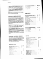
Tableof contents
TABLEOF
Specifications
MC 1210
CONTENTS
page
GENERALINFORMATION
ANDINSTALLATION
Introduction
- ModularCuber
Unpacking
andInspection
Unpacking
andInspectionStorageBin
Location
andlevelling
installation
Stacking
: Mixedunitsinstallation
: Electronic
unitsinstallation
Electrical
connections
Watersupplyanddrainconnections
Finalchecklist
practice
Installation
a
e
4
4
4
5
5
7
8
8
8
9
OPERATING
INSTRUCTIONS
Startup
Operational
checks
10
11
(Howit works)
OPERATING
PRINCIPLES
Freezing
cycle
Defrostor Harvestcycle
- Controlsequence
Operation
- Electrical
Operation
sequence
Component
description
15
17
18
18
19
ADJUSTMENT,
REMOVAL
ANDREPLACEMENT
PROCEDURES
Adjustment
of thecubesize
Replacement
of evaporator
temperature
sensor
Replacement
of condenser
temperature
sensor
Replacement
of ambienttemperature
sensor
Replacement
of icelevellightcontrol
Replacement
of P.C.Board
Replacement
of thewaterpump
Replacement
of waterinletsolenoid
valve
Removalof theflowcontrol
Replacement
of hotgasvalvecoil
Replacement
of waterdrainsolenoid
valve
Replacement
of waterdrainelectronic
timer
Replacement
of fan motor
Replacement
of spraybar
Replacement
of drier
Replacement
of hotgasvalvebody
platen
Replacement
of evaporator
Replacement
of aircooledcondenser
Replacement
of watercooledcondenser
Replacement
of waterregulating
valve(watercooledmodels)
Replacement
of compressor
Wiringdiagram
Servicediagnosis
23
24
24
24
24
24
25
25
25
25
25
25
26
26
26
26
26
26
27
27
27
28
29
MAINTENANCE
ANDCLEANING
INSTRUCTIONS
General
lcemaker
instructions
Cleaning
of watersystem
31
31
32
I
I
l
:I
l
:l
Page 2
t
SPECIFICATIONS
ELECTRONICCUBERMODEL MC 1210
requirements:
operating
lmpodant
MAX
MIN
10"c(50"F) 40'c(100'F)
Airtemperature
5"C(40"F) 40"C(100"F)
temperature
Water
1 bar(14psi) 5 bars(70Psi)
Waterpressure
variations
voltage
Electr.
rating
fromvoltage
+6%
onnameplate -'10%
specified
u
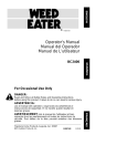
ice makingcapacity
WATERCOOLEDMOT}ELS
AIR COOLED MODELS
@
E
I
10
U)
600
[!
S
550
kÍ
tt
ul
fr
ft
5oo
I(r
450
^u
4oo
o
=
6so
uJ
N
N
(r
ul
u
Kg.
700
t
Kg.
650
t,lJ
(!
3
2
U
F
z
U
À
3
8
u
o
F
600
t
uJ
5
w
ul
l
ó
o
E
F
s00
z
U
6
=
400
3
8
3
2
2
7
2
1
1
5
l
0
TEMPERATURE
WATER
5
38
32
27
21
15
l0
WATERTEMPERATURE
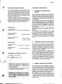
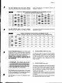
NOTE.Thedaityice-makingcapacityis directlyrelatedto thecondenserair inlettemperature,water
and age of the machine.
temperature
Tokeep vour SCOTSMANMODIILARCLIBERat peakperformancelevels,periodicmaintenanee
checkéhust be carried-outas indicatedon page37 of thismanual.
Productionchartsshownare indicatingtheproductionof MCMand MCLmodels.ForMCSmadels
ice productionis approx. 10/olower.
t-,
Page 3
o
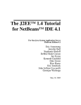
SPECIFICATIONS
l*i|=
tl
.
a
a
32r"615
lAIER Ilt Ft
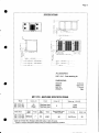
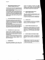
ACCESSORIES:
KSC1210- Cubestacking
kit
DIMENSIONS:
a
HEIGHT
WIDTH
DEPTH
WEIGHT
8 1 0m m .
1677 mm.
775 mm.
Kgs.
MC 1.210.MACHINESPECIFICAT]ONS
Model
Cond.unit
Finish
Comp.HP
Air
Water
Stainless
steel
Stainless
steel
5
M C 1 2 î 0A S
M C 1 2 1 0W S
Basic electr.
o
Basic
electr.
Amps
M C 1 2 1 0A S
380/50/3+N7
M C1 2 1 0W S
Water reo. - lV24 HR
1300
10200
Start
amps.
Watts
ElectricDowercons.
Kwh x 24 HR
N. of wires
Amps.fuse
52
4000
80
5x2.5mm
20
Cubesperharvest:
MCL288large- MCM408medium- MCS792small.
' Subiectto variation
accordingto ditlerentwaterandambienttemperature
conditions.
Page 4
ANDINSTALLATION
GENERALINFORMATION
A.
INTRODUCTION
andthe
thespecifications
Thismanualprovides
procedu
startresfortheinstallation,
step-by-step
for
maintenance
andcleaning
upandoperation,
CUBERMC1210.
MODULAR
theSCOTSMAN
ModularCubersof theMC 1210
TheElectronic
and
seriesare qualitydesigned,engineered
manufactured.
tested
Theiricemakingsystemsarethoroughly
providing
to fit theneeds
theutmostin flexibility
user.
of a particular
listings:
forthefollowing
Thisproductqualifies
a@@
to our
havebeenengineered
Theseicemakers
standards.
own rigid safetyand performence
TheVDE- SEV- WRCsealssignifythattheyare
listedwiththemandthattheycomplywiththe
of them.
standard
materials
and manufacturing
Thesesealsalso signifythat theseicemaker
andtestedby VDE
modelshavebeeninspected
- SEV- WRCinspectors
whoreserve
therightto
at
icemakers
periodically
examineproduction
compliance.
thefactoryto assurecontinued
NOTE.Toretainthesafetyandpertormance
built into this icemaker,it is importantthat
installationand maintenancebe conducted
in the manneroutlinedin thismanual.
StorageBin
SincetheMC 1210ModularCuberdo nothave
theirownattachedicestoragebin,it is necessary
to usethe Bin B 120.
b,/
stripsecuring
theplastic
3. a)Cutandremove
the cartonboxto the skid.
the
b) Removethe packingnailssecuring
cartonboxto the skid.
thetopofthecartonandremove
c)Cutopen
sheet.
the polystyreprotection
d) Pull out the polystyrepostsfrom the
cornersandthenremovethecarton.
4. Removetopandallsidepanelsof theunit
and inspectfor any concealeddamage.Notify
as
yourclaim
fortheconcealed
damage
carrierof
statedin step2 above.
5. Removeall internalsupportpackingand
maskingtapeandthe hardwarepackage.
lines do not rub
6. Checkthat refrigerant
andthat
ortouchotherlinesor surfaces,
against
thefanblademovesfreely.
u
_
fitssnuglyonto
7. Checkthatthecompressor
pads.
all itsmounting
B. Seedataplateon the rearsideof the unit
and checkthat localmainvoltagecorresponds
on it.
withthevoltagespecified
CAUTION.lncorrectvoltagesuppliedto the
icemakerwill void your parts replacement
program.
registration
9. Removethe manufacturer's
cardfromtheinsideof theUserManualandfillModelandSerialNumber
in all partsincluding:
takenfromthedataplate.
F o r w a r d t h e c o m p l e t e ds e l f- a d d r e s s e d
cardto Frimonîfactory.
registration
\,,
StorageBin-B120
1. Followthesteps1,2 and3aboveîo unpack
thestoragebin.
B.
ANDINSPECTION
UNPACKING
layit downon itsrearsideandfit
2. Carefully
thefourlegsintotheirsockets.
ModularCuber
3. Removeall internalsupportpackingand
maskingtape as well as the plasticice cube
1. CallyourauthorizedSCOTSMANDistributor
deflector.
or Dealerfor properinstallation.
of thepacking
inspecttheexterior
2. Visually
and skid.Any severedamagenotedshouldbe
carrieranda concealed
tothedelivering
reported
of
claimformfilledinsubjettoinspection
damage
the contentswith the carrier'srepresentative
present.
registration
4. Removethe manufacturer's
cardfromtheinsideof theUserManualandfillModelandSerialNumber
in all partsincluding:
takenfromthedataPlate.
F o r w a r d t h e c o m p l e t e ds e l f- a d d r e s s e d
cardto Frimontfactory.
registration
\.-
!
Page5
a
C.
LOCATION
ANDLEVELLING
ThislceCuberis designedfor
WARNING.
indoorinstallationonly.Extendedperiods
of operation at temperatureexceeding
the following limitationswill constitute
misuseunderthetermsof theSCOTSMAN
Manufacturer's
LimitedWarrantyresulting
in LOSSof warrantycoverage.
permanent
1. Position
theBinintheselected
location.
for selection
include:
Criteria
of location
a) Minimum
roomtemperature
10"C(50'F)
roomtemperature
40"C(100'F).
andmaximum
minimum
b) Waterinlettemperatures:
5oC
(40"F)and
maximum
40'C(100"F).
locationfor air cooled
c) Well ventilated
models.Cleanthe air cooledcondenser
at
frequent
intervals.
d)Service
access:adequate
spacemustbe
leftforallservice
connections
through
therearof
of 15 cm
the ice maker.A minimumclearance
(6")mustbeleftatthesidesoftheunitforrouting
coolingairdrawnintoandexhausted
outof the
compartment
to maintainpropercondensing
ooeration
of aircooledmodels.
2. LeveltheStorageBinAssyin boththeleft
to rightandfrontto reardirections
by meansof
legs.
theadjustable
gasket
Storage
Bintopmounting
3. Inspectthe
whichshouldbeflatwithnowrinkles,
to provide
a good sealingwhen the ModularCuberis
installed
on topof it.
\
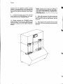
10. Installthe
twoplasticicecubedeflectors
by
hookingthem on the flangeof the ice chute
in unitbase(seeillustration).
openings
D. STACKINGINSTALLATION
A StackingKit KSC 1210is availableas an
of
accessory
on requestto allowthe installation
Cubersoneon topof theother.
two Modular
TheStacking
Kitis consisting
of:
a ) t w o p l a s t i c r e i n f o r c e dl c e C h u t e
Connections
P.C.Board
b) an Interface
c) an Extension
Cable
enablingto cover any stackinginstallation
combination
as:
Modular
a) Whenstackingan Electronic
type (Earlier
Cuberon an Electromechanical
series).
Modular
b) Whenstackingtwo Electronic
Cubers.
Mixedunits installation
1. Unloosethe screwsand removethe top
panels.
4. PlacetheModular
Cuberontopof Storage
binusingcarenotto wrinkleor tearthegasket.
2. Trace and removefrom the top of the
metalbracket
evaporator
of Electronic
Cuberthe
to be usedto securethe ice levelcontrolassv
insidethestoragebin
Cuberfrontsidein
5. Lifta littlebittheModular
orderto be ableto mount,in oneof thetwoice
chuteopenings,
theicelevelcontrolbracket.
Cuberfront
sidein
3. Lifta littlebittheModular
orderto be ableto mountthe ice levelcontrol
bracket.
6. Removethe PVCplasticplugclosingthe
roundholelocated
besidetheicechuteopening.
Modular
Cuberontopof
4. PuttheElectronic
unit.
the Electromechanical
for
7. Tracetheicelevelcontrolassy,
secured
ontothetopoftheevavorator
ofthe
thetransport
ModularCuber,anddirectit downthroughthe
roundholeintotheStorageBin.
unplugged
theicechutesfromboththeunits
5. Remove
of
andinsert,
through
theicedischarge
openings
lce Chute
the upperunit,the plasticreinforced
Connections.
Securethe ice levelcontrolassy on its
L
bracketby meansof thetwoscrewsfoundin the
package
withthe unit.
hardware
supplied
9. Makea cut (shear)in thePVCplasticplug
thatgoesfromitsedgeto thecenter;insertthe
icelevelcontrolcablein thecenterof theplastic
plugso to preventit fromanysortof contactwith
theunitframe,thenplaceagainthePVCplugin
the roundhole keepingthe cableexceeding
insidetheunit.
oortion
the ice levelcontrolterminal
6. Disconnect
plugfromtheP.C.BOARDof Electronic
Modular
Cuber.
7. Installandsecuretheicelevelcontrolassy
onitsbracketbymeansofthetwoscrewssupplied
withtheunit.
8. Directtheicelevelcontrolcablefirstto pass
opening
of thebottom
through
theicedischarge
Page 6
machinewith the protectivesheathcorrectly
locatedin correspondance
of thisopeningand
into
thento passthrough
theroundholeprovided
Modular
thebaseoftheElectronic
Cuber(Upper
unit).
9. Connectthe electricplugof the ice level
controlcable
to theCableExtension,
thenplugin thisoneintoits P.C.BOARDsocket.
10. Rotateclockwisethe TRIMMERsetting
screwlocatedin thefrontof P.C.BOARD,to its
power,so to compensate
maximum
thegreater
resistencecausedby the Cable Extension
addition.
NOTE. Replace the existing ice deflector/
withthenewlonger
bulbholdercombination
one,part number66049801, to preventthe
light beam of the lce Level Controlfrom
inErterringwith it.
e
11. Stick,withaccuracy,
therubberstripeonto
the upperedgeof thefrontpanelsof the lower
unitin orderto fill the air gap betweenthe two
machines.
12. Placeagainin theirposition
theicechutes
andfinallyre{italltheservicepanelspreviously
removed.
C
G
\-
PageT
Electronicunits installation
1. Unloosethe screwsand removethe top
panels.
2. Putthe secondElectronic
ModularCuber
ontothebottomoneandalignethetwocabinets
correctly.
3. Removetheicechutesfromboththeunits
andinsert,
through
theicedischarge
openings
of
the upperunit,the plasticreinforced
lce Chute
Connections.
4. Disconnect
the ice levelcontrolterminal
plugfromtheP.C.Boardof theupperElectronic
ModularCuber(nowcolledunit 2).
L
Connectthe secondaryOUTLETplug
(longerwire)of the Interface
P.C.Board
to the
P.C.Boardsocketof theunit 2 (seedrawing).
9. Turn clockwise(to its max. power)the
TRIMMERsettingscrew(locatedon the front
centerof P.C.Board)oftheicelevelcontrol
ofthe
unit2.
10. The Interface
P.C.Boardis nowready
to
-two
stop simultaneously
the operationof the
unitswhenthe infraredbeamof the ice level
controlis interrumped
by thestoredicecubes.
ATTENTION.After removal of the ice
cubes to re-establishthe infraredbeam
5. Securethe InterfaceP.C. Boardto the
bothunitsresumetheiroperationstarting
contactormetalbracketof the lowerunit (now
from the beginningof freezingcycle.
calledunit 1) by meansof the suppliedplastic
clamp.
Duringthe first freezingcycleit couldbe
possiblethat the ice cubes producedby
6. Disconnect
the ice levelcontrolterminal
one of the two ice makersbe not of the
plugfromtheP.C.Boardoftheunit1 andconnect
correctshape(cloudyand shallow)due
ittotheINLETsocketofthelnterface
P.C.Board
to
an insufficientwater level in its sump
(shorter
wire).
tank.This minorproblemwilldesappear
7. ConnecttheprimaryOUTLETterminalplugin the next batchbecausein the coming
harvest cycle the sump tank will be
of the InterfaceP.C. Board(wireof medium
properlyfilled-up.
lenght)to the P.C.Board
socketof theunit 1.
I
Page8
:
:l
therubberstripeonto
11. Stick,withaccuracy,
the upperedgeof thefrontpanelsof the lower
unitin orderto fill the air gap betweenthe two
machines.
lf water containsa high levelof impurities,it is
advisable to consider the installationof an
appropriatewaterfilteror conditioner.
theicechutes
12. Placeagainin theirposition
and finallyre-fitthe servicepanelspreviously
removed.
Watersupply- Watercooledmodels
D. ELECTRICALCONNECTIONS
to
See data plate for currentrequirements
determinewire size to be used for electrical
require
icemakers
AllSCOTSMAN
connections.
a solidearthwire.
from
aresupplied
icemachines
AllSCOTSMAN
pre-wired
only
andrequire
completely
thefactory
powerconnections
to the wire cord
electrical
at rearof theunit.
orovided
to its
Makesurethattheicemachineisconnected
fused(seedataplate
owncircuitandindividually
forfusesize).
variation
should
Themaximum
allowablevoltage
not exceed-10%and + 6/" ol the data plate
rating.Lowvoltagecancausefaultyfunctioning
for seriousdamageto
and maybe responsible
switchandmotorwindings.
theoverload
NOTE.Allexternalwiringshouldconformto
national,state and local standardsand
regulations.
Checkvoltageon the lineand the ice maker's
the unit.
dataplatebeforeconnecting
I
lce
Thewatercooledversionsof SCOTSMAN
inletwatersupplies,
Makersrequiretwoseparate
one for the watersprayedfor makingthe ice
cubes and the other for the water cooled
condenser.
Connectthe 314"malefittingof the waterinlet,
usingflexibletubingor a 3/8"O.D.copperpipe,
plumbing
tothécoldwatersupplylinewithregular
fittinoand a shut-offvalve installedin an
acceésiblepositionbetweenthe watersupply
lineandtheunit.
Waterdrain
I
draintube is a plasticor
The recommended
tubewith18mm(3/4')l.D.whichrunsto
flexible
an opentrappedand venteddrain.Whenthe
drainis a longrun,allow3 cmpitchpermeter(1/
4" pitchperfoot).
isalsorequired
unitdrain
connection
Aventatthe
for propersumpdrainage.
Waterdrain- Watercooledmodels
Connectthe 3/4"malefittingof the condenser
tubingora
a secondflexible
waterdrain,utilizing
and
totheopentrapped
3/8"O.D.coppertubing,
venteddrain.
E. WATERSUPPLYANDDRAIN
CONNECTIONS
General
Whenchoosing
thewatersupplyfortheicecuber
shouldbe givento:
consideration
a) Lengthof run
b) Waterclarityandpurity
watersupplypressure
c) Adequate
singleingredient
Sincewateristhemostimportant
much
iceyoucannotemphasizetoo
inproducting
thethreeitemslistedabove.
Low water pressure,below 1 bar may cause
malfunction
of the icemakerunit.
willtendto
minerals
excessive
Watercontaining
producecloudycolouredice cubes,plusscale
build-up
on partsof thewatersystem.
Watersupply
water
Connectthe3/4"malefittingofthesolenoid
foodgradeflexible
inletvalve,usinganapproved
tubeora 3/8"O.D.copperpipe,to thecoldwater
supplylinewith regularplumbingfiltingand a
position
in an accessible
shui-offvalveinstalled
thewatersupplylineandtheunit.
between
NOTE.The watersupply and the waterdrain
must be installed to conform with the local
code. ln some cases a licensedplumber and/
or a plumbing permit is required.
F.
t
FINAL CHECK LIST
1. ls the unit in a room where ambient
temperaturesare within a minimum of 10'C
(50dF)even in wintermonths?
2. ls there at least a 15 cm (6") clearance
aroundthe unitfor properair circulation?
3. Are the storagebin and the unit in level?
(TMPORTANT)
4 . H a v e a l l t h e e l e c t r i c a la n d p l u m b i n g
beenmade,and is the watersupply
connections
shut-offvalveopen?
5. Has the voltage been tested and checked
againstthe data plate rating?
\
Page 9
a
6. Has the water supply pressurebeen
checkedto ensurea waterpressureof at least1
bar(14psi).
10. Hasthe owner/user
beengiventhe User
Manualand
beeninstructed
ontheimportance
of
periodic
maintenance
checks?
7. Checkallrefrigerant
linesandconduitlines
to guardagainstvibrations
andpossible
failure.
11. Has the Manufacturer's
registration
card
beenfilledin properly?
Checkforcorrectmodel
and serialnumberagainstthe serialplateand
mailthe registration
cardto thefactory.
Havetheboltsholding
L
thecompressordown
beencheckedto ensurethatthecompressor
is
pads?
snuglyfittedontothe mounting
9. Havethebinlinerandcabinetbeenwiped
clean?
H.
12. Hastheownerbeengiventhenameandthe
phonenumberof the authorized
SCOTSMAN
ServiceAgencyservinghim?
INSTALLATIONPRACTICE
' 1 . Hand
shut-off
valve
2 . Waterfilter
?
Watersupplyline
(flexible
hose)
4 . 3/4"malefitting
5 . Powerline
6 . Mainswitch
7 . Drainfitting
8 . Venteddrain
9 . Drainfitting
1 0 . Venteddrain
11. Opentrappedventeddrain
WARNING.
This icemakeris not designedfor outdoorinstallationand will not functionin
ambienttemperatures
below10"C(50'D or above40'C (100"F).
This icemakerwill malfunctionwith water temperatureébeloirv5'C (40'F) or above 40'C
(100.F).
--.---
:
-
Page10
{
INSTRUCTIONS
OPERATING
i
I
I
I
I
I
STARTUP
theicemakerand
installed
Afterhavinocorrectly
lectrical
c o m o l e t e dt h e p l u m b i n ga n d e"Start-up"
performthe following
conn'ections,
procedure.
theunitfrontpanelandlocatethe
A. Remove
controlbox.
B. Throughthe controlbox coverlocatethe
screwhead)of
to a fillister
grooved
treàdlsimitar
selector.
theelectronic
Program
turnthe
Withthe helpof a reqularscrewdriver
(The
position.
heailintheOPERATION
selector
bitmustfittheheadslotendto end,
screwdriver
thisto avoidto spoiltheselectorheadslot).
i
I
l
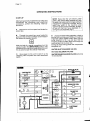
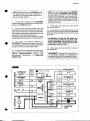
NOTE.Every time the unit returns under
power,
beenswitchedoff, both
'the after-having
waterinletvalveandthehotgasvalveget
energizedfor a periodof 5 minutes,thus to
admlt new water to the machine sumP
reseruoirtofillit up and,eventually,to wash
off any dirt that can have depositedin it
duringthe unitoff period(Fig.1).
I
i
I
:
D. Duringthe waterfillingoperation,checkto
throughthe
seethattheincomingwaterdribbles,
evaporatorplatendribblerholes,down into the
sump reservoirto fill it up and also that the
incoiningsurplusof waterflowsout throughthe
overflowpipe intothe drainline.
Duringtfte water fillingphase the components
energizedare:
I
WATER INLETSOLENOIDVALVES
HOT GAS SOLENOIDVALVES
powerto the unit to start.it up by
C. Give"Óru"
tne powerlinemaindisconnect
switching
switch.
WATER DRAINSOLENOIDVALVESfOTthEf iSt
15+20seconds.
@
ct)
CE
o
ct)
i
=
t!
ct)
|rl
CE
ELECTR.
TIMER
É,
uJ
o=
E
o
Él
=
Ét
CE
o
v)
ú)
Rx
Tx
'*=3
s =- o3
CE
CL
PUMP
WATER
lrl
CE
o-
=
C'
(J
ELECTR()NIC
CARD
--
Page'11
NOTE.lf in the 5 minutes length of the water
filling phase the machine sump reservoir
does not get filled with water up to the rim of
the overtlowpipe, it is advisable to check:
1. The water pressure of the water supply
line that must be at least 1 bar (14 psig)
Minimum (Max 5 ban70 psig).
2. The filtering device installed in the water
line that may reduce the water pressure
below the Minimum value of 1 bar (14 psig).
3. Any clogging situation in the water circuit
like the inlet water strainer and/or the flow
control.
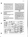
E. At completion
of the waterfillingphase
(5minutes)
theunitpassesautomatically
intothe
freezing
cyclewiththestartup of:
COMPRESSOR
WATERPUMPS
FANMOTOR(inair cooledversion)controlled
by the condensing
temperature
sensorlocated
withinthecondenser
fins(Fig.2).
OPERATIONAL
CHECKS
F. Install,
if necessary,
therefrigerant
service
gaugeson both the high side and low side
Schràder
valvesto checkthecompressor
head
andsuctionpressures.
NOTE.Onair cooledmodels,thecondenser
temperaturesensor,whichis locatedwithin
the condenser fins, keep the head
bondensino)pressurebetvveen15 and 16
bars (210-225psig). ln the water cooled
models the discharge pressure is kept
constantatthe valueóf t 6 bars225 psid bv
meansof the waterreoulatinoùatve'loóàted
on the watersupplvÌ'ne to íhe condenser.
ln caseofcondehèeTcloooino
suchtoprevent
theproperflowof thecoUinóairor.fànmotor
perature
out'of operation, the condeóser te'm
risesand whenit reaches7îC (17CF)the
condensertemperaturesensorshuts-offthe
icemakerwiththeconseauent
liaht-upof the
REDWARN//NG
LTGHT
iris.ql
The same happen even for the water cooled
versionwhere the condenserprobe is placed
in contact with the refriaerànt liouid line.
When its temperaturereaóhes 7f Ò (17e F)
it trips-off automaticallv the machine.
Afte:rhaving diagnosedihe reason of the rise
of temperature and removed its cause, it is
necessarv to turn the head of the selector alwavs úsino an appropriate scewdriver first ón the ÈE-SE/ iosítion then return it on
previous OPERATION position, thus to put
the machine in condition to initiate a new
freezing cycle. The same can also be done
by just switching OFF and ON the unit at
main line switch.
ln both cases the machine restarts with the
usualS minuteswaterfillingphase in orderto
provide enough water into the sump tank.
@
Uooóo
v)
E
o
u)
z,
ttl
ct)
|rI
G
=
ELECTR.
TIMER
k
E
lr,l
o=
É,
'xÍao
Él
=
Ét
E
o
é
Rx
Tx
+o
w =- o3
G
o-
FANMOTOR
WATER
PUMP
at)
ct)
E
CL
=
o
CJ
ELECTR()NIC
CARD
t
Page12
G. Check to see through the ice discharge
opening that the self propelledspray bar is
correctlyrotatingand that the water jets evenly
reachthe interiorof the invertedmoldcups,also
make sure that there is not excessive water
spillingout throughthe opening.
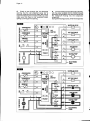
H. The icemakingprocesstakesplacethereby,
with the water sprayedinto the moldsthat gets
graduallyrefrigeratedby the heatexchangewith
the refrigerantflowing into the evaporator
serpentine.
Duringthef reezingprocess,whentheevaporator
ITE
lotWoo
u)E
or:
-
?lt 7
u - coND
=f,
- AMBIE
E
o-
Fru
= R x T x
At€
+Cr
H()TGASVALVE
ELECTR.
TIMER
CE
o
'*f8
w=E
É,
IL
É
WATER
PUMP
G'
an
(A
lrl
É,
È
=
o
ELECTRONIC
CARD
CJ
@
looóo
v)
E
o
u)
é
t
=
llJ
CA
tll
c0
E
ELECTR.
TIMER
É,
UI
o=
É,
o
'*=,8
rlt
z,
Rx
Tx
E rF:O +O
e =- ou
G
CL
CE
o
v)
rt)
trr
E
o=
c,
CJ
<_EhEcTR0Nrc
(
Page13
fallsbelowan established
value,
temperature
the evaporator
temperature
sensorsuppliesa
lowvoltagepowersignaltotheelectronic
control
in orderto activatean
device(P.C.BOARD)
electronic
timer.Thisonetakesoverthecontrol
ofthefreezing
cycleuptothecomplete
formation
of the icecubes(Fig.a).
NOTE.Thelength of the entirefreezingcycle
is governed by the evaporator temperature
sensor which has itsprobe placed in contact
with the evaporator serpentine (Non
adjustable) in combination with the electronic
timer (Adjustable) incorporated in the
P.C.BOARD.
The timer adjustment is factory set in
consideration of the cooling version and of
the ice cube size (Small, Medium, Large).
It is possible, however, to modify the timed
length of the freezing cycle, by changing the
DIP SWITCH keys setting.
In Tab\e B of PRINCIPLE OF OPERATION
are shown the varioustime extensionsof the
freezing cycle second phase, in relation with
the different DIP SWITCH keys settings.
f.
After about 17-20 minutes from the
beginningof the freezingcycle,in an hypothetic
ambienttemperatureof 21"C,the defrostcycle
takes placewith the hot gas and the water inlet
valvesbeingsimoultaneously
activated(Fig.5).
The electricalcomponents
in operationare:
COMPRESSOR
WATER PUMPS
WATER INLETSOLENOIDVALVES
HOT GAS VALVES
WATERDRAINSOLENOIDVALVESforthefirst
15-20 seconds.
NOTE. The length of the defrost cycle is
determinedby the DIP SWITCHkeys setting
in conjunctionwith the ambienttemperature
sensor located justin front of the condenser.
The length of defrost cycle can be adjusted
by changing the combinationsetting of keys
5,6 and 7 of DIP SWITCH as illustrated on
Table C of PRINCIPLE OF OPERATION.
As shown, per each individual keys
combination,it is possible to have a different
length of the defrost cycle in relation to the
different ambient temperature situations;
shorter when the ambient temperature is
high and longerin colderambientstopartially
compensatethe length of the freezingcycle,
whichis longerin high ambienttemperatures
and shorter in low ones.
J. Check,during the defrostcycle, that the
incomingwaterflowscorrectlyintosumpreservoir
in orderto refillit and that the surplusoverflows
throughthe overflowdraintube.
K. Checkthetextureof icecubesjustreleased.
They haveto be in the rightshapewith a small
depressionof about5-6 mm in theircrown.
lf not,waitfor thecompletionof thesecondcycle
beforeperformingany adjustment.
@
5ooóo
q)
É
o
u)
z
trr
(t)
trr
!c
- coN
E
. AMB
=
ltl
CL
c,
..x=a
tlr
=
Él
CE
o
?t)
ct)
|rI
CE
o=
o
(J
ELECTR.
TIMER
É,
=
Rx
#
C()NTACT()R
C()IL
te =
- c t3
CE
o-
FAN TOR
WATER
PUMP
Page14
lf required,
thelengthofthetimedfreezing
cycle
canbe modified
by changing
the DIPSWITCH
keys settingas illustrated
in OPERATING
PRINCIPLE.
lf the ice cubesare shallowand cloudy,it is
possible
thatthe ice makerrunsshortof water
duringthefreezing
cyclesecondphaseor, the
qualityof thesupplied
waterrequires
theuseof
an appropriate
waterfilteror conditioner
or the
installation
of the optional
waterdrainvalvekit
KWD.
L. To be sureof the correctoperationof ice
placeonehandbetween
levelcontroldevice,
its
sensing"eyes"to interrupt
thelightbeam.
The RED LIGHTlocatedin the front of the
goesimmediately
P.C.BOARD
OFF,and after
60seconds,
theunitstopswiththesimultaneous
glowingof the2nd YELLOWLIGHTto monitor
(Fig.6).
theBINFULLsituation
Take the handout from the ice levelcontrol
sensorsto allowthe resumption
of the light
beam;theREDLIGHT,located
inthefrontofthe
P.C.BOARD,
willglowimmediately.
Afterapproximately
6 secondsthe ice maker
resumeitsoperation
glowing
withtheimmediate
oftheFOURTHYELLOWLIGHTindicatinoUNIT
lN
OPERATION
and the extinouishino
of the
..BIN
FULL''YELLOWLIGHT.
NOTE. The ICE LEVEL CONTROL
(NFRARED SYSTEM)is independentfrom
the temperaturehowever, the reliabilityof its
detection can be affected by external light
radiations or by any sort of dirt and scale
sediment which may deposit directly on the
light source and on the receiver.
To prevent any possible ice maker
malfunction,due to negative affection of the
light detector, it is advisable to locate the unit
where it is not reached by any direct light
beamorlightradiation,also itisrecommended
to keep the bin door constantlyclosed and to
follow the instructions for the periodical
cleaning of the light sensor elements as
detailed in the MAINTENANCE AND
CLEANING PROCEDURES.
M. Removethe refrigerant
servicegaugesif
fittedandre-fittheunitsevicepanelspreviously
removed.
N. Instructthe owner/useron the general
operationof the ice machineand aboutthe
cleaning
andcareit requires.
@
oóooo
v)
É
cl
v)
=
l&l
rt)
trl
E
É
ul
o=
ELECTR.
TIMER
AMB
E
o
trl
z,
Ét
É,
o
v)
u)
ul
E
o-
=
o
CJ
a??
Rx
Tx
+G
oÈg
-o
CE
CL
WATER
PUMP
Page15
PRINCIPLE
OF OPERATION
How it works
W h e n t h e t e m p e r a t u r eo f t h e e v a p o r a t o r
serpentinedropsto a pre-setvalue,
theevaporator
sensor probe changesits electricalresistance
allowinga lowvoltagecurrent(B-10volts)to flow
to the P.C. BOARDwhich in turn activatesan
electronictimer.
The timer,which is builtin the P.C. BOARD,
takes over, from the evaporator temperature
sensor,the controlof the freezingcycleup to its
completion.
IntheSCOTSMAN
Modular
CuberMC1210the
waterusedto maketheiceis keptconstantly
in
circulation
by fourelectric
waterpumps(onefor
eachevaporator)which
primesit to thenozzles
of the selfpropeller
spraybar fromwhereit is
divertedinto the invertedmold cuos of the
(Fig.B).
evaporator
A smallquantityofthesprayedwaterfreezesinto
ice; the rest of it cascadesby gravityinto the
sumpassembly
belowfor recirculation.
FREEZING
CYCLE(Fig.A)
Thehotrefrigerant
gasdischarged
outfromthe
compressor
reaches
thecondenserwhere,
being
cooleddown,condenses
intoliquid.Flowing
into
the liquidlineit passesthroughthe drierfilter,
thenitgoesallthewaythrough
thecapillary
tube
where,due to the heatexchanging
action,it
loosessomeofitsheatcontentsothatitsoressure
andtemperature
areloweredas well.
Nextthe refrigerant
entersintothe evaporator
(whichhas a largerl.D. then the
serpentine
capillary)
and startsto boiloff;this reactionis
emphasizedby the heat transferredby the
sprayedwater.
The refrigerant
then increases
in volumeand
changesentirelyintovapor.
The refrigerant
vaporthenpassesthroughthe
(usedto preventthatany
suctionaccumulator
smallamountof liquidrefrigerant
mayreachthe
compressor)
andthrough
thesuction
line.Inboth
theaccumulatorandthe
lineitexchanges
suction
heatwiththerefrigerant
flowingintothecapillary
tube (warmer),beforeto be suckedin the
compressorand to be recirculated
as high
pressure,
hightemperature
gas.
Thefreezing
cycleiscontrolled
bytheevaporator
temperature
sensor(whichhasitsprobeincontact
withtheevaporator
serpentine)
thatdetermines
thelengthof thecyclefirstportion.
rr
ATTENTION.
In case, after 15 minutes
from the beginningof the freezingcycle,
thetemperature
of theevaporator
sensor
probeis higherthen0"C(32'F)(shortage
of refrigerant,inoperativehot gas valve,
e t c . ) t h e P . C . B O A R Ds w i t c h O F F
immediately the unit with the
simultaneuosblinkingof the WARNING
REDLED.
Thelengthof thissecondportionof thefreezing
cycleis pre-fixed
andrelated
to thesettingofthe
firstfour DIP SWITCHkeyswhichis madein
relation
withthedifferent
unitversions.
InTableB areindicated
thevarious
lengths
ofthe
secondportionof freezing
cycle(Timemode)in
relation
to thedifferent
combinations
of the DIP
SWITCHKEYS.
In TableA herebelow
are illustrated
the DIP
SWITCHkeyscombinations
forthedifferent
unit
versions
as theyareset in thefactory.
DIP SWITCHKEYS FACTORYSETTINGCOMBINATIONS
D|PSW|TCH
ON
M C L1 2 1 0
1
I
2
I
3
5
T
I
T
I
7
6
I
I
ON
OFF
4
T
OFF
M C M1 2 1 0
NOTE. Thechange of the electricpotentialof
the evaporator sensor with the consequent
activationof the timer (Timemode) is signalled
by the glowing-upof the RED LED located in
the front of the P.c. BoARD.
I
I
T
I
10
I
I
I
T
I
I
I
I
T
Page16
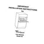
@
9IIHIIIUBE lfd'o'
tff
ill
rff
fll
@
$$uor
t#ro*
000
000
000
000
Page 17
The electrical
components
in operation
during
thefreezing
cycleare:
COMPRESSOR
FANMOTOR(inaircooledversion)
WATERPUMPS
CONTACTOR
COIL
andduringthe secondphaseof freezingcycle
(Timemode)theyarejoinedby the
ELECTRONIC
TIMER
The refrigerant
headpressure,
in thecourseof
the freezingcycle,rangesbetween15 and 16
psig)beingcontrolled
bars(210-225
bythetemperaturesensor probe locatedwithin the
condenser
fins(aircooledversion)
or, it is kept
constant
at 16 bars(225psig)by meansof the
waterregulating
valve(watercooledversion).
Ontheaircooledversion,
thecondenser
temperaturesensor,when sensesa risingof the
condensertemperature
beyondthe pre{ixed
limit,changesitselectrical
resistance
andsend
a lowvoltagepowerflowto the MicroProcessor
of P.C.BOARDwhichinturnenergizes,
through
a TRIAC,theFANMOTOR.
Whenthe oppositesituationoccures,i.e. the
getsbelowthepreJixed
condenser
temperature
limit,thetemperature
sensorchangesagainits
electrical
resistance
reducing
therefore
thecurrent
flowto the P.C.BOARDto causethefanmotor
to temporary
cut-off.
At the startof the freezingcyclethe refrigerant
suction
or lo-pressure
lowersrapidly
to 3,3bars- inrelation
gradually
45psigthenitdeclines
with
- to reach,atthe
thegrowing
of theicethickness
endof thecycle,approx.1 bar-l4 psig withthe
cubesfullyformedin thecupmolds.
Thetotallengthofthefreezing
cyclerangesfrom
20lo 25 minutes.
DEFROST
OR HARVEST
CYCLE(Fig.C)
As the electronic
timerhascarriedthe system
throughout
thesecondphaseof freezingcycle,
thedefrostcyclestarts.
ATTENTION.
In case the unit be able to
reach0"C(32"F)evaporatingtemperature
within 15 minutes,but after 45 minutes
fromthe beginningof thef reezingcycleit
has not yet reachedthe evaporatortemperatureof -15"C(5'F)the machinegoes
straightintothedefrostcycleomittingthe
timed portion of the freezingcycle relied
to the setting of the first four DIP
SWITCHES.
NOTE.Thelengthof thedefrostcycleis predetermined
bythesettingoftheDIPSWITCH
KEYSNO. 5, 6 and 7 and it is reliedas well
to the ambienttemperatureas detailedin
TableC.
NOTE.ln case the condensertemperature
probesen sesthat the condenser temperature
has rised to 7fC ft7eF) for one of the
followingabnormalreasons:
CLOGGED CONDENSER(Air cooled
version)
FAN MOTOR OUT OF OPERATION(Air
cooled version)
INSUFFICIENTFLOW OF COOLING
WATER(Watercooledversion)
AMB IENTTEMPERATURE HIGHER THEN
The electrical
in operation
components
during
thisphaseare:
COMPRESSOR
WATERPUMPS
WATERINLETSOLENOID
VALVES
HOTGASSOLENOID
VALVES
WATERDRAINSOLENOID
VALVESforthefirst
15-20 seconds.
it causesthetotalandimmediateSHUT-OFF
of the machinein order to preventthe unit
fromoperatingin abnormaland dangerous
conditions.
Whentheice makerstopson accountof this
protectivedevice,there is a simultaneous
glowingof theREDLED,warningtheuserof
the Hi Temperaturesituation.
After having eliminatedthe source of the
condenserhilemperature, to restart the
machineit is necessaryfirst,to rotatefor a
while the program selector on RE-SET
position then, to rotate it again on
position.
OPERATION
Thesamecanbe donebyjustswitchingOFF
and ON the unitat mainline switch.
Theicemachineresumesitsnormaloperation
by going throughthe 5 minuteswaterfilling
phase.
Theincoming
water,passingthroughthewater
inletvalveand the flowcontrol,runsoverthe
evaporatorplatenand then flows by gravity
throughthe dribblerholesdownintothe sump/
(Fig.D).
reservoir
Thewaterfillingthesump/reservoir
forcespartof
the surpluswaterfrom the previousfreezing
cycleto go outto thewastethroughtheoverflow
pipe.Thisoverflowlimitsthe levelof the sump
waterwhichwill be usedto producethe next
batchof icecubes.
Meanwhile,
thehighpressure,
hightemperature
refrigerant,
fromthecompressor,
discharged
flows
throughthe hot gas valve directlyinto the
evaporator
serpentine
by-passing
thecondenser.
Thehotgascirculating
intotheserpentine
of the
evaporator
warmsupthecoppermoldscausing
the defrostof the ice cubes.The ice cubes,
released
fromthe cups,dropby gravityontoa
slantedcube chute,then througha curtained
openingtheyfallintothestoragebin.
4ec 00eF)
Page18
';;t,';à;'iàry
NOTE.Thetengthof thedefrostcycl?,factgry,
ín a"cordancewnh tt19t
?9tu:lt
(asshownonTableC)'
à"mOilntiò,íperature
For instance,in high ambienttemperature
it canbe redugedtopcoyel s-o119
situation,
of thetimespentfor thelongertreezngcycte'
hot,gas
At theendof thedefrostcycle,both.the
machine
the
so
ólose,
valves
;iài-d;àt"iinlet
anotherfreezingcycle'
iÀitiates
Electronic Controls & Sensors """'
EvaporatorSensor
CondenserSensor
AmbientSensor
lce LevelControl
At the startof thefreezingcycle,the evaporator
resensorcontólsihelengthof thefirst
temperatu
a
òàri ót the freezingcycle' As it reacnes
low
a
it
slpplies
5ilà"ìàttii'eo-tèmp"erature,
to
i;Eé; il;iént io the P'c' BoARDin.order
over
takes
which,
timer
electronic
the
aótiuàte
-f
tne tieezing cvcle-fqr.a pre ixed
i#' ;.tòi;i
tòtneDlÈswlrcHkevssettins
iiri",àóóór.oins
(seeTab.B).
'ilréli,r"óiory
NOTE. The evaporator temp.eratu.re
is thesamefo.ratt.the
pre-ée1,
in thefietd'
adiustabte
,óiàéiiàra ís'not
cycle2rdphase
the freezing.
Oncecompleted
jnto
ìÉe-;y;óti gòès automaticailv the.defrost
à".rÀîr'ictràlsohasa pre-fixédlengththatcan
ng'upon the-actual ambient
rfiòiirv""Jiv oàÈenoi
c' - - -^,
showriinTable
ad
ieiìpeíatuie
cvcletheP'C'BOARD
Xi;ffiftìiln ottheoetrost
;;ffi'fid;]rré uni to startàgaina newrreezing
cycle.
. ELECTRICAL
SEQUENCE
OPERATION
The followingchartsillustratewhich-switches
areONor OFFduringa
ànOwnicncohponents
cycle' icemaking
the
of
óàrtiòrtàipnasb
reference'
a
for
diagram
wiring
tÉe
to
hétet
as
iiél"btoii tÈéwÍringóiagramshowstheunit
Cycle'
Freeze
Timed
it is in the
a
a
a
a
TIMED FREEZE
Electricalcomponents(Loads)"""
. CONTROL
SEQUENCE
OPERATION
ON OFF
Compressor
FanMotor(Aircooledonly)andTRIAC
HotGasValves
lnletWaterValves
Relay1 Coil"""""""""""
P.C.Board
2 & 3 Coil
RelaY
P.C.Board
WaterPumps
Coil'............'
Contactor
Timer...'.'...'.
Elecîronic
ElectronicControls& Sensors"""'
Sensor
EvaporaÎor
Sensor
Condenser
Sensor
Ambient
lce LevelControl
ON OFF
a
a
r
a
a
a
a
a
a
a
a
ON OFF
a
a
a
a
HARVEST
FREEZE
BEGINNING
ON OFF
Electricalcomponents(Loads)"""
a
Compressor
FanMotor(Aircooledonly)andTRIAC
a
HotGasValves
a
lnletWaterValves
a
RelaY1 & 2 Coil
P.C.Board
a
Relay3 Coil"""""""""""
P.C.Board
(Loads)"""
components
Electrical
ComPressor
WaterPumPs
Coil'....'.'...."
Contactor
Timer.'..'......
Electronic
Fan Motor(Aircooledonly)andTRIAC
ON OFF
'
'
ili:,î?:,::,):,ì";
Relay1 Coil"""""""""""
P.C.Board
P . C . B o aR
r de l a Y 2 & 3 C o i l
WaterPumPs
Coil......."""'
Contactor
Timer..........'
Electronic
:
'
'
ElectronicControls& Sensors"""'
Sensor
Evaporator
Sensor
Condenser
AmbientSensor
lce LevelControl
a
a
a
ON OFF
a
a
a
a
Page19
-*VI
I
Lr
OPERATING
CHARACTERISTICS
On air cooledmodelsduringthe freezingcycle
pressure
is keptbetween15 and
thedischarge
psig)bythecondenser
tempe16 bars(210+225
raturesensorandat the sametimethe suction
pressure
reaching
itslowest
willgradually
decline,
pointjust beforeharvest.Compressor
amps
a similardrop.
experience
On water cooled,the dischargepressureis
maintained
duringthefreezecycleby
constant,
valveat 16bars(225psig).
thewaterregulating
andcompressor
amps
However,
suctionpressure
freezesice.
willstilldeclineas themachine
Freeze Cycle
AverageDischarge
15-16 bars (210+225psig)
PressurefuC:
AverageDischarge
Pressure
WC:
16 bars (225 psig)
End
SuctionPressure
FreezeCycle:
1.5bar (21 psig)
DESCRIPTION
COMPONENTS
A.
EVAPORATORTEMPERATURE
SENSOR
sensorprobe,
The evaporatortemperature
ne,
serpenti
locatedincontactwiththeevaporator
temperadetectsthedroppingof theevaporator
tureduringthe freezingcycleandsignalsit by
flowtothemicroprocessor
of
supplying
a current
P.C.BOARD.
theevaporator
According
to thecurrentreceived,
powerto the P.C.BOARDfirst,
sensorsupplies
whenitreachs
0'G(32oF),
secondat-15"C(5'F);
inthissecondcaseitsupplypowertotheelectronic
timerbuiltintothe P.C.BOARDso thatit may
takecontrolof the lengthof the 2nd phaseof
freezing
cycle.
bythe
Thelengthof thetimedphaseis pre-fixed
settingof the keys 1, 2, 3 and 4 of the DIP
SWITCH.
timer (-15"C
The activationof the electronic
- 5'F) is monitored
up of theRED
by thelighting
LEDolacedin thefrontof the P.C.BOARD.
inthemidperiod
Thislighting
usually
upoccures
of the freezingcycleand signalsthe switching
fromthefirstto thesecondphaseof thefreezing
cycle.
,o.E:l o tl.rHarvest Cycle
B. CONDENSERTEMPERATURESENSOR
Average Discharge
7+14bars ('100-195psig)
Pressure:
resensorprobe,located
Thecondenser
temperatu
fins(aircooledversion)
or
withinthecondenser
version)
incontactwith
thetubecoil(watercooled
variations
temoerature
detectsthe condenser
current,at low
and signalsthemby supplying
voltage,
to the P.C.BOARD.
In the air cooledversions,in relationto the
of
currentreceived,
themicroprocessor
different
the
supplies,
through
aTRIAC,
theP.C.BOARD
powerat highvoltageto thefan motorso to cool
andto reduceitstemperature.
thecondenser
risesand
temperature
In casethe condenser
75'C (170"F)thecurrentarriving
to the
reaches
is suchto causean immediate
microprocessor
operation.
andtotalstopof themachine
AverageSuction
Pressure:
psig)
4+7bars(55+100
REFRIGERANTCHARGESUVA HP 81
Air & WaterCooledVersion
(70oz)
ir. trpooo srams
!
I
Íiv
NOTE.Beforechargingthe refrigerantsystem
always check the type of refrigerant and
quantity as specified on the individual ice
machinedataplate.
Therefrigerantchargesindicatedarerelated
to averageoperatingconditions.
As SUVAHP 81 iS A bIANdOf
WARNING.
differenttypesof refrigerantsit is imperative to chargethe systemonly in liquid
phasein orderto avoidto altertheir mixup percentage.
C. AMBIENTTEMPERATURESENSOR
Theprobeof thissensor,locatedin thefrontof
(Aircooledversion)
and
theicemakercondenser
(Water
onthewatersupplylineto thecondenser
cooledversion)has the functionto detectthe
and, by
ambientor the water temperature
resistance,
supplies
a
itsownelectrical
changing
currentflowto the P.C.BOARD.
different
This differentcurrentflow receivedby the
iselaborated
bythemicroprocessor
P.C.BOARD,
in orderto extendor shortenthe defrostcycle
shofier
situations,
length(longerincoldambient
in warmones).
Page 20
D. ICEBINLEVELLIGHTCONTROL
Theelectronic
icebinlevelcontrol,locatedinto
the storagebin, has the functionto stop the
operation
oftheicemachine
whenthelightbeam
betweenthe light sourceand the sensoris
interrupted
by theicecubesstoredintothebin.
Whenthelightbeamis interrupted
theREDLED
locatedinthefrontof theP.c. BoARDgoesoff;
in casethe lightbeamis constantly
interrupted
formorethan60seconds,
theicemachine
stops
withtheglowing-up
of the2ndYELLow LEDto
monitorthesituation
of icebinfull.
The 60 secondsof delaypreventthat an ice
scoopmovement
ortheicedropping
through
the
icechute(interrupting
fora whilethelightbeam)
canstoptheoperation
of theunit.
As soon as the ice is scoopedout (withthe
resumption
of the lightbeambetweenthe two
infrared
sensorof icelevelcontrol)
theREDLED
is lighted
upandafter6 seconds
theicemachine
restarts
againwiththe extinguishing
of the2nd
YELLOWLED.
E.
P.C.BOARD(Dataprocessor)
TheP.C.BOARD,fittedin itsplasticboxlocated
inthefrontof theunit,consists
of twoseparated
printedcircuitsoneat highandtheotherat low
voltageintegratedwith a programselector,of
five alignedLEDSmonitoring
the operation
of
themachine,
oftwoextramonitoring
REDLEDS,
of one DIP SWITCHwith ten keys,of input
terminals
fortheleadsof thesensorprobesand
inputandoutputterminals
fortheleadsoftheice
makerelectrical
wires.
TheP.C.BOARDis thebrainof thesystemand
it elaborates,
throughits microprocessor,
the
signalsreceived
fromthefoursensors
inorderto
controlthe operationof the differentelectrical
componentsof
theicemaker(compressor,
water
pump,solenoid
valves,etc.).
By turningtheprogramselector
it is possible
to
putthe unitin thefollowing
different
situations:
CLEANING/RINSING.
The waterpumpis the
only electricalcomponentin operationand it
mustbe usedduringthecleaning
or the rinsing
procedure
of thewatersystemof icemachine.
STANDBY. The unit remainunderelectrical
powerbutOUTofoperation.
ltcanbeusedbythe
serviceengineer
in orderto stoptheunitduring
theserviceandinspection
operations.
lN OPERATION.
Theunitis running
through
the
freezing
anddefrostcyclesstopping
automatically
onlyat fullbinsituation.
RE-SET/HITEMPERATURE.
To be selected
to
resumethe unitoperation
whenthe ice maker
shutsoffdueto theintervention
of thecondenser
temperature
sensor(toohighcondensing
tempe-.
rature).
ThefiveLEDS,placedin a rowin thefrontof the
P.C.BOARD,monitorthefollowing
situations:
GREENLIGHT
Unitunderelectrical
power
YELLOWLIGHT
Unitshut-offat full
storagebin
REDLIGHT
Unitshut-off
dueto hi
condensing
temperatu
re
*il'
blinking
Unitshut-off
dueto too
hi evaporating
temperature
YELLOWLIGHT
Unitin freezing
operation
YELLOWLIGHT
Unitin cleaning/rinsing
mode
F.
DIPSWITCH
The P.C.BOARD
which controlsthe entire
operationof the ice maker,hasa DIPSWITCH
with ten switching keys whichallowto set up
programinordertoextendor
themicroprocessor
to shortenthe lengthof freezingand defrost
cyclesin relationto the differentmodelsand
versions
of icemachines.
-l
Page 21
cycle (controlledby the electronictimer) as
detailedin table B.
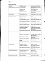
The DIP SWITCHfirst four keys setting
determines
thelength
ofthe2ndphaseoffreezing
I@
LENGHTOF TIMEDPORTIONOF FREEZINGCYCLEACCORDINGLYTO THE
DIP SWITCHSETTINGCOMBINATIONS
1
2
3
4
2
3
4
I
I
I
v,'
r
f
I
,
v,,
r
2
v,t
-a
v,t
AC
I
'
I
I
I
I
I
I
I
E
-
A
7t
-
'
v,.
^
È
A
v'.
r
È
2? min
o
rlr
r:hiF
r
I
I
I
I
v.r
I
r
f
-eri^
13
min
The DIP SWITCHkeys 5, 6 and 7 setting
determines
the lengthof the defrostcycle
vilr..
--:
r
/mrn.
r
r
Smin.
r
r
r
3min.
r
r
r
1inin.
O F F T -
1 2 # r
<6
r
r
I
I
r
r
1 1 O N OFF
lQmi^
I
I
c"F
I
-
I
f
q
I
r
I
t6óió
I
#
T
r
to theambient
according
temperature
sensoras
specified
in tableC.
LENGHTOF DEFROSTCYCLE(tN SEC.)ACCORDTNG
TO THE
AMBIENTTEMPERATUREAND TO THE DIP SWITCHSETTINGCOMBINATIONS
7 | 0+5'C 5+10"C 10+15"C 15+20'C 2O+25"C25+30'C 30+35"C 3b+40"C
ON
OFF
180'
150'
120'
of{
OFF
150'
120'
120'
120'
90'
90.
ON
OFF
180'
150'
150'
120'
120'
90.
ON
OFF
180'
150'
150"
120'
120'
120'
210
180'
180"
150"
150.
150.
The8th DIPSWITCHkeyallowsto makea rapid
checkupoftheP.C.BOARDoutputconnections
(compressor,
waterpump,fanmotor,waterinlet
andhotgassolenoid
valves)energizing
themin
(2 seconds)
rapidsequence
oneby one.
DURINGTHE AUTOMATIC
OPERATION
OF
THE ICE MAKERTHIS KEY MUSTBE SET IN
OFFPOSITION.
A T T E N T I O NT. h e c h e c k u p o f t h e
P.C.BOARD
outputmustbe peÉormedin
a veryshorttimeinordertoavoidfrequent
start and stop (everyfew seconds)of the
electricalcomponentswhichmaydamage
them,especiallythe compressor.
o
The 9th key allowsthe operationof the water
pumpevenduringthedefrostcycle,as required
intheunitequipped
by therotating
spraybar,to
accelerate
the releaseof the icecubes.
The 1Othkey is notusedontheModular
Cuber
M C1 2 1 0 .
G. WATERSPRAYBAR(4 per unit)
On ModularCuberthespraybaris selfrotating
beingpropelled
by a streamof waterpassing
throughan holelocatedin onearmof thespray
bar and,throughits four nozzles,
the pumped
wateris sprayedin each individual
cup to be
frozenintoice.
H. WATERPUMP(4 per unit)
Thewaterpumpoperates
continually
throughout
thefreezing
anddefrostcycleto primethewater
fromthe sumpto the selfpropelling
spraybar
it spraysit
and,throughthefourspraynozzles,
into the invertedcup moldsto be frozeninto
crystalclearicecubes.
Thewaterpumpremains
inoperation
evenduring
thedefrostcycleinorderto helptherelease
ofthe
icecubes.
It isrecommended
thatthepumpmotorbearings
be checkedat leasteverysixmonths.
Page 22
I.
WATERINLETSOLENOID
VALVE.
3/4 MALEFITTING(2 per unit)
Thewaterinletsolenoid
valveisactivated
bythe
microprocessor
of the P.C.BOARDdurinfthe
first5 ininutes
of waterfillingphaseandas-well
duringthedefrostcycle.
Whenenergized
it allowsa meteredamountof
incoming
watertoflowovertheevaporator
cavity
to assistthehotgasindefrosting
theicecubes.
The waterrunningover the evaporatorcavity
dropsbygravity,
through
thedribbier
holesofthe
platen,intothe sumpreservoir
whereit will be
suckedby the waterpumpand primedto the
spraysystem.
J.
FANMOTOR(Air cooledversion)
The fan motoris controlled
throughthe P.C.
BOARDandtheTRIACby thecondenser
temperature
sensor.
Normally
itoperates
onlyduring
thefreezing
cycletodrawcooling
airthrough
the
fins.
condenser
In thesecondpartof thefreezing
cycle,thefan
motorcanrunat intermittance
asthecondenser
pressure must be kept between two
corresponding
head pressurevalues(15+16
psig).
bars-210+-225
L.
M. WATERREGULATING
VALVE
(Watercooledversion)
This valvecontrolsthe headpressurein the
refrigerant
systembyregulating
theflowofwater
goingto thecondenser.
As pressure
increases,
thewaterregulating
valve opensto increasethe flowof coolingwater.
HOTGASSOLENOID
VALVE(2perunit)
Thehotgassolenoid
valveconsists
basically
in
two parts:thevalvebodyandthe valvecoil.
Locatedon
thehotgasline,thisvalve
isenergized
throughthe microprocessor
of P.C. BOARD
duringthe defrostcycleandas wellduringthe
waterfillingphase.
Duringthedefrostcyclethehotgasvalvecoilis
activated
so to attractthehotgasvalvepistonin
orderto givewayto thehotgasdischarged
from
thecompressor
toflowdirectly
intotheevaporator
serpentine
to defrosttheformedicecubes.
K.
retrievethe refrigerantthroughoutthe ertie
system. lt compressesthe low pressure
refrigerant
vaporcausingitstemperature
to rise
and becomehighpressurehot vaporwhicfrb
thenreleased
throughthedischarge
valve.
COMPRESSOR
The hermeticcompressor
is the heartof the
refrigerant
systemandit is usedto circulate
and
N. CONTACTOR
Placedoutsideof thecontrolboxit is controlled
bytheP.C.BOARDinorderto closeor openthe
electrical
circuitto thecompressor.
O. WATERDRAINSOLENOID
VALVE
Energized
by a specialelectronic
timerduring
thefirst15-20seconds
of defrostcycle,itdiverts
tothedrain (fromthesumptank)alltheremaining
water-richof minerals-left
from the previous
freezing
cycle,whichispumped
outbythewater
pump.
P. WATERDRAINELECTRONIC
TIMER
Locatedbesidethe contactor,it energizesthe
waterdrainvalvefor thefirst15-20secondsof
the defrostcycleaccordingto the settingof its
knob.
NOTE.Adjust the knob of the waterdrain
electronictimer in order that all remaining
waterof previousfreezingcyclebe pumped
out fromthesumptank.
Page 23
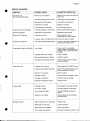
ADJUSTMENT,
REMOVAL
AND REPLACEMENT
PROCEDURES
)
A.
ADJUSTMENT
OFTHECUBESIZE
CAUTION.Before performing actual
adjustmentof the cubesize, checkother
possiblecausesfor cubesizeproblems,
referto the ServiceDiagnosisSectionfor
problemreviewand analysis.
Do not performany adjustmenttill the
icemakingsystem has progressed
through severalcompletefreeiing and
harvestcycles,to observesizeandquality
of ice cubesandwhetheror not the cubé
size problemexists.
SMALL
IDENTATION
o
l.
lf thecubesareshallow
size(lndentation
is
too deep)probablythe lengthof the second
phaseof the freezingcycleis too shortso, to
extendsuchlengthyouhaveto:
NORMAL SIZE-SHAPE
1. LocatetheDIPswlTcH on thefrontof the
P.C.Board.
2. Takenoteofthecombination
ofthefirstfour
DIPSWITCH
KEYSandcheckthe
corrisponding
lengthof freezing
cycle2ndphaseon TableB.
3. Changethe same DIP SWITCHKEYS
settingsothatitwillcorrespond
tothecombination
ontableB preceding
theoneremarked
atstep2.
Thiswillallowanextension
of thefreezing
cycle
of two moreminutes.
LITTLEOR NO
I C EI N C E N T E R
OF CUBES
SHALLOWSIZE
a
t
4. Observethe ice cubes in the next two
harvestsand eventuallyrepeatsteps2 and 3
aboveuntilproperice cubessizeis achieved.
Seefigure.
(lndentation
ll. lf thecubesareoversize
istoo
full)probably
the lengthof thesecondphaseof
thefreezing
cycleis toolong.
To shortensuchlengthyouhaveto:
1. LocatetheDIPswlTcH onthefrontof the
P.C.Board.
2. Takenoteofthecombination
ofthefirstfour
DIPSWITCH
KEYSandcheckthe
corrisponding
lengthof freezing
cycle2ndphaseon TableB.
3. Changethe same DIP SWITCHKEYS
settingsothatitwillcorrespond
tothecombination
on tableB comingnextto the one remarked
at
steo2.
Thiswillreducethefreezing
cyclelengthof two
mrnules.
*==:
THICKBULGE
SOLIDICE
OVER SIZE
4. Observethe ice cubesin the next two
harvestsand eventuallyrepeatsteps2 and 3
aboveuntilproperice cubessizeis achieved.
Seefigure.
Page 24
B.
REPLACEMENTOFEVAPORATOR
SENSOR
TEMPERATURE
REPLACEMENTOF ICE LEVEL
LIGHTCONTROL
E.
1. Removethe front centerupperpaneland
1. Removefrontcenterupperandlowerpanels
front left or right panel accordingto the location
andas wellthetopone.
of the ice levelcontrol.
fromthesuctionline
theinsulation
2. Remove
thesensorprobefromitsholder.
andwithdraw
plug
sensorterminal
3. Tracetheevaporator
on the rearsideof thecontrolboxand removeit
pulling
outtheterminal
fromitssocketbycarefully
plugsecuring
clip.
2. Trace the ice level light controlterminal
pluq(theonlyone withfourterminalpins)on the
'reai
diOeof tÉecontrolbox and removeit f rom its
socketby carefullypullingout the terminalplug
securingclip.
Removethe ice chutewhereis locatedthe
3.
ice level lightcontrolassy and removeit from its
4. Toinstallthereplacementevaporatorsensor
metal braóketby unloosingthe two securing
reverse.
followtheabovestepsin
screws.
C. REPLACEMENTOFCONDENSER
SENSOR
TEMPERATURE
1.
frontcenterupperandlowerpanels.
Remove
sensorprobelocated
2. Tracethecondenser
finson air cooledversion
withinthe condenser
andwithtrowit.
the
itbyopening
versionremove
Onwatercooled
plasticstrap(reusable)
theprobeto the
securing
liquidline.
refrigerant
sensorterminalplug
3. Tracethe condenser
on therearsideof thecontrolboxandremoveit
fromitssocketbycarefullypullingouttheterminal
plugsecuring
clip.
sensor
replacement
condenser
4. Toinstallthe
followtheabovestepsin reverse.
OF AMBIENT
D. REPLACEMENT
SENSOR
TEMPERATURE
4. Remove the PVC plastic plug from unit
base then withdrawthe entire ice level light
controlcableand terminalplugthroughthe hole
in the unitbase.
5. To installthe replacementice level light
controlfollowthe above steps in reverse.
NOTE. Slip in the ice level control cable in
the center of the plastic plug so to avoid any
sort of contact with the unit frame.
F.
OF P.C.BOARD
REPLACEMENT
1.
Removefrontcenterupperpanel.
plugs,located
2. Removeallsensorterminal
on the rear side of P.C. Board,by carefully
themoutfromtheirsocketsclips.
releasing
boardconnection
theterminal
3. Disconnect
oluofromthe rearsideof P.C.BOARDthen
Removefrontcenterupperandlowerpanels.
thesameto the
thefourscrewsholding
Lnlóose
it.
remove
plastic
box
and
control
sensorprobe,holdedon
2. Tracetheambient
fins-on
infrontofthecondenser
itsmetalbracket
P.C.BOARD
4. To installthe replacement
its
andremoveit byunloosing
aircooledversion,
reverse.
on
steps
above
follow
the
plasticclamp.
securing
On watércooledversion,removeit by opening
theprobeon
securing
strap(reusable)
theplastic
thewatersupplylineto thecondenser.
G. REPLACEMENTOFTHEWATERPUMP
plugon
3. Tracetheambientsensorterminal
therearsideofthecontrolboxandremoveitfrom
1. Removeleftor rightfrontpanels.
plug
itssocketbycarefullypullingouttheterminal
clip.
securing
2. Locatethe waterpump in the front left
chamber.
cornerof theevaPorator
ambientsensor
4. To installthe replacement
followtheabovestepsin reverse.
3. Removetheplasticicechuteandthrough
tracetheplastichose
opening
theicedischarge
fromtheportofthepumpbody.
disconnecfit
and
NOTE.Both the condenserand ambient
sensorsare equippedby the sameterminal
4. Unloosethe screwand the yellowgreen
oluo
andsocket.Toavoidconfusionon their
'insíattation
qroundwire.Tracethe pump electricalwire
it must be obseruedthat the
them.
leadsanddisconnect
condensersensor terminalplug and its
socketare of differentcolour
corresponding
ú
thepump
5. Removethetwoscrewssecuring
comparedto the otherones.
to sumptank.
1.
i
Page 25
6.
Pulloutthepumpassyfromsump.
7. To installthereplacement
pumpfollowthe
abovestepsin reverse.
H.
REPLACEMENT
OFWATERINLET
SOLENOID
VALVE
1. Closetheshut-offvalveonthewatersupply
lineanddisconnect
itfromthewaterinletfittingat
the rearof the modular
cuber.
4. Unloosethe screwssecuring
the valveto
the unitbaseand removeit.
5. To installthe replacement
water drain
solenoidvalvefollowtheabovesteosin reverse.
NOTE. When installing the new valve pay
attention to the water flow direction.
2 . R e m o v et h e r e a r c e n t e r p a n e l a n d
disconnect
theelectrical
leadsfromthesolenoid
valve.
L.
3. Unscrew
thetwoscrewssecuring
the inlet
solenoid
valveto thecabinet.
REPLACEMENTORTHEWATERDRAIN
ELECTRONICTIMER
1.
Removethe frontupperand lowerpanels.
4. Remove
thecorbinclamps
andplastic
hose;
thevalveis nowfree.
2. Unscrewthe terminalwires holdersof the
electronictimerand disconnectthe wires.
5. To installthe reDlacement
water inlet
solenoidvalvefollowtheiabovestepsin reverse.
3. Remove,by pullingout its holdingring,the
electronictimerfrom its bracket.
I.
TO REMOVE
THEFLOWCONTROL
4. To installthe replacementelectronictimer
followpreviousstepsin reverse.
1.
Removethe rearcenterpanel.
plastichoseconnecting
2. Locatethe
thewater
inletsolenoid
valvetothecopperwater
linegoing
to thetop of the evaporator
chamber.
3. Unloosethetwo
clamps
securing
thecopper
tubeaswellastheflowcontrolto theplastichose
andwithdraw
thecoppertube.
4. Bymeansofa4 MAscrewwithdrawthe
flow
controlassyfromtheinsideof plastichose.
o
3. Removethecorbinclampsandtheplastic
hosesfromthevalve.
J.
REPLACEMENTOFTHEHOT
GASVALVECOIL
1.
Remove
thefrontandthetopcenterpanel.
2. Removethehardware
securing
thehotgas
valvecoilto its body.
3. Tracetheelectricwires
belonging
to thehot
gasvalvecoilanddisconnect
them;thenliftthe
valvecoilfromthevalvebody.
NOTE.Adjust the electronictimer knob in
order that all remaingwaterfromprevious
freezingcyclebetotallypumpedoutfromthe
sumptank.
M. REPLACEMENTOFFANMOTOR
1.
Removethefrontupperandlowerpanels.
2. Unloose
thescrewssecuring
theaircooled
condenser
to the unitframeandopenit to gain
the accessto thefan motor.
3. Removescrewsandyellowgreenground
wire.Tracetheelectricalleadsof fan motorand
disconnect
them.
4. Removethe boltssecuringthe fan motor
protection
grid to the condenser
shroudthen
removethefan motorassembly.
4. Toinstall
thereplacement
hotgasvalvecoil
followpreviousstepsin reverse.
5. Withan appropriate
allenwrenchunsoolse
thescrewsecuring
thefanbladeto thefanmotor
shaftthenunloose
thenutsholding
thefanmotor
grid.
to itsprotecting
K.
REPLACEMENT
OF WATERDRAIN
VALVE
SOLENOID
6. To installthereplacement
fanmotorfollow
the abovestepsin reverse.
1.
Removethe rearpanel.
2. Traceand disconnectthe electricalleads
fromthewaterdrainsolenoid
valvecoil.
NOTE. When installinga new fan motor
checkthat the fan bladesdo not touchany
surtacesand movefreely.
I
Page26
N. REPLACEMENTOFSPRAYBAR
1. Remove
thefrontrightorleftsidepaneland
thentheplasticicechute.
2. Reachthrough
theiceopening
andfeelfor
the spraybar.
3. Rotatespraybar so that one of its end is
alignedwithiceopening.
4. Grabthespraybarcenterandliftitupoffthe
let bearinghub togetherwith its racewasher;
thendrawit outthroughtheiceopening.
spraybarfollow
5. To installthereplacement
abovestepsin reverse.
OF DRIER
O. REPLACEMENT
1. Removethe upperand lowercenterfront
panels.
2. On air cooledversion,ulloosethe screws
to unitframe.
securing
thecondenser
from the system
3. Recoverthe refrigerant
andtransferit in a bottleso to reclaimor recvcle
it.
linesfromthetwo
4. Unsolder
therefrigerant
endsof thedrier.
NOTE. Always install a replacement drier
whenever the sealed refrigerationsystem is
open. Do not replace the drier until all other
repairs or replacements have been
completed.
4. To installthe replacementhot gas valve
body follow the above steps in reverse.
NOTE.Thoroughlyevacuatethe systemto
after
removemoistureandnoncondensables
hotgas valvereplacement.
O. REPLACEMENTOFEVAPORATOR
PLATEN
1.
Removetopandrearpanels.
2. Removethe plasticcoverfromthe upper
platen.
partof the evaporator
3. Recoverthe refrigerantfrom the system
andtransferit in a bottleso to reclaimor recvcle
it.
tube
thecapillary
4. Unsolder
anddisconnect
neofevaporator
andhotgaslinefromoneserpenti
linefromthe other
and the suctiondischarge
serpentine.
drier remove
5. To installthe reolacement
factoryseals and solderthe refrigerantlines
to NOTOVERHEAT
thedrier
takingprecautions
body.
platenassemblyout of
5. Liftthe evaporator
its seat.
remove
6. Thoroughlyevacuatethesystemto
after drier
moistureand non condensable
replacement.
NOTE.Alwaysinstall a replacementdrier
systemis
wheneverthesealedrefrigeration
open.Do not replacethe drieruntilall other
repairs or replacementshave been
completed.
HP 81
7. Chargethe systemwithrefrigerant
andcheck
byweight(seedataplateof machine)
for leaks.
ATTENTION.
SUVAHP81 as it is a blend
of differenttypeof refrigerantsit hasto be
chargedonly in the liquidphase.
B.
Replacepanelspreviouslyremoved.
P.
HOTGASVALVE
REPLACEMENTOF
BODY
6. Toinstallthereplacementevaporatorfollow
the above steps in reverse.
NOTE.Thoroughlyevacuatethe systemto
removemoistureandnoncondensablesafter
nt.
evaporatorreplaceme
OF AIR COOLED
R. REPLACEMENT
CONDENSER
J to remove
1. Followthestepsin procedures
thehotgasvalvecoil.
1. Removefront centralupper and lower
oaners.
2. Recoverthe refrigerantfrom the system
andtransferit in a bottleso to reclaimor recycle
it.
2. Removefrom the condenserfins the
sensorprobeas wellas theambient
condenser
sensorprobe.
temperature
linesfromthe hot
the refrigerant
3. Unsolder
gasvalvebodyand removeit fromthe unit.
3 . R e m o v e t h e s c r e w s a t t a c h i n gt h e
to theunitframe.
condenser
:
. ì
u)
Page 27
4. Recoverthe refrigerant
from the system
andtransferit in a bottleso to reclaimor recycle
it.
the
3. Removecorbinclampanddisconnect
waterhosefromthe outletof waterregulating
valve.
linesfrom the
5. Unsolderthe refrigerant
condenser
andremoveit fromthe unit.
4 . U n l o o s et h e n u t s e c u r i n gt h e w a t e r
regulating
valveto theunitframe.
NOTE.Always installa replacementdrier
wheneverthesealedrefrigeration
systemis
open.Do not replacethe drieruntilall other
repairs or replacements have been
completed.
replacement
condenserfollow
6. Toinstallthe
the abovestepsin reverse.
NOTE.Thoroughlyevacuatethe systemto
removemoistureandnoncondensables
after
condenserreplacement.
S.
REPLACEMENTOFWATERCOOLED
CONDENSER
1. Removefront centralupperand lower
panels.
2. Removethe condenser
and the ambient
sensorprobesfromcondenser.
temperature
fromthe system
5. Recoverthe refrigerant
it in a bottleso to reclaim
andtransfer
or recvcle
it.
valvecapillary
6. Tracethewaterregulating
line
itsendfromtherefrigerant
tubeandunsolder
thenremoveit fromtheunit.
NOTE.Always installa replacementdrier
wheneverthesealedrefrigeration
systemis
open.Do not replacethedrieruntilall other
repairs or replacements have been
completed.
7. Toinstallthereplacementevaporatorfollow
the above steps in reverse.
NOTE.Thoroughlyevacuatethe systemto
removemoistureandnoncondensables
after
waterregulatingvalvereplacement.
NOTE. The water flow that passes through
the valve can be adjusted by means of the
valve setting stem.
3. Removeboltswhichsecurethecondenser
to theunitbase.
U. REPLACEMENTOFCOMPRESSOR
4. Remove
thecorbinclampsanddisconnect
condenser.
theplastichosesfromthewatercooled
1. Removethe frontcenterupperand lower
panelsas wellas therearone.
from the system
5. Recoverthe refrigerant
andtransferit in a bottleso to reclaimor recycle
ir.
2. Unloose
thescrewssecuring
theaircooled
to unit frameand open it to gain
condenser
compartment.
accessto thecompressor
linesfrom the
6. Unsolderthe refrigerant
condenser
andremoveit fromtheunit.
3. Removethe cover and disconnectthe
junction
electricalleadsfrom the compressor
DOX.
NOTE.Always install a replacementdrier
wheneverthesealedrefrigeration
systemis
open.Do not replacethe drieruntilallother
repairs or replacements have been
completed.
7 . To installthe replacement
condenserfollow
the above steps in reverse.
NOTE.Thoroughlyevacuatethe systemto
removemoistureandnoncondensables
after
condenser replacement.
T.
REPLACEMENT
OFWATERREGULATING
VALVE (WATERCOOLEDMODELS)
1.
Removethe rearcentralpanel.
valveonthewatersupply
2 ClosetheshuÈoff
it at therearof thecuber.
lineanddisconnect
fromthe system
4. Recoverthe refrigerant
andtransferit in a bottleso to reclaimor recvcle
it.
anddisconnect
boththe suction
5. Unsolder
linefromthecompressor.
lineandthedischarge
6. Removethefourcompressormountingbolts
fromtheunitbase.
andthecompressor
NOTE.Always install a replacementdrier
wheneverthesealedrefrigeration
systemis
open.Do not replacethe drieruntilallother
repairs or replacements have been
completed.
7. Toinstallthereplacementcompressorfollow
the above steps in reverse.
NOTE.Thoroughlyevacuatethe systemto
removemoistureandnoncondensables
after
compressorreplacement.
a
Page 28
WIRINGDIAGRAM
AIRANDWATERCOOLED
- 380/50/3+ N
220150-6013
KI
rt
&ì
sSr
{J
c/
g
B - WHITE
G - GREY
N - BLACK
A. BLUE
M - BROWN
GV - YELLOWGREEN
RINSING
FREEZER
OPER.
t
a
T O O H I G HT E M P E R A T U R E
a ffi
a lf
B I NF U L L
/7
POWERON
*
+;J
ru
P
RESETTOO HIGH
i
:
T E R M I N AB
L OARD
FREEZINGOPER.
STANDBY
BINSING
t
À
;
^
,
3
F
I
!
ó
F
E-
íU
<
u
J
F
i
+
8
8
È
r
F
L
=
U
,
É
V
.
9
r
E
é
,
l
ON MC-1210.N' 4WATER PUMP
è
5
í
U
ig
E
I
SENSORS
!)
<
(
U
>
L
^
z
)
À
z
)
U
@
o
o
F
z
u
PROTECTOR
l-
-J
* ON MC.12'10,
N.2 HOT GAS/WATERSOL. VATVES
CONNECTIONREPLACESNEUTRAL FOR MODEL 220150.60/3
\
Page 29
DIAGNOSIS
SERVICE
SYMPTOM
POSSIBLECAUSE
SUGGESTEDCORRECTION
Unitwill not run
(No warningLEDSglows)
Blownfuse in P.C.Board
Replacefuse & checkfor cause of
blownfuse
lncorrectcontactof fuse in P.C.B.
Check grip of the fuse holders
Main switchin OFF oosition
Turn switchto ON oosition
Inoperative
P.C.Board
ReplaceP.C.Board
Looseelectricalconnections
Checkwiring/Connector
(GreenLED-Power
ONglows)
P.C.Boardselectorin STANDBY
Move to OPERATINGposition
(BinfullLEDglows)
Inoperativeice levelcontrol
Reolaceice levelcontrol
(Red-alarm
LEDglows)
Highhead pressure
Dirtycondenser.Clean
Inoperativefan motor.Replace
Lo power cable in contactwith fram Check and repairor replace
(Red-alarmLED blinks)
Too high evaporatingtemperature
cyclesintermittently Low voltage
Compressor
Cubestoo small
, o
Cloudycubes
Shortageof water
Checkfor shortageof refrigerantor
for leakingof hot gas valve
Checkcircuitforoverloading
Checkvoltageat the supplyto the
lf low,contact
thepower
building.
company
withburntcontacts
Contactor
Cleanor replace
gasin system
Non-condensable
Purgethesystem
startingdevicewith
Compressor
Checkfor loosewiresin starting
loosewiresdevice
Freezing
cycletoo short
Reviewsettingof DIPSWITCHkeys
Capillary
tubepartiallyrestricted
Recoverrefrig.add new gas & drier,
after evacuatingthe system
Moisturein thesystem
Same as above
Shortage
of water
See remediesfor shortageof water
Shortage
of refrigerant
Checkfor leaks & recharge
sensor
Inoperative
evaporator
Replacesensor
of water
Shortage
forshortage
of water
Seeremedies
Dirtywater supply
Usewatersoftneror waterfilter
Accumulated
impurities
lce Machine
UseSCOTSMAN
cleaner
Spraybarnotrotating
Removespraybar& jet bearing
andcleanthem
Watersolenoidvalvenotopening
Replacevalve
Waterleakin sumparea
Locateand repair
Waterflowcontrolplugged
Removeand clean
Toolo waterinletoressure
mustbe 1 bar
Min.waterinletpressure
Page 30
DIAGNOSIS
SERVICE
SYMPTOM
POSSIBLE
CAUSE
lrregular
cubessize& somecloudy Some jets plugged
SUGGESTED
CORRECTION
Removespraybar& jet bearing
andcleanthem
Shortage of water
Seeshortageof water
Unitnot level
Levelas required
Spraybar not rotating
Removespraybar& jet bearing
and clean them
Cubes too large
Freezingcycle too long
Reviewsettingof DIPSWITCHkeys
Decreased
icecapacity
Inefficienîcompressor
Replace
Leakywater valve
Repairor replace
gas in system
Non-condensable
Recoverrefrig.add newgas & drier,
after evacuaiingthe sys-tem
Poorair circulation
Relocatethe unit or orovidefor
or excessive
hot location(Red-alarmLED glows) more ventilation
Poor harvest
Unit won't harvest
pressure
Incorrect
discharge
Overchargeof refrigerant
Correctthe charge.Purgeoff slowly
Capillarytube partiallyrestricted
Recoverrefrig.add new gas & drier,
after evacuatingthe system
Hot gas solenoidvalve leaking
Reolacevalve
Underchargeof refrigerant
charge to data plate indication
Spray bar not rotating
Removespray bar & jet bearing
and cleanthem
Dischargehead pressuretoo high
See incorrectdischargepressure
Too short defrosttime
Check& adjustDIPSWITCH
keys5-6-7
Restriction
in incomingwaterline
Checkwatervalvestrainerand flow
control.lf necessary
' enlargethe
flow controlorifice
Waterinletvalvenot opening
Valvecoilwith openwinding
Reolacevalve
Hot gas valve orificerestricted
Replacehot gas valve assy
Air vented holes in mold cuos
plugged
Cleanout holes
Dischargehead pressuretoo low
See incorrectdischargepressure
Inoperative
P.C.Board
ReplaceP.C.Board
Hot gas valve not opening
Valve coil with open winding
Replacevalve
Water solenoidvalve not opening
Valvecoilwith openwinding
Reolacevalve
Inooerativecondensersensor
Reolacesensor
InoperativeP.C.Board
ReplaceP.C.Board
Water regulatingvalve misadjusted Adjust its settingstem
Excessive
waterin unitbase
Watertubingleaking
Check.Tighten
or replace
I
Page31
MAINTENANCE
ANDCLEANING
INSTRUCTIONS
A.
GENERAL
formaintenance
Theperiodsandtheprocedures
andcleaning
aregivenas guidesandarenotto
or invariable.
be construed
as absolute
willvarydepending
especially,
upon
Cleaning,
localwaterandambientconditions
andthe ice
mustbe
volumeproduced;
and,eachicemaker
in accordance
with its
maintened
individually,
particular
requirements.
location
B.
ICEMAKER
Thefollowing
maintenance
shouldbescheduled
at leasttwotimesperyearon theseicemakers.
1.
Checkandcleanthewaterlinestrainer.
is levelled
in side
2. Checkthattheicemaker
to sideandin frontto reardirections.
bin
3. Cleanthe watersystem,evaporators,
andspraybarsusinga solution
of SCOTSMAN
lce Machine
Cleaner.
Referto procedure
C cleaninginstructions
and
willindicate
frequency
andproceaftercleaning
in localareas.
dureto be followed
'o
4. Reachthewaterspraybarfromtheinside
liftingit fromits seat
of the freezingchambers
withits bottomracewasher.
Witha pickcleanthe orificeof thewaterstream
jet thaîpropellsthe spraybar.
NOTE.Cleaningrequirementsvaryaccording
to the local water conditionsand individual
useroperation.Continuouscheckof theclarity
of ice cubes and visual inspectionof the
waterspraying partsbeforeandaftercleaning
will indicatefrequencyand procedureto be
followedin localareas.
andfanmotorOFFon
5. Withtheicemachine
models,
cleancondenser
usingvacuum
aircooled
whiskbroomornonmetallic
brushtaking
cleaner,
and
careto do notdamageboththe condenser
temperature
sensorprobes.
ambient
6. Checkforwaterleaksandtightendrainline
Pour water down throughthe
connections.
storagebindrainlineto be surethatdrainlineis
openandclear.
7. Checksize,conditionand textureof ice
keys
adjustment
of DIPSWITCH
cubes.Perform
if required.
8. Checkthe ice levelcontrolsensorto test
Putyourhandbetween
shut-off.
thelightsource
andthereceiversoto cutoffthelightbeamforat
leastoneminutes.
Thisshouldcausetheicemakerto shutoffand
of the2ndLED(yellowlight).
the light-up
IMPORTANT.Pertormthe above check only
atthe end of haruestcycle or atthe beginning
of freezing cycle in order to do not cause to
the unit to make a double freezing cycle.
Dipit intoa trayfilledwithcleaning
solution
then
rinseit undera tapwaterstream.
NOTE.Withinfewsecondsaftertheremoval
of thehandfromthelnfraredsensinglightthe
icemakerrestaftsin freezing cycle.
Theicelevelcontrolusesdevicesthat sense
must be kept clean
light, therefore they"see".
enoughso theycan
Everymonthclean/wipethe sensing"eyes"
witha cleansoft cloth.
I
Page 32
twoorthreelitersof warmwater(45'-50'C)with
litersof SCOTSMANlce Machine
a 0,2-+0,3
Cleaner.
lce Machine
TheSCOTSMAN
WARNING.
Cleanercontains Phosphoric and
Hydroxyaceticacids.Thesecompounds
are corrosive and may cause burns if
swallowed,DO NOT induce vomiting.
Givelargeamountsof wateror milk.Call
Incaseof external
Physicianimmediately.
contactflush with water. KEEPOUTOF
THEREACHOFCHILDREN
leaks.
Checkfor refrigerant
9.
4. Scoopoutalltheicecubesstoredintothe
b i n i n o r d e rt o p r e v e n t h e m f r o m b e i n g
with the cleaningsolutionthen
contaminated
by
flushoutthewaterfromthe sumpreservoir
bendingdowntheverticalsumpdrainhose.
INSTRUCTIONS
OF
C. CLEANING
WATERSYSTEM
rightfrontpanelsto 5. Removethe evaporator
1. Remove
left,centerand
coverthenslowly
gainaccesseitherto the controlboxandto the
platenthe cleaning
pouronto the evaporator
evaporators.
Withthe helpof a brushdissolvethe
solution.
most
resistant
andremotescaledepositsin the
2. Waittilltheendof defrostcyclethen,with
platen.
program
help
normal
screwdriver,
turn
the
the
ofa
Perform
thesamefor allthefourevaporators.
s e l e c t o rh e a d o n S T A N D B Y p o s i t i o nt o
(Fig.7).
stop
the
operation
temporarely
6 . S e t t h e p r o g r a m s e l e c t o rh e a d o n
CLEANING.
freezing
the
chamber
3. Preparefor each
(Fig.8).
ina plastic
bydiluting
container TheSthYELLOWLEDlights-up
cleaning
solution
a
Ii
:
@
loooo
u)
É,
o
v)
=
:
b
trl
u)
tll
É,
ELECTR.
TIMER
E
É,
tlt
EL
G
=
lrl
=
ÉÉt
É,
o
o
Èca
COIL
C()NTACTOR
,.,.. aVa
x
Rx
Tx
U =- oU
É,
o-
PUMP
WATER
CA
.A
EI
É,
È
=
G'
CJ
t
Page 33
NOTE.Withthe system in CLEANINGmode
the water pump is the only component in
operation to circulate the cleaning solution in
the entire water system.
7. Let the unitto remainin the CLEANING
thenturntheprogram
modeforabout20minutes
on STANDBY again.
selector
8. Flushout the cleaningsolutionfromthe
thenpourontoeachevaporator
sumpreservoirs
cavitytwo or threelitersof cleanpotablewater
to rinseand
solution
witha capfullof antibacteria
the moldcupsandtheplaten.
sanitize
removethewaterspraybarto clean
lf necessary
B.
itseparately
aspersteps3 and4 ofparagraph
9 . T u r n a g a i n t h e p r o g r a ms e l e c t o ro n
inoperation
isagain
Thewaterpump
CLEANING.
solution
thewaterandtheantibacterial
tocirculate
in orderto rinsetheentirewatersystem.
fromthesump
solution
10. Flushouttherinsing
selector
on REthenturntheprogram
reservoir
S E T / H l T E M P E R A T U R Ep o s i t i o n a n d
immediatelyafterward to FREEZING
OPERATION.
NOTE.Bv settinqthe selectoron RE'SET
first and ihen to-FREEZINGOPERATION
the ice maker wiil pertorm the 5 minutes
phasei.e. the waterinlet
WATERFILLING
solenoidvalveopens to allow the incoming
waterto rinseagainthe watersystemand to
propertyfitl-up-thesump reséruoirfor the
next freezingcycle.
coverandthe
11. Placeagainthe evaporator
unitservicepanels.
of the freezingand harvest
12. At completion
cyclemakesureof propertextureandclearness
of the icecubesandthat,theydo nothaveany
acidtaste.
ATTENTION. In case the ice cubes are
cloudy, white and havean acid taste,melt
them immediately by pouring on them
some warm water. This to prevent that
somebody could use them.
of
13. Wipecleanandrinsetheinnersurfaces
thestoragebin.
REMEMBER.Topreventthe accumulation
of undesirablebacteria it is necessary to
sanitizetheinteriorof thestoragebin withan
anti-algaedisinfectantsolutioneveryweek.
@
Uoooó
ct)
É
o
rt)
=
ttr
U)
tll
É
=
ELECTR.
TIMER
É
Ilj
o=
É
c,
LL,l
=
oo
CE
o
v)
v>
EI
CE
CL
=
o
CJ
Rx
Tx
'*=3
w=5
E
o-
WATER
PUMP