1
US005808545A
United States Patent [19]
[11] Patent Number:
Brueggemann et al.
[45]
[54]
INTEGRATED VEHICULAR ELECTRONIC
SIGNALLING SYSTEM
[76]
Inventors: Douglas C. Brueggemann, PO. Box
20052, West Palm Beach, Fla.
33416-0052; Norman R. Dittmar, 525
5th Ave. NW., Rochester, Minn.
55901_2840
Date of Patent:
5,808,545
Sep. 15, 1998
OTHER PUBLICATIONS
1987 Mazda RX—7 Workshop Manual, 1986 Mazda Motor
Corporation, pp‘ 15_28'
Primary Examtner—Thomas Mullen
Assistant Examiner—Daryl C. Pope
_
Attorney, Agent, or Firm—Varnum, Riddering, Schmidt &
[21] Appl. No.. 679,742
[22] Filed:
Jul. 15, 1996
RltdU.S.A
ea e
[63]
Hewlett LLP
[57]
l'
t'
pp lea Ion
Dt
a a
ABSTRACT
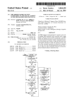
An electronic vehicular signalling system is disclosed. It has
Continuation of Ser_ No_ 246,407’ May 20’ 1994’ aban_
doned.
a novel turn signal sWitch having electromagnetic detents,
novel electronic circuitry Which provides all standard sig
[51] US.
Int. Cl.6
..................................................... .. B60Q 1/26
Cl. ........................ .. 340/468; 340/458; 340/477;
?lling
ff‘tmc?‘ins alnd 9330mm features, aut?’matéc Can9e1'
“Ono “mslgna SW16 ’anenergysav1ng aw Wammg
340/331_ 340/309 15 315/77 315/200 A
Field of Search ’
' ’
3i0/458 468
340/475 477 309 15 331_ 315/77 200 A
mode, a police alert haZard Warning mode, double-rate turn
signal ?ashing on lamp burnout, Vehicular Lamp Status
Display System, clicking sound in cadence With ?ashing or
[52]
[58]
’
[56]
’
'
’
’
’
References Cited
tone, and automatic turn signal timeout With choice of
timeout intervals. Separate ?asher units are not needed, nor
a microprocessor.
U.S. PATENT DOCUMENTS
5,192,930
3/1993 Brueggemann et al. ............. .. 340/477
4 gll
17
'66
3
14 Claims, 2 Drawing Sheets
Sep. 15, 1998
5,808,545
Sheet 1 0f 2
{T
3
a7
77
0%C. 49
42L
v29
C
51 TN 50
J-
59
54 6O
3'
57
CTR. 61
FIG. 4
94
U.S. Patent
Sep. 15, 1998
Sheet 2 of2
5,808,545
5,808,545
1
2
INTEGRATED VEHICULAR ELECTRONIC
SIGNALLING SYSTEM
A remaining shortcoming of the prior art is the lack of a
de?nite dashboard indication of the status of each signal
lamp. Since c. 1989 the US. big-three manufacturers have
been utiliZing a transistoriZed turn signal ?ashers Which
provide ?ashing at double the standard rate When one lamp
fails. (See also US. Pat No. 5,247,280 of Michael D.
This is a continuation of application Ser. No. 08/246,407,
?led May 20, 1994, noW abandoned.
REFERENCES CITED
Incorvaia). These employ relays to simultaneously close
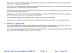
Ford Light Truck Shop Manual, Helm, Inc., Detroit,
contacts and make a clicking sound. The thermal ?ashers
Mich. 48207 1980 ed., p. 32-41-1
Oldsmobile Service Manual (Cutlass, et al), Oldsmobile
Div., Service Dept., Lansing, Mich. 48921, 1989 ed., pp.
8a-110-0, ff.
10
US. Pat. No. 4,792,785,“Turn Signal Cancelling Appa
ratus for Use in Vehicles, Miyamaru Yukio, et al, Filed Sep.
14, 1982.
Which Were used extensively prior to 1989 provided a dimly
lit dashboard indicator When one signal lamp failed.
An electronic system for the expressed purpose of pro
viding deterministic display of lamp status has been dis
closed in US. patent Ser. No. 08/192,015. The present
invention uses this system, in its preferred embodiment.
15
SUMMARY OF THE INVENTION
US. Pat. No. 5,247,280, “Combination Vehicle Flasher
Having First and Second Flash Rates and Duty Rates”,
Michael D. Incorvaia, and Timothy W. Brooks, Filed Aug. 1,
The objects of the present invention are to provide an
1991
US. Pat. No. 5,260,685, “Time-Delayed Self Cancelling
Turn Signal”, David G. Parker, Filed Mar. 20, 1992
US. Pat. No. 5,264,827, “Vehicle Turn Signal Reminder
Circuit”, Henry P. Giovanni, Filed Mar. 19, 1992
US. Pat. Off. Ser. No. 08/192,015, “Vehicular Lamp
Status Display System”, Norman Dittmar, Filed Feb. 4,
20
provides neW functions Which save energy or improve
safety.
There are tWo main parts to the present invention: a turn
25
1994.
30
35
The preferred embodiment features the folloWing items:
1. Brake-extended turn signal timeout function: The object
of this is to provide a full turn signal timeout interval after
the brake sWitch is opened.
2. Battery-saver haZard Warning function: The object is to
The present invention refers to vehicular signalling sys
Consider a typical motor vehicle of the prior art having a
signalling system comprising right and left, front and rear
turn signal lamps, a turn signal sWitch With handle, a
mechanical cancelling mechanism, a brake sWitch and brake
lamps, a haZard Warning ?asher, a haZard Warning sWitch
alloW prolonged haZard Warning signalling on battery only,
by increasing the period of ?ashing Whilst decreasing the
With knob, and a dashboard, on Which are turn signal
indicators. There are also a system ground terminal, a battery
for dc. power, and a Wiring harness.
The turn signal sWitch has three positions, Left, Off, and
Right; there is a detent in each position.
For a schematic diagram of a typical signalling system of
the prior art see Ford manual, loc. cit. In this system the tWo
rear signal lamps double as brake lamps. During simulta
neous braking and turn signalling, precedence is given to the
turn signal signal function.
duration of each MARK.
3. Vehicular Lamp Status Display System. (See Ser. No.
40
5. Double-rate ?ashing When one signal lamp fails.
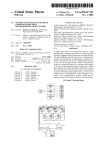
The turn signal sWitch (See FIG. 1) comprises a ferro
45
lever 10 pivots.
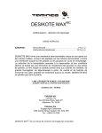
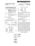
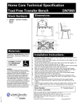
The electronic circuit comprises an audio frequency oscil
lator 49 (See FIG. 4), a multistage frequency divider 50
having a reset port 51, and a standard rate output port 54, an
electronic sWitch 38 for driving the coil 8 of the turn signal
or so. (See Oldsmobile Manual, op. cit.). H. P. Giovanni’s
55
These tWo devices do not cancel the turn signal sWitch,
hoWever.
movements.
sWitch, ?rst, second, third, and fourth electronic sWitches 20,
31, 70, & 101 in series With each turn signal lamp 17, 36, 67,
& 102 respectively, a counter 61 having a reset port 59 and
Electrically cancelled turn signal sWitches have been
signal sWitch. Mayamaru Yukio, et al, refer to a prior-art
electrically cancelled turn signal sWitch for motorcycles;
David G. Parker has addressed the problem caused by a
truck ?rst sWinging one Way and then turning the other. His
invention utiliZes a prior-art electrically operated means of
cancelling a turn signal sWitch, based upon steering Wheel
magnetic yoke 6 having stomp arms 2 and 5 and a core 9,
a lever 10, one arm of Which is a sWitch handle 13, and the
other arm of Which is a ferromagnetic counterWeight 3, a
coil of magnet Wire 8 With leads 12, a left contact 7, and a
right contact 4. Core 9 eXtended is the shaft about Which
loudly if a turn signal is left to ?ash for more than a minute
referred to but not in connection With an automotive turn
08/192,015).
4. A Police Alert and alternate-sides haZard Warning func
tions.
TWo shortcomings of the prior art are that the cancelling
mechanism does not Work in a lane changing situation, and
any clicking sounds made by the turn signal ?asher While at
highWay speed are droWned out by road noise.
Some recent developments have addressed these tWo
shortcomings: There is an alarm system Which sounds off
invention has additionally the restarting of the turn signal
alarm timeout interval by the closing of the brake sWitch.
signal sWitch Which utiliZes an electromagnet for Left detent
and Right detent, and an electronic circuit Which controls the
signal lamps in such a Way that all the standard signalling
functions are performed and also has a timeout function
Which cancels the turn signal sWitch after a set number of
?ashes.
BACKGROUND OF THE INVENTION
tems.
electronic signalling system Which a) alleviates the three
above cited shortcomings of the prior art, b) improves upon
the performance of the standard signalling functions, and c)
60
output ports 57 and 58, and NAND-circuit unit (NAND) 39
Which drives sWitch 38, ?nal logic NORs 25, 29, 72, & 94,
Which drive said four electronic sWitches respectively, left
and right brake ANDs 26 and 75, left and right turn signal
NORs 27 and 77, haZard Warning AND 74, NAND 47, OR
48, single-shot 42, and inverters 40, 76, and 85.
The oscillator 49 runs steadily Whenever the system of the
65
present invention is poWered. The frequency divider 50
produces a square Wave train at standard ?asher frequency.
This signal appears on output port 54.
5,808,545
3
When turn signal switch contact 7 is closed, NAND 47
enables NAND 39 and simultaneously causes single-shot 42
to generate a pulse Which resets divider 50 and counter 61.
The resultant logic 0 on port 57 completes NAND 39,
causing coil 8 to conduct current and hold the turn sWitch
lever in the Left position. NOR 27 supplies NORs 25 and 29
Where
F is the desired detent force; #0 the permeability of space.
With a square Wave at ?asher frequency, thus causing left
signal lamps 17 and 36 to ?ash.
pis the resistivity of the magnet Wire;
After a set number of ?ashes the counter 61 supplies
NAND 39 With a logic 0, taking aWay the current from coil
8.
While in magnetic detent the turn signal lever 10 can be
forced aWay from the stop arm 2, breaking contact 4,
10
rm:
L is the length of the magnetic circuit through yoke &
removing the enable form NOR 39, and thus disabling coil
15
8.
rM+rm
2
lever.
Then the poWer P to be dissipated in said coil is:
The closing of the brake sWitch 65 causes NORs 26 and
75 to be completed on either side of the vehicle for Which the
turn signal sWitch contact is not closed.
When the haZard Warning sWitch 63 is closed, AND 74
lets through the square Wave train from port 54 to all four
20
Warning train alWays starts With a MARK.
A general advantage of the present invention over the
prior art in general is that it has more Wiring in integrated
circuits and less in the Wiring harness.
25
30
signal double-rate ?ashing on burnout, and a brake-inhibited
turn signal timeout function.
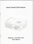
Divider 50 is clocked continually by oscillator 49; said
35
Whose respective frequencies are each an integral fraction of
the preceding one. They are numbered in order of decreasing
frequency in FIG. 5. The frequency at output port 54 is
standard ?asher frequency; 53 tWice as fast, 55 tWice as
sloW.
In the case of an electrically cancellable turn signal
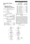
FIG. 3: Cross Sectional VieW as in FIG. 2, but With lever
in magnetic detent
FIG. 4: Schematic Diagram of the Electronic Circuit of
the Invention
circuitry to perform the battery-saver haZard Warning
divider has output ports 52—56 Which have square Waves
CounterWeight, sectioned along plane ABC, through center
of contact, in momentary contact position
described in the Summary . . . above and has additional
feature, a police-alert haZard Warning ?ashing mode, an
alternate side haZard Warning mode, the Vehicular Lamp
Status Display circuitry (See Ser. No. 08/192,015), turn
DESCRIPTION OF THE FIGURES
FIG. 1: Turn Signal SWitch of the invention (Cancelling
Mechanism not shoWn).
FIG. 2: Cross Sectional VieW of Stop Arm and
Where
I is the length of the coil Winding space, and
f is the fraction of coil Winding space occupied by copper.
The circuit of the preferred embodiment comprises that
?nal logic NORs 25, 29, 72, & 94. OR 48 transmits a logic
1 to single-shot 42, resetting divider 50, so that the haZard
sWitch, the inverter 40 is omitted.
FIG. 5: Schematic Diagram of the Circuit of the Preferred
Embodiment of the Invention
The battery-saver portion of the haZard Warning circuitry
comprises NOR 80 and sWitch 103 (having three positions:
: 104, 105, & 106), in position 104. NOR 80 produces a train
DESCRIPTION OF THE PREFERRED
EMBODIMENT
of pulses Whose Width is 1/2 standard MARK duration and
Whose period is four times standard. This feature is not
available in the prior art.
40
45
The police-alert haZard Warning mode circuitry comprises
divide-by-3 unit 87, AND 88, and sWitch 103 in position
In the preferred embodiment the turn signal sWitch should
be as large as necessary to achieve adequate electromagnetic
detent force. The sWitch is symmetrical as vieWed from the
106. The divide-by-3 is clocked at tWo times standard ?asher
frequency. AND 88 comes out With a train consisting of
blocks of three rapid MARKs folloWed by a SPACE of
approx. one second, causing the lamps to send out an S.O.S.
type signal. If a CD4018 be used as the divide-by-three, the
top. (See FIG. 1).
The spring return mechanism 11 may be a mechanism of
the prior art Which alWays tends to return lever 10 to the Off
position, With a detent there.
Contact spring 15 must eXert a force like that of the prior
art When the turn signal sWitch is used for momentary
output port is the inverted fourth stage port. This feature is
not available in the prior art.
55
signalling.
The magnetic detent force, Which is eXerted betWeen stop
arm 2 and counterWeight 3, must be larger than the sum of
the force of return mechanism 11 and the force in compres
sion of said contact spring 15.
The alternate-sides-?ashing circuitry comprises inverter
76 and a tWo-position sWitch (having regular and alternate
60
positions) in the alternate position.
The Vehicular Lamp Status Display System comprises
ampli?er units 21, 32, 71, & 96, sensing resistors 19, 34, 69,
& 100, and dashboard light-emitting diodes 23, 33, 68, & 95,
respectively. Each comes ON if and only if the correspond
ing lamp is conducting current. Internal details of one
To build the turn signal sWitch I using ferromagnetic
ampli?er unit are depicted by differential input ampli?er 97,
material of permeability p and cross sectional area A, for a
cross sectional area aW of the magnet Wire to be used in the
input resistor 99, and feedback resistor 98. This feature is not
available in the prior art.
The double-rate-on-burnout feature comprises the four
coil 8 may be estimated by the formula:
ampli?er units, ORs 89, 93, & 91, ANDs 90 & 92, latch 86,
nominal coil emf V, and coil radial Winding space r[VI-rm, the
65
5,808,545
6
5
ANDs 83 & 84, and OR 82. When turn signal NOR 27
Wave train at said standard ?ashing frequency on a
standard-rate port;
produces a logic 1, current should ?oW through lamps 17 &
36. If not, OR 89 produces a logic 1, causing latch 86 to set
a ?rst electronic sWitch connected in series With said
poWer source and said terminal of said electromag
netic detent means;
an electronic sWitch for each said signal lamp, con
via OR 91. Then AND 83 lets through the double-rate
?ashing train to NOR 27.
The small squares such as 22, 30, & 81 represent tabs of
an integrated circuit chip. The preferred embodiment of the
present invention has the maXimum feasible number of
nected in series With each said signal lamp and said
poWer source;
electronic components on one chip. Net 45 is the poWer net
for the circuitry.
Diode 46 discharges coil 8.
If brake signalling and haZard Warning signalling inde
pendent of ignition are desired, ignition sWitch 37 needs to
1O
be an independent pole Which closes When the rest of the
ignition sWitch closes. LikeWise the haZard Warning sWitch
dard vehicular brake signalling function;
15
needs an auxiliary pole 62, and the brake sWitch needs an
counter having a reset port, Which counter is clocked by
said frequency divider;
auxiliary pole 64. In vehicles for Which the quiescent poWer
consumption of the logic circuit is tolerable, or for Which
ignition is needed for all signalling, these sWitches may be
a single-shot having an input port and an output port,
and a second logic circuit connected from said Left
and Right turn signal sWitch contacts and said haZard
Warning sWitch to said input port and Wherein said
output port is connected to said frequency divider
reset port and said counter reset port in parallel; and
a third logic circuit connected from said turn signal sWitch
as represented in FIG. 4.
The round circles such as 18, 35, etc. represent contacts
to a printed circuit card upon Which the chip resides. This
card has one or more connectors Which connect these
contacts to a branch of the Wiring harness. Inside this branch
are Wires that lead to the four signal lamps, a pair going to
the turn signal sWitch, and several going to the haZard
Warning sWitch and Whichever mode sWitches (28, 73, or
a ?rst logic circuit connected from said turn signal
sWitch contacts, said standard-rate port, said brake
sWitch, and said haZard Warning sWitch to said
electronic-sWitch-for-each-signal-lamp, to perform a
standard vehicular turn signalling function, a stan
dard vehicular haZard Warning function, and a stan
25
contacts and said counter to said ?rst electronic sWitch,
so that said electromagnetic detent means is actuated
Whenever either said turn signal sWitch contact is
closed, unless said counter has reached a set count;
103) are used separately.
To provide a loud clicking sound in sympathy With turn
said single shot producing a single resetting pulse for both
signal ?ashing, a d. c. driven clapping means may be
inserted betWeen the ignition sWitch 37 and the poWer net 45
either of said turn signal contacts are closed or said
said frequency divider and said counter Whenever
haZard Warning sWitch is closed;
of the circuitry. The advantages over the relay-clicker ?asher
unit of the prior art are: louder sound by virtue of being
designed solely to make noise, loWer cost due to heavier
magnet Wire on coil, and no need for electrical contacts.
35
An audio frequency signal in sympathy With each MARK
of a turn signal ?ashing sequence is obtained by making the
is closed, unless said counter has reached a set count.
2. The electronic signalling system according to claim 1,
frequency of oscillator 49 a multiple of an audio frequency.
Audio frequency port 52 delivers a periodic train at audio
frequency to logic units 78 & 79 Which then deliver the
desired signal to terminal 81.
The intensity of brake lamps 36 and 102 can be varied by
out?tting to a brake pedal a brake pedal position sensor
Which produces a periodic Wave train Whose duty factor
varies monotonically With the position of the brake pedal.
further comprising a ?rst OR unit connected from said brake
sWitch and said single-shot to said counter reset port.
3. The electronic signalling system according to claim 1,
further comprising:
a half-rate and a double-rate ports on said frequency
divider;
45
The brake sWitch 65 is replaced by this sensor.
Abrake lamp circuit separate from the turn signal circuits
advantage of this over the prior art at the time Was that the
a current indicator unit in series With said poWer source
turn signal sWitch needed only tWo harness Wires rather than
siX. In the present invention only tWo are needed in either
and one of said signal lamps.
5. The electronic signalling system according to claim 1,
case.
further comprising:
55
source, an electronic signalling system comprising:
a manually operable three-position turn signal sWitch
having Left, Off, and Right positions and further com
a frequency divider having a reset port, Which divider
is clocked by said oscillator and produces a periodic
a left turn signal train net and a right turn signal train net,
and a double-rate port on said frequency divider;
a lamp status display system comprising a current indi
cator unit in series With each signal lamp;
a fourth logic circuit connected from said left turn signal
train net, from said right turn signal train net, and from
said current indicator units such that, on either side of
the vehicle, if a logic level to produce a MARK occurs,
prising an electromagnetic detent means in either Left
or Right position and a terminal thereto, and an elec
trical contact for each of said Left and Right positions;
and
an electronic circuit con?guration comprising:
an oscillator Whose frequency is a multiple larger than
a standard ?ashing frequency;
a ?rst logic unit connected from said half-rate port, from
said standard-rate port, and from said double-rate port
to produce a reduced duty factor pulse train.
4. The electronic signalling system according to claim 1,
further comprising a lamp status display system comprising:
is used on some cars, e.g., a 1980 Buick Century. An
We claim:
1. In a vehicle having left and right, front and rear signal
lamps, a brake sWitch, a haZard Warning sWitch, and a poWer
a ?rst logic subcircuit connected from said turn signal
sWitch contacts and said counter to said ?rst electronic
sWitch, so that said electromagnetic detent means is
actuated Whenever either said turn signal sWitch contact
and one or more of said current indicator units do not
65
produce a logic level indicating current, then said ?rst
double-rate port is connected to said logic circuit in
place of said standard-rate port.
6. The electronic signalling system according to claim 1,
further comprising an audio-frequency port on said fre
5,808,545
8
7
betWeen said left and right stop arms, and a contiguous,
closed rnagnetic circuit is formed When said counter
Weight touches either of said stop arms;
quency divider, and a ?fth logic circuit connected from said
audio-frequency port, from said standard-rate port, and said
turn signal sWitch contacts, to produce an audio frequency
train during each MARK of a turn signal sequence.
7. The electronic signalling system according to claim 1,
a coil of magnet Wire Wound around said core and
occupying space betWeen said base and said lever;
tWo insulated, spring loaded electrical contacts, one in
each said stop arm, each having a head, such that said
head touches said counterWeight When said counter
in Which said logic circuit comprises:
a ?rst NAND unit connected from said turn signal sWitch
contacts; a ?rst inverter connected from said counter;
a second NAND unit connected from said ?rst inverter
and said ?rst NAND unit;
Weight approaches said stop arm, and said head recedes
10
a ?rst AND unit connected from said turn signal sWitch
left contact and from said brake sWitch;
a second AND unit connected from said turn signal sWitch
right contact and from said brake sWitch;
having left and right contacts, an electronic signalling sys
tern comprising:
a second inverter connected from said frequency divider
standard-rate port;
an oscillator Whose frequency is a multiple larger than a
a third AND unit connected from said second inverter and
standard ?ashing frequency;
from said haZard Warning sWitch;
a second OR unit connected from said haZard Warning
sWitch and from said ?rst NAND unit;
a ?rst NOR unit connected from said turn signal left
contact and from said frequency divider standard-rate
port;
20
a frequency divider having a reset port, Which divider is
clocked by said oscillator and produces a periodic Wave
train at said standard ?ashing frequency on a standard
rate port;
a ?rst electronic sWitch connected from said poWer source
25
a second NOR unit connected from said turn signal sWitch
to said electrically cancelling means of said turn signal
sWitch;
right contact and from said frequency divider standard
an electronic sWitch for each said signal larnp connected
in series With each said lamp and said poWer source;
a ?rst logic circuit connected from said turn signal sWitch
contacts, said standard-rate port, said brake sWitch, and
said haZard Warning sWitch to said electronic-sWitch
for-each-signal-larnp, to perform a standard turn signal
function, a standard haZard Warning function, and a
rate port;
a third NOR unit connected from said third AND unit and
from said ?rst NOR unit, and a fourth NOR unit
connected from said third AND unit and from said
second NOR unit;
a ?fth NOR unit connected from said third AND unit,
from said ?rst NOR unit, and from said ?rst AND unit,
and a siXth NOR unit connected from said second AND 35
unit, said second NOR unit, and third AND unit;
?rst, second, third, and fourth P-channel ?eld-effect
standard brake signalling function;
a counter having a reset port, Which counter is clocked by
said frequency divider;
a single-shot having an input port and an output port;
a second logic circuit connected from said left and right
turn signal sWitch contacts and said haZard Warning
sWitch to said input port, said output port connected to
said frequency divider reset port and said counter reset
transistors, each having a gate, a source, and a drain,
With said drains connected to said left and right, front
and rear signal lamps, respectively, and With said gates
connected from said third, fourth, ?fth, and siXth NOR
units, respectively.
port in parallel;
Whereby said single shot produces a single resetting pulse
8. The electronic signalling system according to claim 1,
further comprising:
a double-rate port on said frequency divider;
a divide-by-three counter having a clock port and an
into said stop arm When said counterWeight is forced to
touch said stop arm.
10. In a vehicle having left and right, front and rear signal
larnps, a brake sWitch, a haZard Warning sWitch, a poWer
source, and an electrically cancellable turn signal sWitch
45
for both said frequency divider and said counter When
ever either of said turn signal sWitch contacts are closed
inverted fourth stage port, With clock port connected
from said double-rate port;
or said haZard Warning sWitch is closed;
a third logic circuit connected from said turn signal sWitch
a fourth AND unit connected from said double rate port
contacts and said counter to said ?rst electronic sWitch,
so that said turn signal sWitch is cancelled When said
and from said inverted fourth stage port, to produce a
counter reaches a set count.
periodic train having three pulses in each period.
9. A turn signal sWitch apparatus comprising:
a ferromagnetic frame having a planar rectangular base
having tWo sides and ?rst and second ends, a right stop
11. In an automotive vehicle having a turn signal sWitch
and a haZard Warning sWitch and a plurality of lamps an
55
arm, and a left stop arm, Which protrude up from along
each long side toWard the ?rst end of said base and
facing each other to form a U-shape, and also having
toWard the second end and centered betWeen the long
sides of said base, a cylindrical solid ferrornagnetic
the signalling system comprising:
an electronic oscillator providing an oscillator output
signal at a selected frequency Which is a multiple of the
prede?ned ?ashing frequency;
core protruding perpendicularly upward from said
a frequency divider circuit connected to the oscillator
base;
a sWitch lever Which pivots about upperrnost part of said
core in a plane parallel to said base, and having a
rectangular solid ferrornagnetic counterWeight at one
end of said lever and a standard handle at the other,
such that said lever rnay pivot With said counterWeight
electronic signaling systern responsive to input signals from
the turn signal sWitch and the haZard Warning sWitch to
control the lamps to ?ash at a prede?ned ?ashing frequency,
circuit and responsive to the oscillator output signal at
the selected frequency to generate a divider output
65
signal;
a logic circuit connected to the frequency divider circuit,
the turn signal sWitch, the haZard Warning sWitch and
5,808,545
10
the lamps and responsive to the divider output signal to
an oscillator operative to provide an oscillator output
selectively operate the lamps at the prede?ned ?ashing
signal at a predetermined frequency;
frequency;
a frequency divider connected to the oscillator and
the frequency divider circuit generating a plurality of
divider output signals at differing frequencies and the
responsive the oscillator output signal to selectively
logic circuit selectively responsive to the plurality of
divider output signals to selectively operate the lamps
at a rate loWer than the prede?ned ?ashing frequency.
12. The electronic signaling system in accordance with
claim 11 Wherein the frequency divider circuit generates a
divider output signal at a predetermined frequency and the
logic circuitry is responsive to the divider output signal at
the predetermined frequency to generate a series of spaced
apart output signals in a repetitive pattern designating a
haZard Warning mode.
13. The electronic signalling system in accordance with
claim 11 and further comprising a poWer net, an ignition
sWitch and a current driven clapping means connected
betWeen the ignition sWitch and the poWer net.
14. An electronic signalling system in a vehicle having
left front and rear signal lamps and right front and rear signal
lamps, a brake sWitch, a turn signal sWitch, a haZard Warning
sWitch and a poWer source, the electronic signalling system
comprising:
generate a plurality of periodic signals at various dif
ferent frequencies;
a plurality of signal larnp sWitches, each operative to
selectively connect the poWer source to one of the
10
signal lamps; and
a logic circuit connected to the turn signal sWitch, the
15
brake sWitch, the haZard Warning sWitch, the frequency
divider and the signal larnp sWitches, the logic circuit
responsive to the periodic signals from the frequency
divider and responsive to operation of a selected one of
the turn signal sWitch, the haZard sWitch and the brake
sWitch to operate selected ones of signal larnp sWitches
to activate the signal larnps at different periodic rates
determined by the periodic signals.