1
l|||||||||||||ll||l||||||||l|||||||||||||||||||||l||||||l|||||||||||||||||||||||||||||||||
US 20040122281A1
(19) United States
(12) Patent Application Publication (10) Pub. No.: US 2004/0122281 A1
Fischell et al.
(54)
(43) Pub. Date:
MEANS AND METHODS FOR TREATING
Jun. 24, 2004
Publication Classi?cation
HEADACHES
(75)
Inventors: Robert E. Fischell, Dayton, MD (US);
(51)
Int. Cl.7 ..................................................... .. A61N 1/00
(52)
US. Cl. .............................................................. .. 600/13
David R. Fischell, Fair Haven, NJ
(US); Adrian R.M. Upton, Dundas
(CA)
(57)
Correspondence Address:
_
ABSTRACT
_
_
NEUROPACE, INC
Disclosed is a system and method for treatmg headaches.
1375 SHOREBIRD WAY
MOUNTAIN VIEW, CA 94043 (Us)
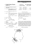
The system employs a self-contained, battery operated,
readily portable and easy-to-operate head-mounted mag
netic depolariZer to generate a transient or time-varying
(73) Assignee; NeuraLieve, Inc” Dayton, MD (Us)
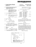
high-intensity magnetic ?eld into and around the user’s head
or neck. The magnetic depolariZer system can be used to
(21) Appl, No;
(22) Filed:
10/327,163
depolariZe the neurons of the brain and/or the trigeminal
Dec. 21, 2002
nerve. This type of neuronal depolarization has the capabil
ity for terminating migraine or other types of headaches.
22
l 'l
Patent Application Publication
Jun. 24, 2004 Sheet 1 0f 4
US 2004/0122281 A1
Patent Application Publication Jun. 24, 2004 Sheet 2 0f 4
US 2004/0122281 A1
Patent Application Publication Jun. 24, 2004 Sheet 3 0f 4
30
US 2004/0122281 A1
28\ [21
\
OFF 03;
19)
______
14‘\::_
g:-
/ \17
16
v
A l
A)»
<é———————-—
27
i
\/
7&1
K24
26
18A
18B
Patent Application Publication Jun. 24, 2004 Sheet 4 0f 4
US 2004/0122281 A1
Jun. 24, 2004
US 2004/0122281 A1
MEANS AND METHODS FOR TREATING
HEADACHES
placed over the scalp Which produced a high intensity, time
varying, magnetic ?eld. This magnetic ?eld produces an
electric current in the cortex of the human brain, Which can
FIELD OF USE
[0001] This invention is in the ?eld of medical devices for
the treatment of headaches by the application to the head
and/or neck of magnetic ?eld pulses.
BACKGROUND OF THE INVENTION
in turn produce certain effects (e.g., depolariZation and
discharge) of brain neurons. This type of system has been
given the name Transcranial Magnetic Stimulation (TMS).
If repetitive magnetic pulses are applied in this manner, it
has been given the name rTMS. In the journal Neurology
(Apr. 11, 2000, pp. 1529-1531) it has been reported by B.
Boroojerdi, et al, that rTMS at a rate of one pulse per second
human population. Migraine headaches cluster headaches,
can create a reduction of the excitability of the neurons of
the human visual cortex.
tension headaches and sinus headaches all cause serious pain
and even disability. Moreover, migraine headaches occur in
herein by reference, Fischell et al. describe the use of one
[0002]
There are many types of headaches that afflict the
approximately 11% of the population in the US. and West
ern Europe each year, and more than 2.5 million persons in
the US. have at least one day of migraine per Week.
Approximately 80 million additional people suffer from
other types of severe headaches in the US. Although neW
drug therapies emerge each year, some patients cannot ?nd
relief With any existing drug therapy, and some therapies
cause signi?cant side effects. A non-invasive, non-drug
method for preventing or treating migraine and other severe
headaches Would be a remarkable boon for those millions of
people all over the World Who suffer from these painful
experiences.
[0003] Migraine is Well knoWn to be a neurovascular
disorder that, in addition to pain, is characteriZed by auto
nomic nervous system dysfunction. Although the pain
mechanisms are not Well understood, it is believed that
actions in nerves in the head, brainstem and other tissues
cause blood vessels to dilate, Which causes pain, Which
causes further nerve activation. In particular the trigeminal
nerve and its associated autonomic nervous system function
seem implicated in this process for migraine and cluster
headaches. Disrupting this cycle can in some patients be a
key to treating migraine and perhaps other forms of head
ache. It has also been demonstrated that magnetic (TMS)
stimulation of the scalp causes alterations of the autonomic
balance in the heart as measured by changes in the beat-to
beat variability of the heart.
[0006]
In US. Pat. No. 6,402,678, Which is included
type of system for the prevention or treatment of migraine
headaches using one or more high intensity magnetic pulses
that depolariZe the neurons of the cerebral cortex. HoWever,
the Fischell et al patent does not describe speci?c systems
and methods for stimulation of the trigeminal nerve and its
associated autonomic nervous system function. Further
more, the Fischell et al patent makes no mention of stimu
lation of the neck or the use of a system that has one portion
of the system located on the patient’s head or neck that is
connected to a separate poWer source by electrical Wires.
SUMMARY OF THE INVENTION
[0007] The present invention is a system and method for
treating and preventing headaches that includes a device for
delivering one or more intense pulses of time-varying mag
netic ?eld to the head and/or neck of a person suffering from
headache. In the preferred embodiment, this device is non
invasive, externally applied, portable, self-contained and
under the control of the patient. The magnetic ?eld pulses
extend into the head and/or neck near the site Where the
device is applied in such a Way that the local neurons are
stimulated and depolariZed. The present invention includes
methods for using such a portable or non-portable device for
treating a variety of types of headache. In one embodiment
the time-varying magnetic ?eld created by the system
described above is suf?ciently intense so as to penetrate the
cranium and stimulate brain neurons and the Wrappings or
[0004] Some patients With migraine experience a distinct
meninges of the brain; this device is called a Transcranial
aura or Warning symptoms before the actual occurrence of
Magnetic Stimulator system (TMS). In another embodiment
the time-varying magnetic ?eld created by the system
the symptoms of the migraine headache. It is estimated that
approximately 40% of all migraine patients have some type
described above is less intense so that it can only penetrate
of aura that is a precursor of a migraine headache. Approxi
the skin and other surface tissues of the face, head and/or
mately half of these patients have a visual aura that typically
begins as a small pattern of scintillating colored lights that
neck and to stimulate surface nerves, such as the trigeminal
nerve; this device is called a Transcutaneous Magnetic
have the appearance of Wiggling Worms or multicolored
Stimulator (TcMS).
ZigZags. Over a time period of betWeen 20 and 30 minutes,
the pattern enlarges and fades until it extends into the
outermost portions of the visual ?eld. During this time
period, the patient might also completely lose part of his
visual ?eld. At the end of this visual aura, most migraine
patients have a severe headache that is often accompanied
by other symptoms such as nausea, vomiting and other
unpleasant feelings. Many migraine patients Who do not
have a visual aura have some other precursor of a migraine
that can be perceived from minutes to hours before the actual
start of the headache. Special techniques may be used to
treat patients With aura.
[0008] Recent literature in the ?eld of neurology suggests
that there is a correlation betWeen the trigeminal nerve and
headaches of various types. The trigeminal nerve is the large
cranial (?fth) nerve that supplies sensation to the face, much
of the scalp, meninges and the inside of the mouth. The
trigeminal nerve also supplies motor nerve ?bers for the
muscles of the jaW. Preliminary laboratory experiments
performed by Dr. Adrian Upton at McMaster University in
Canada have indicated that Transcutaeous Magnetic Stimu
lation (TCMS) of the trigeminal nerve can reduce or elimi
nate headache pain in a majority of the patients Who have
been treated With this therapy. The advantage of TcMS
[0005] In 1985, A. T. Barker, et al (Lancet, 1985, pp.
compared to rTMS or TMS is that much less poWer is
1105-1107) described the use of an electromagnetic coil
required to stimulate nerves located just beloW the skin (i.e.,
Jun. 24, 2004
US 2004/0122281 A1
transcutaneously) than is required to generate signi?cant
is required to produce a high intensity magnetic ?eld pulse.
electrical currents below the cranium and into the cerebral
cortex. Therefore, one embodiment of the present invention
is a means and method for stimulation of the trigeminal
While other shapes are possible, the electromagnet can be
formed in a racetrack, ?gure-eight shape, enclosed in an
appropriate casing, and equipped With a holding means such
nerve and its branches by means of one or more magnetic
as a Velcro strap, a handle or enclosed in a helmet. The
pulses that act upon the neurons of the trigeminal nerve.
length of the magnetic ?eld generator Would typically be
Both TMS and TcMS systems are referred to herein as
betWeen approximately 5 and 15 cm.
depolariZer systems. The depolariZer system is described as
self-contained if it can be battery operated, and it is
described as portable if it Weighs less than 5 kg.
[0009] It should be noted that in the limited clinical study
cited above, both TcMS and TMS have been successful in
stopping headaches that had lasted for many hours and that
Were not successfully treated With medication. The present
invention also includes the method of using a non-portable
[0013]
The poWer module Would typically contain a
rechargeable or replaceable (primary) battery to make the
system self-contained and to help make the system portable.
It Would provide the variety of voltages needed for the
system. The poWer system is expected to utiliZe a conven
tional AC adapter for providing direct poWer and/or for
recharging the batteries. It Would include the Well-knoWn
capabilities of rechargeable systems such as loW battery
TMS or TcMS device to treat or prevent headaches.
detection and safe recharging. The poWer module contains
the circuitry needed to deliver poWer to the magnetic ?eld
[0010]
generators capacitors.
One embodiment of this invention is a means and
method for the treatment of migraine headaches for those
patients Who experience a distinct aura before the actual
occurrence of the symptoms of the migraine headache. The
visual aura is a result of the spatial progression of a band of
[0014] The control module might be enclosed in the same
housing as the magnetic ?eld generator or it might be
separate. It Would typically contain the electronic devices
brain cells that are excited in that band typically across one
half of the brain’s occipital lobe. This band moves in an
anterior direction at the rate of approximately 2-5 mm per
needed to control the amplitude, number, frequency and
duration of the magnetic pulses delivered by the device. In
addition it Would include the patient operated sWitch that is
minute. It is believed that if the advancing band of excited
needed to turn the device on and off and deliver magnetic
neurons can be interrupted before the aura has completed its
pulses. It Would also include any display devices that Would
20 to 30 minute time duration period, the migraine headache
be needed by the patient to facilitate use of the TMS or
Will not occur. One Way to stop such an advancing band of
TcMS system.
excited brain neurons Would be by imposing a high enough
electric current through these neurons or neurons in the path
of the advancing band so that they become depolariZed and
therefore they are not available to support the spread of the
advancing band. One technique for electrically stimulating
these neurons is by using a TMS device, alone or in
combination With TcMS, that is placed over the occipital
lobe of the brain so as to stimulate the neurons. These
neurons Would then be in a refractory state Where they are
less likely to participate in passing on the “aura” event. The
device should be placed onto the patient’s head as soon as
possible after the patient becomes aWare of a visual (or any
other type) aura that is a precursor of a migraine headache.
For patients Whose aura originates from a region of the
cerebral cortex other than the occipital lobe, the depolariZing
device can be applied to the corresponding region of the
head.
[0011]
[0015] In one embodiment, the magnetic ?eld generator,
control module and poWer module are all contained in one
unit called a single unit depolariZer. In another embodiment
of the invention, the poWer module and portions of the
control module are in one portion of the system that is
connected to the magnetic ?eld generator by electrically
conducting Wires. Thus the head unit portion of the device
(Which Would be the magnetic ?eld generator) Would be
smaller and lighter With at least some of the source for
electric poWer being located remotely from the part of the
system that is placed on the head. The portion of the system
With the poWer module and all or part of the control module
might be designed to sit on a table top and Will be called the
table top unit. Note that other embodiments are possible. The
control module functionality can be split betWeen the head
unit and the tabletop unit in such a Way as to minimiZe the
Weight of the head unit. In general it is expected that the
The one pulse per second of rTMS described by
Boroojerdi, et al, Which Was proven to cause a reduction of
cerebral cortex excitability, could be applied to break up the
advancing band of excited neurons that is the cause of the
visible aura of a migraine headache. Furthermore, a single
TMS pulse or tWo to ten individual pulses spaced 2 to 100
seconds apart could also be used to depolariZe the neurons
on-off sWitch Would be located on the tabletop unit and the
pulse actuation sWitch could be located on the head unit.
[0016] Other embodiments of the device might include
other divisions of functionality betWeen the portion that is
placed on the patient’s head or neck and the portion that is
in a separate unit.
of the cerebral cortex to stop an aura from proceeding to a
[0017]
full bloWn migraine headache.
headaches, especially migraine headaches, by inducing a
[0012] The magnetic depolariZer system is expected to
transient electrical current in a portion of the patient’s cortex
by applying a very strong magnetic ?eld by means of a
depolariZer system that includes a magnetic ?eld generator
have a magnetic ?eld generator, a control module With
associated display devices, and a poWer module. The mag
netic ?eld generator is the source of the time varying
Thus, an objective of this invention is to treat
placed close to or onto the head or neck.
magnetic ?eld pulse. It includes an electromagnetic coil that
[0018]
is required to generate the magnetic pulses. It also typically
headaches, especially migraine headaches, by inducing a
contains the DC to DC converter and the capacitors that are
small transient electrical current in a portion of the patient’s
trigeminal nerve and associated nerves by applying a strong
discharged to provide the high level of electric current that
Another objective of this invention is to treat
Jun. 24, 2004
US 2004/0122281 A1
magnetic ?eld by means of a depolariZer system that
[0030] These and other objects and advantages of this
includes a magnetic ?eld generator placed close to or onto
invention Will become obvious to a person of ordinary skill
the head or neck.
in this art upon reading the detailed description of this
invention including the associated draWings as presented
herein.
[0019] Another objective of this invention is to prevent the
occurrence of a migraine headache by creating a short
duration, high intensity, time varying magnetic ?eld by
BRIEF DESCRIPTION OF THE DRAWINGS
means of a magnetic depolariZer system Whose magnetic
?eld generator is placed onto the scalp of a patient Who has
[0031]
an aura Which is a precursor of a migraine headache, the
portable magnetic depolariZer system for the treatment of
magnetic ?eld generator being adapted to cause depolariZa
tion of the neurons in the cerebral cortex Where the aura
originates.
[0020] Another object of this invention is to have the
magnetic ?eld generator placed by the patient onto his or her
head or neck at a speci?c location relative to the patient’s
cerebral cortex, head or neck.
FIG. 1 is a top vieW of a single unit, self-contained,
headaches.
[0032] FIG. 2 is a cross section of the magnetic depolar
iZer at section 2-2 of FIG. 1.
[0033] FIG. 3 is a cross section of the magnetic depolar
iZer at section 3-3 of FIG. 1.
[0034] FIG. 4 illustrates tWo positions of the magnetic
depolariZer on a patient’s head or neck.
[0021] Still another object of the invention is to have a
magnetic depolariZer system be self-contained and include a
poWer module, a magnetic ?eld generator, and control
[0035] FIG. 5 is a block diagram of the electrical circuitry
of the magnetic depolariZer of FIG. 1.
circuitry for creating a high intensity, time varying magnetic
?eld, Where settings of the system’s operating parameters
[0036]
are preset by a physician or by the manufacturer and the
system is operated by means of one or more patient operated
sWitches.
a head unit that is a magnetic ?eld generator designed to be
placed on the patient’s head or neck and a second part that
is has poWer and control modules forming a tabletop unit
that is connected by Wires to the head unit.
[0022]
Still another object of the invention is to have the
magnetic depolariZer system be poWered by a rechargeable
FIG. 6 is an alternative embodiment of the inven
tion having a ?rst part of the magnetic depolariZer Which is
battery.
[0037] FIG. 7 is a top vieW of a magnetic depolariZer
having an air core coil for creating the high intensity,
[0023] Still another object of this invention is to have a
self-contained magnetic depolariZer that can be held in the
patient’s hand and placed over a portion of the patient’s head
[0038]
or neck to stimulate either or both the trigeminal nerve and
the cerebral cortex With a time-varying magnetic ?eld as a
treatment for an ongoing headache.
[0024]
Still another object of this invention is to have a
self-contained device that provides a suf?ciently high inten
sity, time-varying magnetic ?eld pulse(s) to transcutane
ously stimulate the trigeminal nerve, thereby providing a
TCMS treatment for a headache.
[0025]
Still another object of this invention is to have a
portable, self-contained, magnetic depolariZer system that
consists of a magnetic ?eld generator adapted to be placed
onto the patient’s head by the patient and a poWer and
control module connected by Wires to the magnetic ?eld
generator, Which poWer and control module provides the
electrical poWer that is required to cause the magnetic ?eld
generator to generate a high intensity magnetic pulse.
[0026]
Still another object of this invention is for the
depolariZer system to be portable.
[0027] Still another object of this invention is for the
depolariZer system to have a display to help the patient in the
operation of the device.
[0028]
Still another object of the invention is for the
system to have control circuitry Which creates a time delay
betWeen pulses administered by the patient.
[0029]
Still another object of this invention is a method for
using TMS or TCMS from a non-portable or a portable
device for the treatment of a headache.
time-varying magnetic ?eld.
FIG. 8 is a cross section of the magnetic depolar
iZer at section 8-8 of FIG. 7.
DETAILED DESCRIPTION OF THE
INVENTION
[0039] FIG. 1 is a top vieW of a portable, self-contained,
magnetic depolariZer 10 that has the capability to provide a
high intensity magnetic ?eld pulse (or train of pulses) for
stimulation of the brain or for stimulation of the trigeminal
nerve. Stimulation of the cerebral cortex of the brain Will be
referred to herein as TMS, and transcutaneous stimulation of
the trigeminal nerve and of other surface nerves of the head
and neck shall be referred to herein as TcMS. Both forms of
stimulation can use the same type of device; e.g., any of the
devices that are shoWn in FIGS. 1-8. HoWever, TcMS
stimulation of the trigeminal nerve requires much less poWer
than the poWer required for stimulation of the brain by
means of TMS. Therefore, the portion of the system that is
to be placed on the patient’s head can be smaller and lighter
if only TcMS is to be applied.
[0040] The depolariZer system 10 includes a case 11, a
Velcro adjustable hand belt 12, an electronics module 13 that
includes circuitry that implements poWer module function
ality, magnetic pulse generator functionality and control
functionality. The system 10 also includes a battery 14, an
electromagnet 15, a recharging connector 16, an ON-OFF
sWitch 19 and a magnetic level setting sWitch 21. FIG. 5 is
a block diagram that illustrates the electrical connections
betWeen the electrical and magnetic components that are
shoWn in FIG. 1. The length of magnetic ?eld generator
electromagnet 15 Would typically be betWeen approximately
5 and 15 cm. The Width of the magnetic ?eld generator
Jun. 24, 2004
US 2004/0122281 A1
might be between approximately 3 and 10 cm and its height
in a direction above the skull (not including the Velcro hand
belt 12) could be betWeen approximately 1.0 and 5 cm.
[0041] FIG. 2 is a cross section of the self-contained
depolariZer 10 at section 2-2 of FIG. 1. The case 11 is
preferably a plastic shell that contains all the parts of the
depolariZer 10 except for the hand belt 12. The belt 12
consists of a top strap 12T and a bottom strap 12B; collec
tively being a Velcro adjustable hand belt 12. The tWo straps
12T and 12B are used by the patient to adjust the siZe of the
hand hole 22 through Which the patient’s four ?ngers 23 are
115 volts) to an appropriate DC voltage to recharge the
rechargeable battery 14. An adapter for utiliZing a car or boat
12-volt battery for operating the magnetic depolariZer sys
tem 10 is also envisioned. The recharge control circuit 17
provides Well knoWn poWer management capabilities of
rechargeable systems such as preventing overcharge, detect
ing loW battery voltage, alloWing operation Without battery
When the recharger is available, and timers to automatically
poWer off the system When appropriate.
placed as shoWn in FIG. 4. Also shoWn in FIG. 2 are the
[0045] When the patient is experiencing an aura of a
migraine headache or experiencing a headache itself, he or
she can throW the ON-OFF sWitch 19 to the ON position.
electronics module 13, the battery 14 and the electromagnet
15 having a Wire Winding 18A.
generate a high voltage for rapidly charging the capacitor 26.
[0042] FIG. 3 is a cross section of the magnetic depolar
iZer 10 at section 3-3 of FIG. 1. FIG. 3 shoWs the case 11,
the belt 12 having top and bottom straps 12T and 12B
respectively, the hand hole 22 and the electromagnet 15
having a ?rst coil Winding 18A and a second coil Winding
18B. Although the electromagnet 15 could use an air core
(i.e., a magnetic permeability of one) one preferred embodi
ment of the present invention uses a ferromagnetic core to
enhance the generation of the magnetic ?eld pulse. To
That Would cause the DC to DC converter 30 to come on and
There Would be a sufficient time delay (e.g., 3 to 10 seconds)
betWeen the time that the magnetic depolariZer system 10 is
turned on and the time that the ?rst magnetic pulse is
generated to alloW the patient to position the magnetic
depolariZer on the head or neck. When the control circuitry
28 senses that the appropriate capacitor voltage has been
reached, it moves the sWitch 27 from position “A” to
position “B” thus discharging the capacitor 26 through the
coils 18A and 18B of the electromagnet 15.
reduce the magnetic energy lost in a magnetic pulse, the core
of electromagnet 15 should be formed from a ferromagnetic
material having a loW hysteresis loss. Apreferred version of
the ferromagnetic core Would be formed from thin lamina
small number (typically one to ?ve) combinations of pulse
poWer, pulse train or single pulse and pulse train duration
tions to decrease eddy current losses during the magnetic
combination Will be selected by the patient using selector
pulse. Optimally the ferromagnetic core Would also have a
sWitch 21. Once the system is poWered on via sWitch 19 and
the treatment combination is selected via sWitch 21, the
control circuitry 28 Will control sWitch 27 to deliver the
desired pulse or pulse train. A tWo to four position sWitch 21
high saturation ?ux density and high permeability to create
the highest strength of the magnetic ?eld With the loWest
amount of energy. Such a ferromagnetic alloy Would be
selected from the group consisting of an iron-nickel alloy, a
nickel-iron-molybdenum alloy, pure iron or other alloys of
iron and/or nickel. An example of one such alloy is vana
dium permendur. Also, it is envisioned to use either lami
nations of such alloys or poWder metal cores or ferrite cores.
[0043] FIG. 4 illustrates tWo different positions for the
magnetic depolariZer system 10 as placed onto the head or
neck of a human subject. ShoWn in FIG. 4 are the cross
sections of the human ?ngers 23 shoWn betWeen the top of
the case 11 and beneath the Velcro belt 12. It is expected that
[0046]
At the factory or under the control of a doctor a
can be programmed into the control circuit 28. The treatment
can be used to select from the preprogrammed menu the
amount of energy stored in the capacitor 26 and to set a
corresponding number of energy levels for the magnetic
pulse. The sWitch 27 Would typically be a solid-state con
trollable sWitch such as a thyristor that is capable of repeat
able sWitching of a high electrical current in a feW micro
seconds. As previously described, the coils 18A and 18B
could have air cores or they could use a magnetically
permeable core.
[0047] A suf?ciently intense time-varying magnetic ?eld
the four ?ngers 23, excluding the thumb, Would be placed
pulse must be created that Would cause neurons to be
betWeen the top of the case 11 and the belt 12. The top and
depolariZed and thereby disrupt the start of a headache. For
TMS, the intensity of the magnetic ?eld at the surface of the
bottom straps of the belt 12, i.e., the straps 12T and 12B
respectively, Would be adjusted by the patient so that his or
her ?ngers 23 Would ?t snugly into the hand hole 22. It is
also conceived that the magnetic depolariZer system 10
could have a handle (not shoWn) that Would be held in the
patient’s hand as he or she places the device at some location
that the patient has found to be effective in treating a
headache. It Will be recogniZed that either a handle or belt
brain should be betWeen 0.1 and 5 Tesla. For TcMS the
intensity of the magnetic ?eld at 1 cm beloW the surface of
the scalp should be betWeen 0.1 and 5 Tesla. In both cases
the pulse Width of the magnetic pulse should be approxi
mately betWeen 0.1 and 5 milliseconds. The frequency rate
of the magnetic pulses (if more than one is used) should be
approximately betWeen 0.1 HZ and 500 HZ. With some
straps as described above, or a generic or patient-speci?c
patients a single, short duration pulse may be all that is
molded structure may be used as a positioner to ensure that
required. The magnetic pulses can be applied continuously
the depolariZer is placed properly over the patient’s trigemi
for a period of betWeen 0.1 and 50 seconds. By applying one
nal nerve. Other positioner structures are possible and Will
be apparent to a practitioner of ordinary skill in the art.
or more magnetic ?eld pulses to the neurons of the cerebral
[0044] FIG. 5 is a block diagram of the magnetic depo
lariZer system 10. The rechargeable battery 14 can be
recharged through the recharge control circuit 17 and recep
tacle 16 that can receive a plug from a conventional AC
adapter (not shoWn) that transforms AC line voltage (e.g.,
cortex and/or to the neurons in the scalp, many patients Will
be able to decrease the intensity and/or duration of a
migraine headache.
[0048] The circuitry for the magnetic depolariZer system
10 can also include message circuitry 24 that can be used (as
described in detail beloW) to inform the patient by audio or
Jun. 24, 2004
US 2004/0122281 A1
visual means hoW best to use the magnetic depolariZer
system 10 for treatment of a headache.
material Would optimally have a relatively high permeability
and high maximum ?ux density.
[0049] Although FIGS. 1 and 4 shoW a magnetic depo
[0053] Also shoWn in FIG. 6 is a Wire 44 and transformer
47 connected to a plug 45 for providing electric poWer for
the poWer and control module 41. As stated previously, this
recharger system could be used to recharge the batteries or
to poWer the system Without the battery in the circuit. The
plug 45 could be used to connect to conventional line poWer
lariZer system 10 With a battery, the system 10 could also be
operated by plugging into a receptacle at (typically) 115 or
230 volts AC. Such a system might or might not use a battery
as part of its circuitry.
[0050] FIG. 6 shoWs an alternative embodiment of a
headache treatment system 40 that utiliZes a tabletop unit
consisting of a plug 45, a transformer 47 connected by the
Wire to the 44 to the poWer and control module 41. The
tabletop unit is connected by an electrical Wire cable 42 to
the head unit Which is the magnetic ?eld generator 43. The
magnetic ?eld generator 43 Would typically include the
capacitor 26, the electronic sWitch 27 and the electromagnet
15 of FIG. 5. The poWer and control module 41 Would
typically include the battery 14, the ON-OFF sWitch 19, the
DC to DC converter 30, the receptacle 16, the recharge
control circuitry 17, message circuitry 24 and the part of the
control circuitry 28 having a magnetic pulse energy adjust
ment sWitch 21. By having only the capacitor 14, electro
magnet 15, part of the circuitry 28 to control the discharge
of the capacitor 26 and the sWitch 27 in the magnetic ?eld
generator 43, its Weight and siZe Would be considerably
reduced. Furthermore, the high current draWn by the Wind
ings 18A and 18B suggests that an optimum design has the
(e.g., 115 VAC). Alternately cord 44 Without the transformer
47 could be used to plug into a lighter receptacle of a car, or
it could be used With any other appropriate source of
electrical poWer. The poWer and control module 41 could
use primary batteries such as one to four cells, or it could use
rechargeable cells (e.g., nickel metal hydride or nickel
cadmium cells). Warning lights on the poWer and control
module 41 could be used to indicate When the battery is fully
charged and/or When battery poWer is getting loW.
[0054] FIG. 7 is a top vieW of an alternative embodiment
of the present invention that utiliZes an air core electromag
net to generate the required magnetic ?eld pulse. The
magnetic ?eld generator 50 of FIG. 7 Would be connected
to a poWer and control module (such as the poWer and
control module 41 of FIG. 6) by means of a Wire cable 52.
ShoWn in FIG. 7 is the outline of an electromagnetic coil 56
Within the magnetic ?eld generator case 54. Abelt 62 having
top and bottom straps 62T and 62B respectively Would be
shortest Wire connections betWeen the sWitch 27 and the
used to secure the magnetic ?eld generator 50 around the
capacitor 26. The energy lost by heating of the coils 18A and
patient’s ?ngers or a handle could be provided.
18B can also be reduced by making the coils out of silver
instead of copper or aluminum. Thus, the system 40 shoWn
in FIG. 5 can be made to have the lighter and smaller part
of the system be the head unit that is placed by the patient
onto his or her head. Since the charging of the capacitor 26
Would take place over a time period that is very long
compared to the time period of discharge of the capacitor 26
into the coils 18A and 18B, the electric current ?oWing
through the Wire cable 42 is reasonably loW. For example, if
the capacitor 26 discharges an average of 4,000 amperes into
the coils 18A and 18B in 0.5 milliseconds, and it takes 5
seconds to charge the capacitor, and if the ef?ciency of the
process is 50%, then the current through the Wire cable 42
is only 0.8 amperes. This comparatively loW current can be
carried by a copper Wire cable 42 that Would be compara
tively light and ?exible and Would not develop any appre
ciable heating. For stimulating only the trigeminal nerve, a
much loWer level of current Would typically be required.
[0051]
It is envisioned that there are several other Ways to
distribute functionality betWeen the poWer and control mod
ule and the head unit. For example, placing the sWitch 19 on
the head unit or placing the DC to DC converter 30 in the
head unit.
[0055] FIG. 8 is a cross section of the magnetic ?eld
generator 50 at section 8-8 of FIG. 7. ShoWn in FIG. 8 are
the case 54, the air core electromagnet 56, a capacitor 57,
electronics module 58 and the Velcro belt 62 having a top
strap 62T and a bottom strap 62B. It is also anticipated that
the functionality of the poWer/control unit could be incor
porated inside the case 54. In that case the depolariZer
system Would be contained in a single unit. The external
Wire connection Would only be needed for recharging or for
direct AC poWer.
[0056]
It is also envisioned to have some portion of the
system 10, 40 or 50 include electrical circuitry for providing
audio and/or visual directions for the use of the magnetic
depolariZer. These directions Would typically be set up at the
factory and could be a function of the setting of sWitch 21.
Alternately it is envisioned that system directions and pulse
de?nitions could be changed in the doctor’s of?ce by chang
ing a ROM or similar device or by doWnloading instructions
or data to a memory device. The message circuit 24 is
envisioned to include one or more small speakers and
screens to display status messages and instructions. The
stored audio directions could be played through the speak
ers. The visual directions for use can also be stored in a
sheet 46 of ferromagnetic material that could be surgically
placed betWeen the patient’s cranial bone and the patient’s
memory chip and presented by an LCD message panel. The
circuitry to provide such messages is represented by the
message circuitry 24 in FIG. 5. Typical directions could
[0052]
Also shoWn in FIG. 6 is a cross section of a thin
trigeminal nerve. The depolariZer system could be used With
include any one or all of the folloWing statements: (1) “the
or Without ferromagnetic sheet 46. Such a ferromagnetic
material sheet 46 Would alloW a much loWer energy to be
system has been turned on,” (2) “noW place the head piece
on your head,” (3) “the ?rst pulse has been delivered,” (4)
used for the magnetic pulse that causes depolariZation of the
“the second (or third, fourth, etc.) pulse has been delivered,”
(5) “the last pulse has been delivered,” (6) “the system is
noW turned off,” (7) “the battery voltage is loW, please
recharge noW,” and (8) “your system is not operating prop
trigeminal nerve. Examples of such a sheet of material
Would be 0.001 to 0.050 inches thick by approximately 0.1
to 2 inches Wide and approximately 1 to 5 inches long and
curved to ?t snugly over the cranial bone. The ferromagnetic
erly, please consult the user’s manual or call the phone
Jun. 24, 2004
US 2004/0122281 A1
number: 1-999-999-9999.” Status lights could be used
[0060] It is also envisioned that the magnetic depolariZer
instead of or in addition to the visual/audio directions
described above.
system as described herein could be used for the treatment
[0057]
It should be understood that in order to be useful to
of other disorders such as depression, pain, epilepsy, bi-polar
disease and other disorders of the brain.
a headache patient, the magnetic depolariZer system 10, 40
[0061] Various other rnodi?cations, adaptations and alter
or 50 must have several distinct characteristics that are
native designs are of course possible in light of the teachings
as presented herein. Therefore it should be understood that,
While still rernaining Within the scope and meaning of the
appended claims, this invention could be practiced in a
different from currently available systems for Transcranial
Magnetic Stimulation
Speci?cally, the inventive
concept of the present invention includes the fact that the
magnetic depolariZer system 10 and the battery operated
versions of the magnetic depolariZer systems 40 or 50 are
readily portable, self-contained, have preset operating
parameters that are not completely adjustable by the patient,
can be placed on the patient’s head by the patient and are
turned on and off by the patient. “Self-contained” is de?ned
herein as being battery operated. “Readily portable” can be
de?ned as having a Weight of less than 5 kg. The only
presently knoWn TMS equipment which is manufactured by
the CadWell company or the Magstirn company is operated
by a physician and not by a patient, has operational param
eters that are continuously adjustable by the physician as it
is being used (i.e., the parameters are not preset), has a
magnetic coil that is placed on a patient by an attending
physician, and since the entire system Weighs Well over 10
kg it is certainly not readily portable so as to be With the
patient Wherever he or she might need it.
manner other than that Which is speci?cally described
herein.
What is claimed is:
1. A magnetic depolariZer system for the treatment of a
headache of a human subject, the system comprising:
a readily portable rnagnetic depolariZer designed for
placement at a speci?c location onto the head or neck
of a human being, the magnetic depolariZer having at
least one electrornagnetic coil that is capable of pro
viding a time varying rnagnetic ?eld having a peak
intensity at some portion of the patient’s trigerninal
nerve of at least 0.1 Tesla and a positioner con?gured
to maintain the at least one coil in a desired position
relative to the trigerninal nerve; and
electrical circuitry connected to the magnetic depolariZer
for providing an electrical current through the at least
[0058]
To be most useful for its intended purpose, the
magnetic depolariZer system 10 Would have operating
one electrornagnetic coil, the electrical circuitry also
including a patient operated sWitch for turning on the
parameters that are preset by an attending physician using a
magnetic depolariZer system the system being turned
ROM replacernent strategy or any other Well knoWn rneans.
off by a timing means within the magnetic depolariZer
These operating parameters can include one or more of the
folloWing attributes: the peak intensity of the magnetic ?eld
at a distance of 1.0 cm beneath the magnetic depolariZer; the
time period of each rnagnetic pulse; the repetition rate of the
magnetic pulses and the total number of pulses to be
delivered When the magnetic depolariZer system is turned
system.
2. The system of claim 1 Wherein the electrical circuitry
of the magnetic depolariZer system includes a battery.
3. The system of claim 2 Wherein the battery is recharge
able.
4. The systern of claim 1 Wherein the electromagnetic coil
on. It should be understood that the TMS or TcMS device
of the magnetic depolariZer has a core comprising a ferro
might have as many as four preset levels that the patient can
select by means of the sWitch 21 located on a magnetic
magnetic material, the ferromagnetic material being selected
from the group consisting of alloys of iron, alloys of nickel,
iron-nickel alloys, iron-nickel-rnolybdenurn alloys, vana
depolariZer. Once these parameters are set, the patient Would
operate the magnetic depolariZer system by placing it on his
or her head and then turning the system on and then off after
the headache has been treated. It is also envisioned that the
system has only one operating level that is preset by the
factory or by the patient’s physician. It may be desirable for
the patient to turn the system on but a timer Would be used
to automatically turn the system off after a preset period of
time. The eXact level of intensity of the magnetic ?eld that
Would be set by the physician or by the patient Would be
determined by trial and error. That is, a level Would be
selected that provides the best and fastest relief for the
patient as that patient would determine from the actual use
of the magnetic depolariZer. That level may be reset from
tirne-to-tirne as the results in stopping headaches indicates.
[0059]
Since the aura of a migraine headache might occur
at any time, and since the patient may have only 20 minutes
to use the magnetic depolariZer system 10, each patient
Would Want to have a system in relatively close proximity.
For example, the patient Would Want to have the system at
home, and/or at Work, and/or in his or her car. The magnetic
depolariZer system would optirnally be sufficiently portable
to be taken With the patient on a vacation or on a business
trip.
diurn perrnendur, a poWder rnetal magnetic material, or a
ferrite material.
5. The system of claim 4 Wherein ferromagnetic material
core is larninated to decrease the eddy current loss When
creating the time-varying rnagnetic ?eld.
6. The system of claim 1 Wherein the electronic circuitry
is adapted to deliver a plurality of time varying rnagnetic
pulses.
7. The system of claim 6 Wherein at least one pulse of the
plurality of time varying rnagnetic pulses has a duration
between approximately 0.1 and 5.0 rnilliseconds.
8. The system of claim 6 Wherein the electronic circuitry
is adapted to deliver a sequence of pulses at a rate of between
approximately 0.1 HZ and approximately 500 HZ.
9. The system of claim 8 Wherein the sequence of pulses
is delivered over a time period of between approximately 0.1
second and approximately 50 seconds.
10. The system of claim 1, Wherein the electrical circuitry
is controlled by at least one operating parameter that is
preset by a physician.
11. The system of claim 1 Wherein the magnetic depolar
iZer system includes an instruction for informing the human
subject on hoW to operate the magnetic depolariZer systern.
Jun. 24, 2004
US 2004/0122281 A1
12. The system of claim 11 wherein the instruction
includes a message having a message type selected from the
group consisting of an audio message type and a visual
message type.
13. The system of claim 12 Wherein the message includes
at least one phrase selected from the group consisting of:
“the system has been turned on,”“noW place the head piece
on your head,”“the ?rst pulse has been delivered,”“the
second pulse has been delivered,”“the last pulse has been
delivered,”“the system is noW turned off,”“the battery volt
19. The method of claim 15 further comprising the step of
applying at least one magnetic pulse having a duration
betWeen approximately 0.1 and 5 milliseconds.
20. The method of claim 15 further comprising the step of
applying poWer to the magnetic ?eld generator With a
rechargeable battery.
21. The method of claim 15 further comprising the steps
of causing the patient to turn an ON-OFF sWitch ?rst to the
ON position and subsequently causing the patient to turn the
age is loW, please recharge noW,” and “your system is not
operating properly, please consult the user’s manual or call
a speci?ed phone number.”
sWitch to the OFF position.
22. The method of claim 15 further comprising the steps
of causing the patient turn an ON-OFF sWitch to the ON
14. The system of claim 1 further including a ferromag
netic piece placed betWeen the cranial bone and the patient’s
scalp, Wherein the ferromagnetic piece enhances the inten
sity of the time-varying magnetic ?eld used to depolariZe at
position and subsequently automatically deactivating the
least some of the neurons of the trigeminal nerve of the
human subject.
15. Amethod for the treatment of a headache, the method
comprising the folloWing steps:
sensing by a human subject that he or she is having a
headache; and
using a positioner to place a magnetic ?eld generator onto
the head or neck of the patient in a desired position
relative to the patient’s trigeminal nerve, by the patient
himself or herself, the placement being at a location
Where the magnetic ?eld generator can create at least
one magnetic ?eld pulse that has suf?ciently high
magnetic ?eld intensity for depolariZation of at least
some neurons of the trigeminal nerve.
16. The method of claim 15 further comprising the step of
turning the magnetic ?eld generator on to create a plurality
of time-varying magnetic ?eld pulses at the patient’s
trigeminal nerve.
17. The method of claim 15 further comprising the step of
applying a plurality of magnetic pulses at a rate betWeen
approximately 0.1 HZ and approximately 500 HZ.
18. The method of claim 15 further comprising the step of
applying a sequence of magnetic pulses for a time period
betWeen approximately 0.1 second and approximately 50
seconds.
magnetic ?eld generator after a time period.
23. The method of claim 15 further comprising the step of
causing a physician to set at least one operating parameter of
the magnetic ?eld generator.
24. A method for using a magnetic depolariZer system to
treat a headache in a patient, the method comprising the
steps of:
detecting an occurrence of a headache;
activating the magnetic depolariZer system; and
generating a time-varying magnetic ?eld having a peak
intensity at some portion of the patient’s trigeminal
nerve of at least 0.1 Tesla.
25. The method of claim 24 Wherein the magnetic depo
lariZer system is readily portable and self-contained.
26. The method of claim 24, Wherein the step of detecting
the occurrence of an onset of a headache comprises receiv
ing an input from the patient.
27. A self-contained, battery operated system for reducing
the intensity and/or duration of a headache by applying a
time-varying magnetic ?eld for stimulation of the trigeminal
nerve of a human subject, the system having an electromag
netic coil designed to create a peak magnetic ?eld intensity
onto the trigeminal nerve of at least 0.01 Tesla.