1
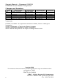
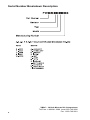
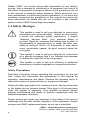
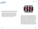
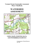
CONTENTS 1.0 Information ............................................................................... 5 1.1 Foreword ............................................................................ 5 1.2 Important Safety Notice ...................................................... 5 1.3 Safety Messages ................................................................ 6 1.4 System ................................................................................ 9 1.5 Auxiliary Air Tank................................................................ 10 2.0 Routine Maintenance ............................................................... 11 2.1 Maintenance Schedule ....................................................... 11 2.2 Start-up Procedure ............................................................. 12 2.3 Shutdown Procedure .......................................................... 13 2.4 Check oil level in oil/air separator tank ............................... 14 2.5 Check pressure supply valve ............................................. 16 2.6 Check compressor for damage .......................................... 17 2.7 Check air lines and hoses for damage ............................... 17 2.8 Change compressor oil ...................................................... 18 2.9 Change compressor oil filter ............................................... 19 2.10 Change compressor air filter ............................................ 21 2.11 Change coalescing filter ................................................... 23 2.12 Electrical ........................................................................... 24 2.13 Temperature Control Circuit ............................................. 25 3.0 System Diagnosis .................................................................... 26 4.0 Illustrated Parts Lists ............................................................... 28 4.1 Manifold and Filters ............................................................ 28 4.2 Oil/Air Separator Tank ........................................................ 29 4.3 Oil Cooler ............................................................................ 30 4.4 Compressor and Brackets .................................................. 31 4.5 Electrical Components ....................................................... 32 4.6 Hoses, Tubing and Harness ............................................... 33 VMAC – Vehicle Mounted Air Compressors Toll Free: 1-888-241-2289 Local: 250-740-3200 Fax: 1-250-740-3201 1 Owner’s Manual — Document 1930156 S700066 Lincoln Welder Compressor Changes and Revisions Version 000 A B C D E F Revision Details Revised by/date Original manual issue ECN 08-306 Service interval updates ECN 09-074 ECN 11-065: Service update ECN 12-030: UPDATES ECN 12-072: update pg. 32 SL May 29/2008 SL Feb 11/2009 SL May 21/2009 SL July 21/2009 MH Jun 09/2011 SAR 14 Feb 2012 MH 15May 2012 Approved by/date MH 11 Feb 2009 MH 27 May 2009 MH 21 Jul 2009 SM 12 Oct 2011 SC 30 Mar 2012 SM 16 May 2012 Implemented 12 Feb 2009 28 May 2009 21 Jul 2009 19 Oct 2011 30 Mar 2012 16 May 2012 Trademarks: S700066, and VMAC are registered trademarks of VMAC, Division of Mangonel Corporation Lincoln is trademarks of The Lincoln Electric Company Loctite is registered trademarks of Loctite Corporation Notice: Manuals and products are subject to change without notice Copyright 2009 The contents of this manual may not be reproduced in any form without written permission of VMAC PRINTED IN CANADA 2 VMAC – Vehicle Mounted Air Compressors Toll Free: 1-888-241-2289 Local: 250-740-3200 Fax: 1-250-740-3201 VMAC – Vehicle Mounted Air Compressors Toll Free: 1-888-241-2289 Local: 250-740-3200 Fax: 1-250-740-3201 3 Serial Number Breakdown Description 4 VMAC – Vehicle Mounted Air Compressors Toll Free: 1-888-241-2289 Local: 250-740-3200 Fax: 1-250-740-3201 1.0 Information 1.1 Foreword This manual provides maintenance, repair and troubleshooting instruction for the S700066 air compressor system. Proper and regular servicing provide continuing high performance and long life at low cost. For more information contact VMAC. KEEP THIS MANUAL WITH THE WELDING/AIR COMPRESSOR UNIT FOR USER REFERENCE 1.2 Important Safety Notice WHEN THE ENGINE IS RUNNING, EVEN WITH THE COMPRESSOR OFF, THE COMPRESSOR WILL PRODUCE UP TO 50 PSI (414 kPa) OF COMPRESSED AIR. NEVER WORK ON THE COMPRESSOR SYSTEM WITH THE ENGINE RUNNING. ALWAYS ALLOW PRESSURE TO DRAIN FOR A MINIMUM OF 5 MINUTES, OPEN THE SUPPLY VALVE AND TRIGGER ANY TOOLS ATTACHED TO DEPRESSURIZE THE SYSTEM BEFORE SERVICING THE COMPRESSOR AND COMPONENTS. The information contained in this manual is based on sound engineering principles, research, extensive field experience and technical information. Information is constantly changing with the addition of new models, assemblies and service techniques. If a discrepancy is noted in this service manual, contact VMAC prior to initiating or proceeding with service. Current information may clarify the matter. Any person with knowledge of such discrepancies who performs service and repair assumes all risks. Only proven service procedures are recommended. Anyone who departs from the specific instructions provided in this manual must first assure that their safety and that of others is not being compromised and that there will be no adverse effects on performance or the operational safety of the equipment. VMAC – Vehicle Mounted Air Compressors Toll Free: 1-888-241-2289 Local: 250-740-3200 Fax: 1-250-740-3201 5 Neither VMAC nor Lincoln will be held responsible for any liability, injuries, loss or damage to individuals or to equipment as a result of the failure of any person to properly adhere to the procedures set out in this manual or standard safety practices. Safety should be your first consideration in performing service operations. If you have any questions concerning the procedures in this manual or require any more information on details that are not included in this manual, please contact VMAC before beginning repairs. 1.3 Safety Messages This symbol is used to call your attention to instructions concerning your personal safety. Watch for this symbol; it points out important safety precautions, it means “attention, become alert!” Your personal safety is involved. Read the message that follows and be alert to the possibility of personal injury or death. Be alert; your safety is involved. While it is impossible to warn about every conceivable hazard, let good common sense be your guide. This symbol is used to call your attention to instructions on a specific procedure that if not followed may damage or reduce the useful life of the compressor. This symbol is used to call your attention to additional instructions or special emphasis on a specific procedure. Safety Precautions Read this information before operating the compressor for the first time. Follow the information and procedures in this manual for operation, maintenance and repair. Observe the following items to reduce the chance of personal injury or equipment damage. Follow all safety precautions for mechanical work. Moving drive belts or fan blades are an extreme hazard. Stay clear of all moving parts when the system is operating. Only qualified personnel should perform maintenance and repair on system components with the welder/compressor shutdown. Proper service and repair are important to the safety of the service technician and the safe, reliable operation of the equipment. Always use genuine VMAC replacement parts; do not use a substitute. 6 VMAC – Vehicle Mounted Air Compressors Toll Free: 1-888-241-2289 Local: 250-740-3200 Fax: 1-250-740-3201 The procedures described in this service manual are effective methods of service and repair. Some procedures may require the use of tools specially designed for a specific purpose. Anyone using a replacement part, service procedure or tool must first determine that neither their safety nor the safe operation of the equipment will be compromised by the replacement part, service procedure or tool selected. This manual contains various warnings, cautions and notices that must be observed to reduce the risk of personal injury during service or repair and the possibility that improper service or repair may damage the equipment or render it unsafe. Be aware that it is impossible to warn of all the possible hazardous consequences that might result from failure to follow these instructions. Fire and Explosion Hazards Fire in the compressor can cause an explosion and flame projection. Should this occur, there is potential for serious injury or death. Vaporized oil propelled by high-pressure air is an explosive mixture. You must observe the following when operating the compressor: constant vigilance is necessary around high-energy equipment be attentive for unexplained changes in operation parameters and record any changes never bypass or disable the oil temperature switch never expose the tank or compressor to extreme heat ensure that the air entering the compressor is free of flammable vapors Personal Hazards Follow all safe work practices. Wear the appropriate safety equipment. Do not breathe the compressor air. Vaporized oil is a respiratory hazard. VMAC – Vehicle Mounted Air Compressors Toll Free: 1-888-241-2289 Local: 250-740-3200 Fax: 1-250-740-3201 7 Always use the appropriate personal protective equipment, particularly eye and hearing protection when operating air-powered equipment. The compressor system is under sufficient pressure that a leak could force the oil/air mixture through the skin directly into your bloodstream. This will cause death. Never adjust or attempt to make any repairs to the compressor system while engine is running. Components and hoses under pressure could separate suddenly and fly out and cause serious injury or death. Never perform maintenance procedures on the system until the Welder/Compressor has been shut down for 5 minutes. After 5 minutes open the pressure supply valve to ensure the system is depressurized. Failure to depressurize the system could cause parts to separate explosively. Flying parts could cause serious injury or death. Oil/air mixture could be sprayed out with sufficient force to penetrate the skin, which could cause serious injury or death. The compressor and the compressor system gets very hot during operation, contact with the components or the oil can cause serious burns. Components and hoses under pressure could separate suddenly and fly out and cause serious injury or death. The auxiliary air tank must be drained before servicing any components in the compressor system. Pressure regulator and/or lubricator The compressor can produce air pressures up to approximately 150 PSI (896 kPa). It is the responsibility of the user to know the pressure and air flow requirements of the tools powered by the air compressor system. An appropriate air pressure regulator and lubricator can be externally installed to the outside of the pressure supply valve. Failure to regulate the air pressure could cause damage to the tool. 8 VMAC – Vehicle Mounted Air Compressors Toll Free: 1-888-241-2289 Local: 250-740-3200 Fax: 1-250-740-3201 1.4 System The compressor system is protected from over pressurization by a mechanical inlet control in the compressor that regulates air flow in response to the demand. There is also a 200 PSI (1,379 kPa) pressure relief valve in the oil/air separation tank to protect the system from over pressurization. If the oil temperature exceeds 290°F (143°C) the system is switched off, draining the high pressure air and reducing the load on the engine. VMAC certified and approved high performance synthetic oil is used to lubricate the compressor and is the only approved lubricant. Any other oil will void the warranty. The oil/air separator tank removes most of the oil from the compressed air and the coalescing separating filter removes the remaining oil. The oil is passed through a replaceable filter to remove contaminants. The compressor intake is equipped with a replaceable paper filter element. System Components Manifold Block Oil Filter Coalescing Separator Filter Oil Cooler Air Filter Compressor Inlet Control Valve Solenoid Valve Thermostat Oil Fill/Dipstick Drain Valve Pressure Relief Valve Oil/Air Separator Tank VMAC – Vehicle Mounted Air Compressors Toll Free: 1-888-241-2289 Local: 250-740-3200 Fax: 1-250-740-3201 9 1.5 Auxiliary Air Tank If an auxiliary air tank is to be used with this system the following setup MUST be followed. Failure to observe this procedure will result in damage to the system. 1. The auxiliary air tank must be connected to the supply valve. 2. The air line MUST have a one way check valve installed to prevent blow back from the auxiliary air tank into the compressor system. 3. The air line also MUST be connected as high as possible on the auxiliary air tank. 4. The auxiliary air tank MUST have a pressure protection valve calibrated for about 200 PSI (1379 kPa). 10 VMAC – Vehicle Mounted Air Compressors Toll Free: 1-888-241-2289 Local: 250-740-3200 Fax: 1-250-740-3201 2.0 Routine Maintenance Maintenance is a planned program which provides an orderly series of service and inspection procedures, together with cleaning. A well planned maintenance program lowers maintenance costs, reduces down time and can prevent possible accidents due to failed components. Shut down the Welder/ Compressor for 5 minutes. After 5 minutes open the pressure supply valve to ensure the system is depressurized. Torque Specifications STANDARD GRADE 8 NATIONAL COARSE THREAD Size 1/4 5/16 3/8 7/16 1/2 Foot-pounds (ft-lb) 9 18 35 55 80 Newton meter (N•m) 12 24 47 74 108 9/16 110 149 5/8 170 230 ¾ 280 379 STANDARD GRADE 8 NATIONAL FINE THREAD Size 3/8 7/16 Foot-pounds (ft-lb) 40 60 Newton meter (N•m) 54 81 1/2 90 122 5/8 180 244 ¾ 320 434 METRIC CLASS 10.9 Size Foot-pounds (ft-lb) Newton meter (N•m) M12 69 93 M14 104 141 M16 174 236 M8 19 25 M10 41 55 2.1 Maintenance Schedule The following maintenance schedule should be adhered to, to assure good performance and long service life. The hours indicated are those displayed on the hour meter. Service should be performed at the lesser of the two intervals, whichever occurs first. VMAC – Vehicle Mounted Air Compressors Toll Free: 1-888-241-2289 Local: 250-740-3200 Fax: 1-250-740-3201 11 Check the Illustrated Parts List for replacement part numbers or call VMAC. Every time before start up check the level of oil in the oil/air separator tank check pressure supply valve is in good working order check compressor and hoses for damage or wear check aftercooler drain collection bottle (if equipped) Extreme Environmental Service Intervals Change the following items as per intervals specified Stock (small) Air Filter Heavy duty air filter (optional) Compressor Oil Oil Filter Coalescent Filter = 50 hrs = 250 hrs = 250 hrs = 250 hrs = 250 hrs Note: Inspect air filter for contamination every 5 days whether compressor has been used, or not. Every 500 hours as displayed on the hour meter or 6 months which ever comes first (more frequently if used in dusty or extreme working conditions) change compressor oil change compressor oil filter change compressor air filter Every 1000 hours as displayed on the hour meter or 1 year which ever comes first change coalescing filter VMAC certified and approved synthetic oil must be used. Failure to use this special oil will result in damage to the compressor and will void the warranty 2.2 Start-up Procedure Read all the service procedures and safety warnings before operating the compressor. 12 VMAC – Vehicle Mounted Air Compressors Toll Free: 1-888-241-2289 Local: 250-740-3200 Fax: 1-250-740-3201 The unit must be level or must not exceed 35°, as higher angles will affect lubrication and oil and air separation. Never start the engine before the compressor system has fully depressurized. Starting or restarting the engine with pressure in the system causes extremely high loads on the internal components and may cause premature failure that may void any warranty claims. 2.2.1 Make sure the air operated equipment is securely connected to the supply valve and turned OFF. If air operated equipment is faulty, not securely connected, or not connected then excessive oil may be noticed in discharge air. 2.2.2 Place the engine main RUN-STOP switch in the STOP position. 2.2.3 Place the compressor ON-OFF switch in the OFF position. 2.2.4 Turn the air supply valve OFF. 2.2.5 Perform the “Before Start Up” checks in procedure 2.1. 2.2.6 Start the engine according to the starting instructions in the Lincoln Welder’s Owners Manual. Full air flow can only be achieved while the engine is operating at high idle. 2.2.7 Turn the compressor ON-OFF switch to the ON position. 2.2.8 Slowly open the supply valve. The compressor will supply compressed air as demand requires. 2.3 Shutdown Procedure 2.3.1 Turn OFF the air equipment connected to the supply valve. 2.3.2 Close the supply valve. 2.3.3 Turn the compressor ON-OFF switch to the OFF position. VMAC – Vehicle Mounted Air Compressors Toll Free: 1-888-241-2289 Local: 250-740-3200 Fax: 1-250-740-3201 13 2.3.4 Shutdown the engine according to the instructions in the Lincoln Welder’s Owners Manual. 2.4 Check oil level in oil/air separator tank The air compressor system holds 5 litres of oil which includes enough to fill the oil filter. The filter holds 0.3 litres of oil. The compressor holds about 0.5 litres of oil. The lower front panel (and hose lengths), have been designed to allow the tank to be accessed easily for servicing. If the front panel/tank is removed for oil change, ensure the tank is oriented correctly to enable correct oil levels to be read. 2.4.1 Unscrew the oil level dipstick and remove it. Take care not to damage the O-ring on the dipstick. 2.4.2 Wipe the oil level dipstick with a clean cloth or paper towel. 2.4.3 Insert the oil level dipstick and screw it all the way down, then unscrew and remove it. Oil Level Dipstick 2.4.4 Check the level mark the oil has reached on the oil level dipstick. 14 VMAC – Vehicle Mounted Air Compressors Toll Free: 1-888-241-2289 Local: 250-740-3200 Fax: 1-250-740-3201 2.4.5 Use a funnel inserted into the dipstick hole and pour in VMAC certified and approved synthetic oil. 2.4.6 Inspect the O-ring on the dipstick for abrasions or nicks. Replace the O-ring if damaged. Install the oil level dipstick and tighten it securely. 2.4.7 Start the engine following the start-up procedure number 2.2. VMAC – Vehicle Mounted Air Compressors Toll Free: 1-888-241-2289 Local: 250-740-3200 Fax: 1-250-740-3201 15 2.4.8 Turn the compressor switch on the control panel to the ON position. 2.4.9 Allow the system to pressurize. 2.4.10 Turn the compressor switch on the control panel to the OFF position. 2.4.11 Shutdown the engine and wait 5 minutes, then open the pressure supply valve to depressurize the system. 2.4.12 Check for oil leaks. 2.4.13 Repeat steps 2.4.3 through 2.4.13 until the oil level dipstick shows the oil level in the oil/air separator tank is in the operational range. 2.5 Check pressure supply valve Follow all safety precautions. 2.5.1 Check that the ball valve rotates freely. 2.5.2 Visually inspect the ball valve for damage, cracks or damaged threads. 16 VMAC – Vehicle Mounted Air Compressors Toll Free: 1-888-241-2289 Local: 250-740-3200 Fax: 1-250-740-3201 2.6 Check compressor for damage Follow all safety precautions. 2.6.1 Before starting the engine, open the service door and visually inspect the compressor for: cracks in the case oil leaks at the seams loose mounting bolts all the hoses and fittings are secure 2.7 Check air lines and hoses for damage Follow all safety precautions. 2.7.1 Trace all the airlines and hoses looking for chaffing against each other or metal edges. If chaffing is seen, use plastic convoluted loom to protect the area on the hose or airline. 2.7.2 Check that all the lines and hoses are secure. If loose hoses are seen, secure the hoses using tie straps. 2.7.3 Examine the hoses and air lines for cuts or cracks. 2.7.4 If any of the airlines or hoses show damage they should be replaced by an authorized VMAC Service Centre before operating the equipment. VMAC – Vehicle Mounted Air Compressors Toll Free: 1-888-241-2289 Local: 250-740-3200 Fax: 1-250-740-3201 17 2.8 Change compressor oil Follow all safety precautions. 2.8.1 Clean debris and dust from the area around the drain valve of the oil/air separator tank to prevent contamination. 2.8.2 Insert a hose over the oil/air separator tank’s drain valve outlet and open the valve to drain the oil into a container large enough to hold at least 1-1/2 US Gallons (6 litres). After the oil has drained, close the valve. 18 VMAC – Vehicle Mounted Air Compressors Toll Free: 1-888-241-2289 Local: 250-740-3200 Fax: 1-250-740-3201 Dispose of the oil in accordance with the Environmental Protection Laws in your location. 2.8.3 Remove and replace the oil filter at this time following procedure number 2.9. 2.8.4 Clean debris and dust from the area around the oil level dipstick of the oil/air separator tank to prevent contamination. 5 litres of VMAC certified approved synthetic oil is required to fill the system. 2.8.5 Unscrew and remove the oil level dipstick. Take care not to damage the O-ring on the dipstick. Use a funnel inserted into the oil level dipstick hole and pour in the required amount of VMAC oil. 2.8.6 Follow the oil level checking procedure in Section 2.4. 2.9 Change compressor oil filter Follow all safety precautions. Manifold Coalescing Filter 2.9.1 Clean debris and dust from the area around the manifold block and the filter to prevent contamination. 2.9.2 Remove the filter by turning it counterclockwise using a suitable filter wrench. VMAC – Vehicle Mounted Air Compressors Toll Free: 1-888-241-2289 Local: 250-740-3200 Fax: 1-250-740-3201 19 Check the filter to make sure that the threaded nipple did not unscrew with the filter. If it is in the filter, remove it carefully to avoid thread damage, coat the threads that go into manifold block with a small amount of Loctite blue and install it into the manifold block. Check Surface Threaded Nipple 2.9.3 Check the gasket-sealing surface of the manifold block for contamination, old gasket material or damage. Make sure the new filter is a VMAC filter, part number 9200039. This oil filter is a high pressure oil filter, not an automotive oil filter, which will rupture under high pressure. 2.9.4 Apply a thin coating of compressor oil to the filter sealing gasket. 2.9.5 Spin the filter onto the threaded nipple until the gasket contacts the sealing surface of the manifold block. 2.9.6 Tighten the filter an additional 3/4 to 1 turn to seat the sealing gasket. Never over-tighten the filter, as this may damage the seal or filter. 2.9.7 Follow the oil level checking procedure in Section 2.4. 20 VMAC – Vehicle Mounted Air Compressors Toll Free: 1-888-241-2289 Local: 250-740-3200 Fax: 1-250-740-3201 2.10 Change compressor air filter Follow all safety precautions. 2.10.1 Clean loose dust and debris from the area around the compressor and the filter cover to prevent contaminants from entering the system. Filter Retainer Filter Cover Inlet Control Valve 2.10.2 Remove the air filter cover retainer and the cover. 2.10.3 Immediately cover the compressor air intake with masking tape or a clean cloth to prevent contamination. Do not use compressed air or perform any other tasks around the compressor until the filter and cover are replaced. Never clean the filter element with compressed air as this will allow some contaminates into the compressor system. Always replace the air filter element. 2.10.4 Remove the filter element from the filter cover. Clean the inside of the cover with a clean, dry cloth. Do not use flammable solvents to clean the inside of the cover. If a solvent has been used rinse the cover thoroughly with water and dry it before installing the cover. Fire in the compressor can cause an explosion and fire. VMAC – Vehicle Mounted Air Compressors Toll Free: 1-888-241-2289 Local: 250-740-3200 Fax: 1-250-740-3201 21 Filter Retainer 2.10.5 Remove the masking tape or cloth from the compressor air intake. The new VMAC filter is round and must be flattened a little into an oval, make sure that the filter fits over the machined step on the intake housing. 2.10.6 Place the filter cover over the air filter and secure it with the cover nut. 22 VMAC – Vehicle Mounted Air Compressors Toll Free: 1-888-241-2289 Local: 250-740-3200 Fax: 1-250-740-3201 2.11 Change coalescing filter Follow all safety precautions. Manifold Coalescing Filter Do not use a screwdriver punched into the side of the filter, as this practice can damage the scavenging tube and screen. Manifold Check Surface Scavenging Tube Threaded Nipple Check the filter to make sure that the threaded nipple did not unscrew with the filter. If it is in the filter, remove it carefully to avoid thread damage, coat the threads that go into manifold block with a small amount of Loctite blue and install it into the manifold block. 2.11.1 Check the gasket-sealing surface of the manifold block for contamination, old gasket material or damage. VMAC – Vehicle Mounted Air Compressors Toll Free: 1-888-241-2289 Local: 250-740-3200 Fax: 1-250-740-3201 23 Make sure the new filter is a VMAC filter, part # 3600079. This is a high pressure filter. Use of other filters not rated to the required pressure may cause the filter to rupture. 2.11.2 Apply a thin coating of compressor oil to the coalescing filter sealing gasket and coat the end of the threaded nipple, as there is also a O-ring inside the coalescing filter. 2.11.3 Spin the filter onto the threaded nipple until the gasket contacts the sealing surface of the manifold block. 2.11.4 Tighten the filter an additional 3/4 to 1 turn to seat the sealing gasket. Never over-tighten the filter, as this may damage the seal or filter. 2.11.5 Check the oil level following the oil level checking procedure in Section 2.4. 2.12 Electrical The air compressor electrical system receives power from the main engine RUN-STOP switch, on the control panel, when the switch is in the RUN position. The compressor switch is turned to ON to start the compressor producing high pressure air. If the compressors oil temperature goes above 290°F (143°C) the thermostat will turn OFF the compressor and illuminate the ‘Compressor Protection’ indicator. 24 VMAC – Vehicle Mounted Air Compressors Toll Free: 1-888-241-2289 Local: 250-740-3200 Fax: 1-250-740-3201 2.13 Temperature Control Circuit Low idle operation When oil temperature is below 66[C] and engine is running at low idle, all thermal switches are open and the cooling fan is deenergized. As the oil warms past 66[C] thermal switch 1 closes. As the oil warms past 88[C], thermal switch 2 closes and the cooling fan remains de-energized. As a fail-safe feature if oil temperature rises to 105[C], thermal switch 3 closes and the cooling fan is energized. High idle operation When oil temperature is below 66[C] and engine running at high idle, all thermal switches are open and cooling fan is de-energized. As the oil warms past 66[C], thermal switch 1 closes. As the oil warms past 88[C], thermal switch 2 closes and energizes the fan. As oil cools below 66[C], thermal switch 1 opens and de-energizes the fan. K1 K2 87 THERMAL SWITCH 88° C (T2) K3 87 86 87A 85 86 87A 85 87 86 87A 85 30 30 30 BLUE TO T105 BLUE 18AWG BLUE TO T88 BLUE 18AWG THERMAL SWITCH 105° C (T3) BLUE TO T66 BLACK 18AWG TO LINE 405 TO 12V SUPPLY BLACK 18AWG BLACK 18AWG BLACK 18AWG RED YELLOW 18AWG G 14AW RED 18AWG RED TO T105 RED 18AWG RED 18A WG YELLOW 18AWG YELLOW 18AWG YELLOW TO T88 THERMAL SWITCH 66° C (T1) VMAC – Vehicle Mounted Air Compressors Toll Free: 1-888-241-2289 Local: 250-740-3200 Fax: 1-250-740-3201 25 3.0 System Diagnosis Problem diagnosis for the compressor system should follow sound, recognized practice. Quick, accurate diagnosis of problems is possible by; accurately identifying the problem by operating the system yourself, following safety practices determining possible causes for the problem by understanding how the system operates isolating the potential causes by accurate testing using the correct, recognized procedures performing proper repairs using the correct procedures outlined in this manual and the recommended replacements parts performing proper post-repair testing to ensure that the repairs were effective When performing problem diagnostics, do not use test practices that are potentially harmful to the people involved, or the equipment. Electrical testing should be performed according to the processes described in the troubleshooting charts and in conjunction with Lincoln’s Manuals. 26 VMAC – Vehicle Mounted Air Compressors Toll Free: 1-888-241-2289 Local: 250-740-3200 Fax: 1-250-740-3201 SYMPTOM Frequent relief valve operation Compressor does not run POSSIBLE CAUSE Pressure control line plugged or frozen System still at high pressure Defective relief valve Solenoid valve open High oil temperature Frozen solenoid valve Frequent overtemperature shutdown Low oil level Restricted oil lines Excessive oil in the air discharge Objectionable noise level Plugged oil filter Cooler not functioning or plugged Engine cooling system failure (high engine temperature) High ambient temperatures Oil temperature switch failure Coalescing separator failure Clogged scavenge line screen High oil level Operating angle in excess of 35 degrees from horizontal Air operated equipment is faulty, or not correctly connected to supply valve Excessive gear wear VMAC – Vehicle Mounted Air Compressors Toll Free: 1-888-241-2289 Local: 250-740-3200 Fax: 1-250-740-3201 CORRECTIVE ACTION Remove and clear the line Wait for system blow-down or bleed off all system pressure Replace the valve Check solenoid valve operation and replace if necessary See “frequent over-temperature shut-down” Temperatures below -10 C (14 F) can cause sticking, run the engine to warm up the engine compartment Check oil level with equipment on level ground Check for kinked or pinched lines Replace oil filter Replace or clean oil cooler Correct problem Reduce duty cycle Replace if defective Replace element Clean or replace Check oil level with equipment on level ground Reduce operating angle Test air operated equipment for proper operation and connect to supply valve Replace gearbox assembly 27 4.0 Illustrated Parts Lists 4.1 Manifold and Filters 2 14 15 13 4 10 9300070 - Assembly, Manifold Item 1 2 3 4 5 6 7 8 9 10 11 12 13 14 15 28 Qty 1 2 1 1 1 1 1 1 1 1 3 3 1 2 2 Part # 9300069 4900002 9200039 4900035 5000020 9300007 9300025 3600079 4900151 1200552 1510003 1570058 9300089 5830132 5830133 Description Manifold Machining Elbow, Steel JIC/O-ring, 1/2 3/4-16 Oil Filter, VR 3.250 Short Nipple, Steel Str. Thrd, 3/4 - 16 Elbow, Brass NPT-Poly, 1/8-1/4 Adapter Assembly, Scavenge Tube Oil Separator, Spin-On Connector, Steel, 45, 3/4-#12 ORB Male Bracket, Manifold Bolt, HHCS NC G8 PL, 5/16 X 1 Washer, Split Lock, 5/16 Fitting Modified O-Ring, Viton, #8 ORB O-Ring, Viton, #12 VMAC – Vehicle Mounted Air Compressors Toll Free: 1-888-241-2289 Local: 250-740-3200 Fax: 1-250-740-3201 4.2 Oil/Air Separator Tank 5 7 6 3 8 2 9300077 – Assembly, Tank Aluminum Item 1 2 3 4 5 6 7 8 9 10 Qty 1 1 1 2 1 1 1 1 1 1 Part # 4900033 5000089 4900079 5300009 5300011 9300090 3550691 3200360 3600054 9300076 Description Connector, Steel, NPT-JIC, 3/4-3/4 Connector, Brass, NPT-SAE, 3/8 - 1/2 Elbow, Steel,90 Deg,3/4 NPT-3/4 JIC Cap, Plastic, 1 1/16 CAP, Plastic, 3/4-16 Assembly, Dipstick, Compressor Oil Assembly, Thermostat 290F Valve, Modified (3600085) Valve, Safety, 200 PSI Weldment, Tank, Aluminum VMAC – Vehicle Mounted Air Compressors Toll Free: 1-888-241-2289 Local: 250-740-3200 Fax: 1-250-740-3201 29 4.3 Oil Cooler 3 17 6 13 2 14 15 3 7 8 12 10 5 11 9300068 – Assembly, Cooler Item 1 2 3 4 5 6 7 8 9 10 11 12 13 14 15 16 17 18 30 Qty 1 1 6 1 4 4 2 1 2 3 3 2 1 1 1 1 1 5 Part # 3600127 1200565 1500595 3550749 1510519 1550029 4900145 5000169 5300022 3550748 1540538 5830116 3500942 3500943 3500941 3500697 4900047 3500698 Description Cooler, #16 ORB Ports, Modified Bracket, Fan Rivet, Aluminum, Standard, Blind 1/4" Pusher Fan, Modified Bolt, HHCS NC G8 FL LK PL, 1/4X5/8 Nut, Nylock NC, 1/4 Fitting, #16 ORB Male X #8 JIC Male Plug, Hex Head, 1/4 NPT, Brass Plug, Plastic, Pull NPT, 1/2 Wiring Harness, S700066 Bolt, SHCS, M6 X 1.0 X 14, G8.8 O-ring, Viton, ORB -16 Thermal Switch, 88C Thermal Switch, 105C Thermal Switch, 66C Connector, Spade, Female, Insulated, 22-16 Elbow, Steel JIC, 1/2-1/2 Connector, Spade, Male, Insulated, 22-16 VMAC – Vehicle Mounted Air Compressors Toll Free: 1-888-241-2289 Local: 250-740-3200 Fax: 1-250-740-3201 18 16 4.4 Compressor and Brackets 1 2 4 5 3 6 P170024 – Assembly, Compressor, S700066 Item 1 2 3 4 5 6 Qty 1 1 1 1 1 1 Part # 9300071 5830004 P170023 1520573 1570058 1200559 Description Inlet Valve, S700066 O-ring, Viton, 3 1/8 ID x 1/8 Compressor, S700066 Bolt, HHCS, M8-1.25 X 20, G10.9 PL Washer, Split Lock, 5/16 Bracket, Compressor Brace VMAC – Vehicle Mounted Air Compressors Toll Free: 1-888-241-2289 Local: 250-740-3200 Fax: 1-250-740-3201 31 4.5 Electrical Components Wiring Harness, Solenoid and Connectors Item 1 2 3 32 Qty 2 1 1 Part # 5000020 4800591 3550811 Description Connector straight 1/8NPT - 1/4Poly Solenoid Valve with fittings Harness with Connectors VMAC – Vehicle Mounted Air Compressors Toll Free: 1-888-241-2289 Local: 250-740-3200 Fax: 1-250-740-3201 4.6 Hoses, Tubing and Harness 3 2 11 10 9 7 4 1 8 5 6 VMAC – Vehicle Mounted Air Compressors Toll Free: 1-888-241-2289 Local: 250-740-3200 Fax: 1-250-740-3201 33 1 2 3 1 1 18” 1752034 1752049 1710759 4 16” 1710714 5 1 1770079 6 7 1 17” 3550685 1710760 8 1 1772030 9 10 1 1 1770057 1751018 11 16” 1710622 34 Hose assembly - oil/air separator tank to oil cooler Hose assembly - oil cooler to manifold Tube 1/4 outside diameter - scavenge line (white) - manifold to compressor Tube 1/4 outside diameter - compressor ‘ON/OFF’ signal (red) - solenoid valve to inlet valve Hose assembly - discharge - manifold to supply valve Electrical harness Tube 1/4 outside diameter - signal (black) compressor to solenoid valve Hose assembly - supply - compressor to oil/air separator tank Hose assembly - oil/air separator tank to manifold Hose assembly - oil return - manifold to compressor Tube 1/4 outside diameter - system pressure (black) - manifold to inlet control valve VMAC – Vehicle Mounted Air Compressors Toll Free: 1-888-241-2289 Local: 250-740-3200 Fax: 1-250-740-3201