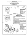
1
Installation / Operator Manual 1600 Series LED Remote Display Models 1601 & 1605 © 2007-2009 by Fairbanks Scales, Inc. All rights reserved 51157 Revision 6 10/09 Amendment Record 1600 Series LED Display Unit DOCUMENT 51157 Manufactured by Fairbanks Scales Inc. 821 Locust Kansas City, Missouri 64106 Created 05/2007 Revision 1 05/2007 Released Manual Revision 2 07/2007 Revision 3 08/2007 Included 1601 drawings and information Updated 1605 specifications Corrected drawings and verbiage. Revision 4 01/2008 Updated specifications and steps Revision 5 04/2009 Software Enhancements, added INTELL feature, Updated wiring charts 4169, 4170 & 51157-3 Revision 6 10/2009 Updated parts list Disclaimer Every effort has been made to provide complete and accurate information in this manual. However, although this manual may include a specifically identified warranty notice for the product, Fairbanks Scales makes no representations or warranties with respect to the contents of this manual, and reserves the right to make changes to this manual without notice when and as improvements are made. Fairbanks Scales shall not be liable for any loss, damage, cost of repairs, incidental or consequential damages of any kind, whether or not based on express or implied warranty, contract, negligence, or strict liability arising in connection with the design, development, installation, or use of the scale. © Copyright 2007-2009 This document contains proprietary information protected by copyright. All rights are reserved; no part of this manual may be reproduced, copied, translated or transmitted in any form or by any means without prior written permission of the manufacturer. 10/09 3 51157 Revision 6 Table of Contents SECTION 1: GENERAL INFORMATION .................................................................. 6 Introduction.......................................................................................................................... 6 Description........................................................................................................................... 6 Specifications ...................................................................................................................... 6 SECTION 2: INSTALLATION..................................................................................... 8 General Service Policies ..................................................................................................... 8 Phases of Installation...................................................................................................................... 8 Conferring with Our Client............................................................................................................... 8 Pre-Installation Checklist ................................................................................................................ 9 Unpacking ....................................................................................................................................... 9 Safety ........................................................................................................................................ 10 Users’ Responsibilities.................................................................................................................. 10 Wiring ................................................................................................................................ 11 Wiring Configuration ..................................................................................................................... 11 Installation ......................................................................................................................... 13 Installing the display...................................................................................................................... 13 Installing Multiple Displays............................................................................................................ 14 20mA Configuration ...................................................................................................................... 14 RS232 Configuration..................................................................................................................... 14 RS485 Configuration..................................................................................................................... 15 Warm-Up....................................................................................................................................... 15 SECTION 3: PROGRAMMING ................................................................................. 16 Accessing the buttons................................................................................................................... 16 Using the Buttons .............................................................................................................. 16 Switch Functions........................................................................................................................... 16 Using the Buttons .............................................................................................................. 18 Installing the Optional Temperature Probe ................................................................................... 19 Communications Programming .................................................................................................... 19 Automatic Programming Mode ..................................................................................................... 19 Adjusting the Digit Placement....................................................................................................... 20 Display Output Default Setups .......................................................................................... 21 Manual Programming Mode .............................................................................................. 21 SECTION 4: SERVICE & MAINTENANCE .............................................................. 29 Receive / Warning ............................................................................................................. 29 10/09 4 51157 Revision 6 Table of Contents SECTION 5: PARTS................................................................................................. 30 Model 1601 – Parts List..................................................................................................... 30 Model 1601 – Parts Diagram ............................................................................................. 32 Model 1601 – Wiring Chart................................................................................................ 33 Model 1605 Parts List........................................................................................................ 34 Model 1605 Parts Diagrams .............................................................................................. 36 1605 Remote Display Assembly................................................................................................... 36 1605 Wiring................................................................................................................................... 39 APPENDIX I: FB350 PROGRAMMING.................................................................... 40 APPENDIX II: 2500 SERIES PROGRAMMING........................................................ 41 10/09 5 51157 Revision 6 Section 1: General Information INTRODUCTION This manual provides specifications, installation procedures, programming, and service information for the Fairbanks model 1600 series L.E.D. remote display. DESCRIPTION The Fairbanks 1600 series is an intelligent L.E.D. remote display. • It can detect the data communication protocols of nearly every scale manufacturer’s instruments. ─ Programmable Learning Mode. • The bright red L.E.D. display is easily viewed from distances of up to 75 feet for the 1601, and up to 300 feet for the 1605. ─ Adjustable Intensity control ─ Reflect Mode displays the weight information correctly in a mirror. • The unit is housed in a weather-tight enclosure for inside or outside use. ─ Hooded shield eliminates glare and protects it from debris and weather. • No moving parts SPECIFICATIONS Display • 1601 ─ 1.5 inch High intensity LED Display • 1605 ─ 5 inch High Intensity LED Display ─ Six (6) digits with seven (7) segments ─ Includes decimal and colon ─ Time ─ Lb or Kg displays ─ Date ─ GR or NT displays ─ Temperature (optional) • RS232, 50 feet maximum • 20mA Current Loop, 1000 ft maximum • Active or Passive • RS485, 4000 ft. max Additional Display Features Communication Interface 10/09 6 51157 Revision 6 Section 1: General Information Specifications, Continued Program Setup Automatic or Manual Viewing Distance • Enclosure • 1605 – Up to 300 feet 1601 – NEMA 4X 1605 – NEMA 3 Temperature Range -29C to 49C / -20F to 120F Power 115VAC 1A Max 10/09 1601 – Up to 75 feet 7 51157 Revision 6 Section 2: Installation GENERAL SERVICE POLICIES Phases of Installation The complete installation consists of the following phases: A. Verifying the application B. Unpacking C. Equipment checkout D. Customer and site readiness E. Remote Terminal connections F. Adjustments G. Customer training Conferring with Our Client • The lead tech must be prepared to recommend the arrangement of components which provide the most efficient layout, utilizing the equipment to the best possible advantage. • The warranty policy must be explained and reviewed with the customer. Before the installation is considered complete, the equipment is to be programmed to meet or exceed any applicable weights and measures requirements. 10/09 8 51157 Revision 6 Section 2: Installation Pre-Installation Checklist The following points should be checked and discussed with the Area Sales Manager and/or customer, if necessary, before the technician goes to the site and installs the equipment. 9 Check the customer's application to make certain it is within the capabilities and design parameters of the equipment. 9 If the installation process might disrupt normal business operations, tell the customer and ask that they make ample arrangements. 9 Is properly-grounded power available at the installation location? 9 Be sure that the equipment operator(s) are available for training. 9 The Service Technician must thoroughly review the installation procedures. 9 The service technician reviews the recommended setup with the Area Sales Manager or Area Service Manager, and together they identify all necessary variations to satisfy the customer's particular application. Unpacking Follow these guidelines when unpacking all equipment: 9 Check in all components and accessories according to the customer's order. 9 Remove all components from their packing material, checking against the invoice that they are accounted for and not damaged. Advise the shipper immediately, if damage has occurred. Order any parts necessary to replace those which have been damaged. Keep the shipping container and packing material for future use. Check the packing list. 9 Collect all necessary installation manuals for the equipment and accessories. 9 Open the equipment and perform an inspection, making certain that all hardware, electrical connections and printed circuit assemblies are secure. 9 Do not reinstall the cover if the final installation is to be performed after the pre-installation checkout. 9 Do not locate near magnetic material or equipment/instruments which use magnets in their design. 10/09 9 51157 Revision 6 Section 2: Installation Safety Follow these safety precautions during operation: 9 Be careful lifting and moving the remote terminal when installing or repairing it. 9 Ensure that the supporting structure for the remote display suits its weight in advance of installation. Users’ Responsibilities • All electronic and mechanical calibrations and or adjustments required for making this equipment perform to accuracy and operational specifications are considered to be part of the installation. ─ They are included in the installation charge. ─ Only those charges which are incurred as a result of the equipment's inability to be adjusted or calibrated to performance specifications may be charged to warranty. • Absolutely no physical, electrical or program modifications other than selection of standard options and accessories are to be made to this equipment. ─ Electrical connections other than those specified may not be performed, and physical alterations (holes, etc.) are not allowed. • The equipment consists of printed circuit assemblies which must be handled using ESD handling procedures, and must be replaced as units. ─ Replacement of individual components is not allowed. ─ The assemblies must be properly packaged in ESD protective material and returned intact for replacement credit per normal procedures. 10/09 10 51157 Revision 6 Section 2: Installation WIRING The setup of the remote display consists of the following steps: 1. Wire the display to the indicator. 2. Wire the displays together, if there is more than one. ─ The display can be wired for 20mA Active, 20mA Passive, RS485 or RS232. Wiring Configuration • Indicators with Passive 20mA Output ( polarity sensitive) INDICATOR INTERFACE ASSEMBLY TB1 20mA (+) (+) 15 VDC (1) GND (2) Jumper to (8) RS232 Rx (3) RS232 Tx (4) RS485A (5) RS485B (6) C-Loop (+) (7) C-Loop (─) (8) Jumper to (2) 20mA (─) • Indicators with Active 20mA Output INDICATOR INTERFACE ASSEMBLY TB1 (+) 15 VDC (1) GND (2) RS232 Rx (3) RS232 Tx (4) (5) (6) 10/09 20mA (+) C-Loop (+) (7) 20mA (─) C-Loop (─) (8) 11 51157 Revision 6 Section 2: Installation Wiring Configuration, Continued • Indicators with RS232 Output INDICATOR INTERFACE ASSEMBLY TB1 (+) 15 VDC (1) GND GND (2) Tx RS232 Rx (3) RS232 Tx (4) (5) (6) • C-Loop (+) (7) C-Loop (─) (8) INTERFACE ASSEMBLY TB1 (+) 15 VDC (1) GND (2) RS232 Rx (3) RS232 Tx (4) RS485A RS485A (5) RS485B RS485B (6) C-Loop (+) (7) C-Loop (─) (8) Indicators with RS485 Output INDICATOR GND 10/09 12 51157 Revision 6 Section 2: Installation INSTALLATION The display comes with a mounting bracket on the back of the enclosure. • The display can be wall mounted or, using ACC 1400, mounted on a post. • The AC power cord exits the enclosure through a watertight gland in the bottom of the case. • One additional small watertight gland on the left side of the unit is provided for future expansion. • Two additional watertight glands are provided for the RS232 or 20mA loop cable from the indicator. Installing the display 1. Choose the location and mount the display. 2. Remove the four screws holding the Access Panel and Liquid-tight Glands on the bottom of the display enclosure. 3. Bring the Communications Cable from the Indicator through the Water-tight Gland in the plate from the bottom of the display. ─ Provide enough cable inside the display to reach TB1 on the PC Board. 4. Dress and tin the ends of the Communications Cable wires. 5. Remove the Plug-in Connector from TB1. 6. Wire the plug as shown in the selected wiring configuration. 7. Insert the Plug into TB1. 8. Reinstall the four screws on the bottom of the display enclosure. 10/09 13 51157 Revision 6 Section 2: Installation Installing Multiple Displays Multiple Displays are Daisy-Chained together using the Passive 20mA Retransmission. 20mA Configuration Additional displays are wired the same as Display 2 and Display 3. Indicator Dis play 1 T B1 Display 2 TB 1 Display 3 T B1 20 mA+ 1 1 1 2 2 2 7 7 7 8 8 8 9 10 9 10 9 20 mA- 10 4169_v.2 RS232 Configuration Additional displays are wired the same as Display 2 and Display 3. Indicator T XD G ND Dis play 1 T B1 Display 2 TB 1 Display 3 T B1 1 1 1 2 2 2 3 7 7 9 8 8 10 9 9 10 10 4170_v2 10/09 14 51157 Revision 6 Section 2: Installation RS485 Configuration When using the RS485 Configuration, displays are Daisy-chained together. Warm-Up 1. When the unit is turned on, it first displays the Program and Revision Number. 2. It proceeds through a counting sequence. ─ The intensity of the light changes. 3. The display blanks momentarily, then shows the weight value sent by the indicator. 10/09 15 51157 Revision 6 Section 3: Programming This section describes the general navigation and communication programming of the Fairbanks Model 1600 Series L.E.D. Remote Display. Accessing the buttons There are two access areas for programming with the buttons ─ Removing the four screws on the front panel of the display. ─ 1605 model only: Removing the four screws on the bottom, opening the access panel. USING THE BUTTONS • There are six switches located on the PC Board used to program the display. • These switches are accessed either through the small door on the under side of the display enclosure or through the front panel. • Remove the four fastening screw to open the front panel, then carefully open the display enclosure. Switch Functions Switch functions are listed below. S1 RESET Resets the microprocessor and allows the display to go through the Warm-up Sequence. S2 LEFT Shifts the displayed data one place to the LEFT. ─ This switch will also ADVANCE to the next program step. 10/09 16 51157 Revision 6 Section 3: Programming Switch Functions, Continued S3 RIGHT Shifts the displayed data one place to the RIGHT. ─ This switch will also BACKUP to the previous program step. S4 PROG Allows access for manual programming or auto programming. S5 ENTER Accepts the displayed choice during the programming operation. S6 MASTER RESET Issues a Hardware Reset. ─ Currently the same as pressing the RESET button. See the following page for the diagram and accompanying picture. 10/09 17 51157 Revision 6 Section 3: Programming USING THE BUTTONS The drawing above shows the formatting buttons and the pertinent I/O plugs. Pictured below is the actual CPU Assembly. TB2 10/09 18 51157 Revision 6 Section 3: Programming Installing the Optional Temperature Probe 1. Insert the optional Temperature Probe into the open Watertight Gland. 2. Tighten the threads down onto the Temperature Probe until it is firm and snug. 3. Connect the two Temperature Probe wires to TB2. ─ Connections are not polarity sensitive (+ and ▬), so wires can attach to either terminal. Communications Programming The Communications Programming performs either automatically or manually. • • • • When using the Automatic Mode, the display automatically tries to determine the communications protocol sent by the indicator during the warm-up sequence. Once the protocol is determined, it is stored in memory for future use. Protocol parameters include the Baud Rate, Data Bits, and Parity. It is recommended to use the automatic method first. ─ If this does not succeed, use the manual method. Automatic Programming Mode The instrument interfaced to the 1600 Series Remote Display must have following to perform properly. • • • The proper port must be configured. The cable must be connected to the appropriate port. For the Automatic Programming Mode to work properly, the unit must be placed in the Continuous Output Mode. 1. Press the RESET switch to start the Warm-up Sequence. 2. During the sequence, press down and hold the PROG switch for three (3) seconds, and then release. ─ The display continues through the warm-up sequence. ─ The display will start at 9 8 2 and count down searching for a communications match. All other programming is unaffected. When the Automatic Programming is complete and successful, the current weight is displayed. 10/09 19 51157 Revision 6 Section 3: Programming Adjusting the Digit Placement If Step 4 is successful and weight information is being received, use the LEFT and RIGHT switches to move the displayed digits to their appropriate location. NOTE: If INTELL is set to ON the left and right buttons are inactive. 1. Press the LEFT or RIGHT switch to shift the displayed data. If the display shows: S3 (Right) Press: S3 (Right) S1 (Left) Or press: S1 (Left) 50685-1 10/09 20 51157 Revision 6 Section 3: Programming DISPLAY OUTPUT DEFAULT SETUPS Fairbanks Remote Display Output has the following default setups: • 2400 Baud, • Seven (7) Data bits • Odd parity MANUAL PROGRAMMING MODE 1. Power-up the display. 2. After the warm-up sequence is completed, press and hold the PROG switch for three (3) seconds, then release. ─ To advance or back up through the program steps, press the LEFT or RIGHT switch. ─ To view the stored value, press the ENTER switch. NOTE: At any time through the formatting process, press the PROG switch to exit to DONE then press ENTER to save and exit. 3. Press the LEFT or ENTER switch. ─ The word BAUD displays. 4. Press the ENTER switch. ─ The current Baud Rate Setting displays (i.e. 2400). 5. Use the LEFT or RIGHT switches to toggle through the available Baud Rate Settings. ─ 600 ─ 1200 ─ 2400 ─ 4800 ─ 9600 ─ 19,200 ─ 38,400 ─ 57,600 ─ 300 ─ 115,200 6. Press the ENTER switch to select the appropriate setting. 10/09 21 51157 Revision 6 Section 3: Programming MANUAL PROGRAMMING MODE, CONTINUED 7. When the abbreviation CHAR displays, press the ENTER switch. ─ Either a seven (7) or an eight (8) displays for the current Data Bits Setting. 8. Use the LEFT or RIGHT switches to toggle and select the correct setting. 9. Press the ENTER switch to confirm the setting. ─ The word PARITY displays. 10. Press the ENTER switch and the display will show the current parity setting. 11. Use the LEFT or RIGHT switches to toggle through the three choices. ─ None ― Even ― Odd 12. With the appropriate choice displayed, press the ENTER switch. 13. The abbreviation ID displays, signifying “Identification.” ─ The ID Filter sorts data from a Data String from the Instrument. ─ The ID Filter then displays that Data only. 14. Press the ENTER switch ─ ALPH X displays, where X is the current setting. 15. Press the LEFT or RIGHT switches to toggle through choices. ─ Y = Yes ― N = No. If Y is selected, the display uses Alpha Characters for the ID. If N is selected, the display uses a Numeric ID. See tables on the next page. 16. Press the ENTER switch. ─ The current ID Setting displays. ─ The RIGHT switch increments the right digit. ─ The LEFT switch increments the left digit. 17. Press the ENTER switch. 10/09 22 51157 Revision 6 Section 3: Programming MANUAL PROGRAMMING MODE, CONTINUED 18. With the appropriate choices displayed, press the ENTER switch. Numeric ID Formats CODE NOTE: The letters M and W are not displayed. ─ The word INTELL displays 19. Press the ENTER switch. DATA DISPLAYED 40 Lb. Gross 41 Lb. Net 42 Lb. Tare 43 Kg. Gross 44 Kg. Net 45 Kg. Tare 00 Display all data received ─ The current setting displays either ON to automatically justify weight data, or OFF to manually justify (LEFT and RIGHT buttons active). 20. Pressing the LEFT or RIGHT switches toggles the choices. 21. Press ENTER ─ The word REFLCT displays. 22. Press the ENTER switch. ─ The current setting displays either a YES for Reflect, Mirror Viewing or NO for Normal Viewing. ─ The Reflect, Mirror Viewing Option presents the digits in reverse for viewing through the truck mirrors. 23. Pressing the LEFT or RIGHT switches toggles the choices. 24. Press ENTER. ─ The word IDLE displays. 25. Press the ENTER switch. ─ The Current Idle Time-Out Value (in seconds) displays. ─ This blanks the weight value when no valid data is received. 26. Use the LEFT or RIGHT switches to select a value between 5-15 seconds. 27. With the appropriate selection displayed, press the ENTER switch. ─ The word INT displays. 28. Press the ENTER switch, and the current setting displays (20, 40, 60, 80, 100, or AUTO). 10/09 23 51157 Revision 6 Section 3: Programming MANUAL PROGRAMMING MODE, CONTINUED 29. Press the LEFT/RIGHT switch to increase/decrease the digits’ value. ─ AUTO intensity automatically adjusts the brightness of the display dependent upon ambient light conditions. This setting will max at 80 in bright sunlight. ─ The numeric value represents the percentage of brightness. The larger the number, the brighter the display. 30. With the desired setting displayed, press the ENTER switch. ─ The word COLON displays. 31. Press the ENTER switch, and the current COLON setting displays. 32. Select NO. ─ Only select YES if time output from 2500 series indicator is selected. NOTE: If selected incorrectly, display errors may occur. 33. Press the ENTER switch. ─ The word TIME displays. 34. Press the ENTER switch and the current setting displays. 35. Press the LEFT or RIGHT switches to select either 12hr, 24hr, or NO. 36a. Select the Twelve (12hr) hour or the Twenty-four (24hr) hour setting. a. Press the ENTER switch and the current time setting displays. b. Use the LEFT or RIGHT switches to change the hour. c. Press the ENTER switch when the hour is correct. d. Use the LEFT or RIGHT switches to change the minute. e. Press the ENTER switch when the minute is correct. f. Press the ENTER switch. 36b. Or select NO and follow the steps on the next page. ─ The word DATE displays. NOTE: Time output from 2500 series indicator will override internal time setting. 10/09 24 51157 Revision 6 Section 3: Programming MANUAL PROGRAMMING MODE, CONTINUED 37. Press the ENTER switch and the date setting displays. 38. Press the LEFT or RIGHT switches to select either YES or NO. 39. Press the ENTER switch. ─ If YES, the current month displays. a. Use the LEFT or RIGHT switches to change the month. b. Press the ENTER switch when the month is correct. c. Use the LEFT or RIGHT switches to change the day. d. Press the ENTER switch when the day is correct. e. Use the LEFT or RIGHT switches to change the year. f. Press the ENTER switch when the year is correct. ─ The word TEMP displays to set the option of whether the temperature displays or not. 40. Use the LEFT or RIGHT switches to select YES for displaying the temperature, or NO for not displaying the temperature. ─ If YES is selected, then the optional temperature sensor must be installed. 41. Press the ENTER switch. 42. If YES Use the LEFT or RIGHT switches to select either C (Celsius) or F (Fahrenheit) temperature to be displayed. 43. Press the ENTER switch. ─ The word ANNUN displays. ─ ANNUN refers to Annunciator, which displays whether the scale is programmed for the following: Pounds or Kilograms (lb/kg). Gross Weight or Net Weight (GR/NT). Automatic. 44. Press the ENTER switch and the current Annunciator setting displays. 45. Press the LEFT or RIGHT switches to select YES, NO, AUTO or SCALE. 10/09 25 51157 Revision 6 Section 3: Programming MANUAL PROGRAMMING MODE, CONTINUED Select one of the following: 46a. If YES is selected, the word MODE displays. a. Press the ENTER switch and the word UNIT displays. b. Press the ENTER switch, and the current measure of UNITS displays. c. Press the LEFT or RIGHT switches to select kg or lb. d. Press the ENTER switch and the word TYPE displays. e. Press the ENTER switch and the current setting displays. f. Press the LEFT or RIGHT switches to select TR1, TR2, GR, or NET. TR1 mode displays both the Gross and Net Weights. TR2 mode displays neither the Gross nor Net Weights. g. Observe the annunciator lights for the setting value. 46b. Selecting NO turns off the Annunciator Display. 46c. Selecting AUTO works only with ID set to “00”, and changes according to the ID CODE sent from the instrument. 46d. Selecting SCALE offers a choice of scales one (1) thru eight (8) when connected to an FB3000 indicator. a. Press the LEFT or RIGHT switches to select the correct scale number. Multiscale ID Formats No 1 No 2 No 3 No 4 No 5 No 6 No 7 No 8 Code sent from indicator FB3000 DATA DISPLAYED 40 46 52 58 64 70 76 82 Lb. Gross 41 47 53 59 65 71 77 83 Lb. Net 42 48 54 60 66 72 78 84 Lb. Tare 43 49 55 61 67 73 79 85 Kg. Gross 44 50 56 62 68 74 80 86 Kg. Net 45 51 57 63 69 75 81 87 Kg. Tare 10/09 26 51157 Revision 6 Section 3: Programming MANUAL PROGRAMMING MODE, CONTINUED 47. Press the ENTER switch and the word TEST displays. 48. Press the ENTER switch to display DIGIT. Select one of the following: 49a. To test LED digits, press the ENTER switch and the left-most digit turns on. a. Use the LEFT or RIGHT switches to display any of the six digits. b. Press the ENTER switch to return to the TEST selections. 49b. To test the display intensity, press the LEFT or RIGHT switches to display A2D. a. Press the ENTER switch. b. Counts from the A2D for the light sensor are displayed. c. To check A2D operation, increase and decrease light intensity on the annunciator panel between the KG and GR labels. d. Press the ENTER switch to return to the TEST selections. 49c. To revert to the factory default settings, press the LEFT or RIGHT switches to display DEFAULT. a. Press the ENTER switch and ruSure displays. b. Press the ENTER switch to set defaults, or press the LEFT or RIGHT switches to return to the TEST selections. c. The word DEFAULT displays, and the unit returns to the TEST selections. 50. Press the PROG switch to exit the TEST selections. ─ done displays. 51. Press the ENTER switch to be finished with the setup, or use the LEFT or RIGHT switches to cycle back through the program steps. ─ The word STORE displays. 52. Press the PROG switch to toggle the display between STORE and CANCEL. 10/09 27 51157 Revision 6 Section 3: Programming MANUAL PROGRAMMING MODE, CONTINUED ─ The STORE selection keeps the program changes. ─ The CANCEL selection does not store the changes made. 53. Press the ENTER switch. ─ The word SAVED flashes if STORE is selected, saving the changes, and then returning to the Normal Mode. ─ All the changes are lost If CANCEL is selected, and then the display returns to the Normal Mode. 10/09 28 51157 Revision 6 Section 4: Service & Maintenance RECEIVE / WARNING There is a green LED Display located by the switches on the PC Board that verifies the data flow in the system. • The LED blinks on and off continuously, indicating it has a “live connection.” ─ This indicates the data is being received. • When the display is not receiving data from the indicator, it becomes "blank". • If the display receives invalid data from the indicator, it becomes "blank". Invalid data is data without a string terminator. Proper string terminators are; CR (carriage return), LF ( line feed), ETX (end of text), or EOT (end of transmission). 10/09 29 51157 Revision 6 Section 5: Parts MODEL 1601 – PARTS LIST 10/09 30 51157 Revision 6 Section 5: Parts MODEL 1601 – PARTS LIST, CONTINUED * * 27428 27429 2 1 Fuse 2 amp Fuse 6.3 amp F1, F2 F3 * = Parts Not Shown 10/09 31 51157 Revision 6 Section 5: Parts MODEL 1601 – PARTS DIAGRAM ;;;;; ;;; ;;;;; ;;;;;;;;;;;;; ;;;;;;;;;;;;; ;;;;;;;;;;;;; ;;;;;;;;;;;;; ;; ;; 51157 Revision 6 32 10/09 Section 5: Parts MODEL 1601 – WIRING CHART 10/09 33 51157 Revision 6 Section 5: Parts MODEL 1605 PARTS LIST Item Part No. Qty 1 26571 1 Enclosure Assembly 2 26568 1 Front Panel Assembly 3 26569 1 Window 5 27212 2 LED Display PCB Assembly 6 27416 1 CPU PCB Assembly 7 27531 1 Annunciator PCB Assembly 8 27721 1 Foam Spacer 10 15435 1 Power Cord Assembly 11 27105 2 Cable Assembly 12 2710 1 Cable Assembly 13 27109 1 Ground Cable Assembly 14 17545 2 Liquid Tight Connector 0.50 15 15651 2 O-Ring For 0.50 16 17534 2 Liquid Tight Connector 0.75 17 12342 2 O-Ring For 0.75 18 12609 3 Nylon Rod 20 26570 1 Access Door 21 27107 1 Legend Overlay 22 27432C 1 Terminal Block Plug 10 Position 24 11660 4 Hex Spacer 6-32 THDS x 0.25 Long 26 26572 1 Top Gasket 27 16573 1 Bottom Gasket 28 16574 2 Side Gasket 30 26563 1 Transformer Mounting Plate 31 27656 1 Transformer 32 17521 1 Terminal Plug 4-Pos 0.295 C-C 33 27434C 1 Terminal Plug 4-Pos 0.197 C-C 34 14225 1 Hole Plug 0.50 Dia. 36 11075 6 Screw-Cap-Hex Hd. 1032 x 0.50 37 11076 4 Screw-Cap-Hex Hd. 1032 x 0.75 10/09 Description 34 51157 Revision 6 Section 5: Parts MODEL 1605 PARTS LIST, CONTINUED Item Part No. Qty Description 38 10310 14 Washer-Flat 39 11191 25 Washer-Lock-Ext. Tooth No. 6 41 11495 12 Washer-Plain (Nylon) No. 10 42 25715 8 Washer-Retaining No. 10 44 17597 14 Spacer 6-32 x 0.19 45 11102 25 Hex Nut 6-32 46 15716 2 Thread-Lock Acorn Nut 10-32 52 11224 1 Nameplate 53 27108 1 Nameplate * 51157 1 Manual * 13486 1 Connector Kit, DB9 ACC 334 * 27428 2 Fuse 2 amp * 27429 1 Fuse 6.3 amp F1, F2 F3 * Not pictured in diagram(s). 10/09 35 51157 Revision 6 ;;;;;;;;;; ;;;;;;; ;;;;;;; ;;; ;;;;;;;;;; ;;;;;;; ;;; ;; ;;;;;;;;;; ;;;;;;; ;;;;;;; ;;;;;;; ;;;;;;;;;; ;;;;;;; ;; Section 5: Parts MODEL 1605 PARTS DIAGRAMS 1605 Remote Display Assembly 10/09 36 51157 Revision 6 Section 5: Parts 1605 Remote Display Assembly, Continued 10/09 37 51157 Revision 6 ;;;; ;;;;;;;;;;;;;;; ;;;;;;;;;;;;;;;;;;;;;;;;;;;;;;;;;;;;;;;;;;;;;;;;;;;;;;;; ;;;;;;;;;;;;;;;;;;;;;;;;;;;; ;;;;;;;;;;;;;;;;;;;;;;;;;;;;;;;;;;;;;;;;;;;;;;;;;;;;;;;;;;;;;;;;;;; ;;;;;;;;;; ;;;;;;; ;;;;; ;;;;;;;;;;;;;;;;;;; ; ; ; ; ; ; ; ; ; ; ; ;;;;;;;;;;;;;;;;;;;;;;;;;;;;;;;;;;;;; ;;;;;;;;;;;;; ; ; ; ; ; ; ; ; ; ; ; ;;;;;;;;;; ;;;;;;; ;;;;;;;;;; ;;;;;;;;;;;;;;;;;;; ;;;;; ;;;;;;;;;;;;; ;;;;;;;;;;;;;;;;;;;;;;;;;;;;;;;;;;; ;;;;;;;;;;;;; ; ;;;;;;;;;;;;;; ; ; ; ; ;;;;;;;;;;;;;;;;;;;;;;;;;;;;;;;;; ;;;;;;;;;;;;;;;;;;;;;;;;;;;;;;;;;;;;;;;;;;;;;;;;;;;;;;; ;;;;;;; ;;;;;; Section 5: Parts 1605 Remote Display Assembly, Continued 10/09 38 51157 Revision 6 Section 5: Parts 1605 Wiring COLOR FROM TO DESCRIPTION BR W1-BR TB6-1 AC BL W1-BL TB6-2 ACC G/Y W1-E1 E1 CHASSIS GND G/Y W1-E2 E1 CHASSIS GND G/Y W1-E2 TB6-3 GND BLK T1-BLK TB4-1 110 VAC BRN T1-BRN TB4-2 110 VAC WHT T1-WHT TB4-3 0V ORG T1-ORG TB4-4 0V YEL T1-YEL TB3-1 0V BLU T1-BLU TB3-2 0V GRY T1-GRY TB3-3 15 V / 2.67 A RED T1-RED TB3-4 15 V / 2.67 A 10/09 39 51157 Revision 6 Appendix I: FB350 Programming With the remote display ID set to 00, set the FB350 parameters to the following. Motion Stability Time step 115 = .2 or less Update Rate step117 = .5 or longer Parity step 202 = None Stop Bit step 203 = One (1) Bit Handshake step 204 = None Sent step 210 = Continuous 10/09 40 51157 Revision 6 Appendix II: 2500 Series Programming Follow these steps to configure the 2500 Instrument so it interfaces with the 1600 Series Display. 1. Press MENU button to open the Configuration Menu. 2. Using the UP and DOWN arrow buttons, select COMMUNICATION. 3. Using the UP and DOWN arrow buttons, select REMOTE DISPLAY. 4. Using the UP and DOWN arrow buttons, select GROSS ONLY. 9 If using the 2500 Indicator TIME OUTPUT setting under the Remote Display menu selection the 1605 time display will be overridden, and the 2500 time will be displayed. 9 If RF LINK TO COM3 is selected ensure COM3 is set to COM PORT OFF in the DEVICES menu. 5. Press MENU button repeatedly to exit. NOTE: For more information about programming the 2500 Series Instrument, see one of the following manuals: y y y y 50525 – IND-R2500-F1 IND-HR2500-F1 Indicators Service Manual 50697 – IND-2500-F2, DF2, IND-HR2500-F2, DF2 Indicators Service Manual 50698 – IND-HR2500-QF2 Indicator Service Manual 50740 – IND-HR2500-QF1 Indicator Service Manual NOTE: If using a custom string from the 2500 make sure that leading zeroes are disabled in the weight string to prevent all digits from lighting. 10/09 41 51157 Revision 6 1600 Series LED REMOTE DISPLAY DOCUMENT 51157 Manufactured by Fairbanks Scales, Inc. 821 Locust Kansas City, Missouri 64106 www.fairbanks.com