1
2510 AIO Supplemental Insert
Overview:
The AIO valve is designed for use when water containing contaminates subjected to oxidation is encountered.
The water passes through the AIO valve then passes through the tank containing oxygen enriched filter media.
The oxygen reduces all contaminates in the water to an oxide, or in the case of hydrogen sulfide gas, it is reduced
to a molecule of acid.
Regeneration as follows:
Backwash (BW): Cycle Step #1 The backwash cycle washes oxidized contaminates to drain and
reclassifies the media bed.
Air Draw (BD): Cycle Step #2 Air Draw empties water from tank and replenishes oxygen to filter
media.
Rapid Rinse (RR): Cycle Step #3 Rapid Rinse purges excess atmosphere from the media tank and
distributor.
NOTE: Due to the oxygen in the media tank, maximum 80 PSI for operation.
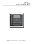
SXT Programming:
Programming
Abbreviation
Programming
Definition
* Option
Abbreviation
Option Definition
DF
Display Format
GAL
VT
Valve Type
DF 1b
CT
Control Type
tc
Time Clock – Regenerates based on days
NT
Number of Tanks
1
Single Tank
DO
Day Override
3
Days Between Regeneration – In
conditions of high water usage and/or
high levels of contaminants, the AIO may
need to regenerate more frequently than
once every three days. DO NOT set the
regeneration day override for a longer
period than three days, as the filter media
can become fouled with contaminates,
rendering the AIO ineffective.
RT
Regeneration
Time
12:30 AM
Regeneration Time – If there is a need to
change the factory default, then make
sure the time of regeneration is not the
same with any other water treatment
equipment in the system.
BW
Backwash
14
See AIO Overview Above
BD
Air Draw
40
See AIO Overview Above
RR
Rapid Rinse
4
See AIO Overview Above
BF
Brine Fill
Off
Gallons – 12 hour time
Downflow Single Backwash
Not Applicable
* Factory Defaults
Reference SXT service manual for programming information.
Page 1
2510 AIO Supplemental Insert
Installation Overview:
Install the AIO valve after the supply lines to the outside faucets (unless outside faucets need to be
free of contaminates in water). The AIO valve is generally installed before a water softener or any
taste/odor cartridges, if applicable.
Insure the inlet check valve is connected as shown to the inlet side of the AIO valve. The drain should
be installed in accordance with plumbing codes. Due to the release of air during regeneration, the
drain line should be anchored through out the run and secured at the end of the drain line. The drain
line should be sized for the backwash rate and friction loss.
The drain line flow control should accommodate the size tank and backwash rate for the filter
media being used.
The injector size (slow rinse rate based on pressure) should be sized the same as the service flow
rate of the filter media being used.
4
AIO Specific Parts:
Item# 1
2. 3. 3.
4.
5. 6. 7. Part # Description
*61662 PISTON ASSY, 2510AIO
*12777-01 CAM, AIR DRAW
*41861 CHECK VALVE, AIR DRAW
*13147-1.5 TUBE, DRAW, 1 1/2”, PVC
43154 SCREEN, AIR CHECK ADPTR
43152 CHECK VALVE, 2510AIO BRASS
43153 SCREW, 8-32, SS, 2510AIO
42188 KIT, PARTS, IRON FILTER
3
2
1
* Part not shown but illustration showing location
5
Drain
Deflector Installation:
Put a thin layer of silicone lube around inside diameter of
the deflector. Slowly slide the deflector over the distributor tube down about 1”. When threading the AIO valve to
the tank, the bottom of the threads will slide the deflector
down. As shown in diagram.
Reference the 2510 service manual for information on the following:
- Trouble shooting
- Parts list
P/N 42157
Rev. B
06/10
7
6