1
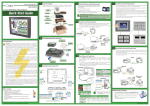
INSTALLATION & WIRING
CHAPTER
4
In This Chapter...
Safety Guidelines . . . . . . . . . . . . . . . . . . . . . . . . . . . . . . . . . . . . . . . . . . . . . . . . . . .4–2
Introduction . . . . . . . . . . . . . . . . . . . . . . . . . . . . . . . . . . . . . . . . . . . . . . . . . . . . . . .4–3
EA7-S6M-R, S6C-R, T6CL-R, S6M, S6C, T6C, T6CL – Cutout Dimensions . . . . . . . .4–4
EA7-T8C – Cutout Dimensions . . . . . . . . . . . . . . . . . . . . . . . . . . . . . . . . . . . . . . . . .4–5
EA7-T10C – Cutout Dimensions . . . . . . . . . . . . . . . . . . . . . . . . . . . . . . . . . . . . . . . .4–6
EA7-T12C – Cutout Dimensions . . . . . . . . . . . . . . . . . . . . . . . . . . . . . . . . . . . . . . . .4–7
EA7-T15C – Cutout Dimensions . . . . . . . . . . . . . . . . . . . . . . . . . . . . . . . . . . . . . . . .4–8
6” Adapter Plate – EA-6-ADPTR . . . . . . . . . . . . . . . . . . . . . . . . . . . . . . . . . . . . . . . .4–9
Mounting Clearances . . . . . . . . . . . . . . . . . . . . . . . . . . . . . . . . . . . . . . . . . . . . . . .4–11
Wiring Guidelines . . . . . . . . . . . . . . . . . . . . . . . . . . . . . . . . . . . . . . . . . . . . . . . . . .4–12
Agency Approvals . . . . . . . . . . . . . . . . . . . . . . . . . . . . . . . . . . . . . . . . . . . . . . . . .4–12
Marine Use . . . . . . . . . . . . . . . . . . . . . . . . . . . . . . . . . . . . . . . . . . . . . . . . . . . . . .4–12
Providing Power to the Touch Panel . . . . . . . . . . . . . . . . . . . . . . . . . . . . . . . . . . .4–13
DC Wiring Diagram . . . . . . . . . . . . . . . . . . . . . . . . . . . . . . . . . . . . . . . . . . . . . . . .4–13
AC Wiring Diagram (EA-AC) . . . . . . . . . . . . . . . . . . . . . . . . . . . . . . . . . . . . . . . . .4–14
Chapter 4: Installation and Wiring
1
2
3
4
5
6
7
8
9
10
11
12
13
14
A
B
C
D
Safety Guidelines
4–2
NOTE: Products with CE marks perform their required functions safely and adhere to relevant standards as
specified by CE directives provided they are used according to their intended purpose and that the
instructions in this manual are adhered to. The protection provided by the equipment may be impaired if this
equipment is used in a manner not specified in this manual. A listing of our international affiliates is available
on our Web site: http://www.automationdirect.com
WARNING: Providing a safe operating environment for personnel and equipment is your responsibility and
should be your primary goal during system planning and installation. Automation systems can fail and
may result in situations that can cause serious injury to personnel or damage to equipment. Do not rely
on the automation system alone to provide a safe operating environment. You should use external
electromechanical devices, such as relays or limit switches, that are independent of the PLC application
to provide protection for any part of the system that may cause personal injury or damage. Every
automation application is different, so there may be special requirements for your particular application.
Make sure you follow all national, state, and local government requirements for the proper installation
and use of your equipment.
Plan for Safety
The best way to provide a safe operating environment is to make personnel and equipment safety
part of the planning process. You should examine every aspect of the system to determine which areas
are critical to operator or machine safety. If you are not familiar with control system installation
practices, or your company does not have established installation guidelines, you should obtain
additional information from the following sources.
• NEMA — The National Electrical Manufacturers Association, located in Washington, D.C. publishes
many different documents that discuss standards for industrial control systems. You can order these
publications directly from NEMA. Some of these include:
ICS 1, General Standards for Industrial Control and Systems
ICS 3, Industrial Systems
ICS 6, Enclosures for Industrial Control Systems
• NEC — The National Electrical Code provides regulations concerning the installation and use of
various types of electrical equipment. Copies of the NEC Handbook can often be obtained from your
local electrical equipment distributor or your local library.
• Local and State Agencies — many local governments and state governments have additional
requirements above and beyond those described in the NEC Handbook. Check with your local
Electrical Inspector or Fire Marshall office for information.
®
EA-USER-M Hardware User Manual, 2nd Ed. Rev. G, 08/14
Chapter 4: Installation and Wiring
Introduction
The installation and wiring of the C-more® touch panels requires selecting an appropriate
location for the touch panel, laying out the cutout dimensions on the surface of the control
cabinet that the panel will be mounted through, securing the touch panel with the provided
mounting clips, tightening the screws to the appropriate torque rating to assure the gasket is
sealing correctly, and finally connecting the appropriate power source to the touch panel.
WARNING: C-more touch panels need to be mounted on a vertical surface to ensure proper cooling of the
panel and its components.
Note: Each C-more touch panel is provided with a cutout template to make marking the proper cutout size
on the surface of the control cabinet that the panel will be mounted through a simple task.
The C-more 6” touch panels include two mounting clips. The clips can be viewed as a long
metal bracket with two screws in each clip. The 6” panel clips can be fitted to the touch panel
at two different depth locations that allow the 6” panel to be mounted through a wide range of
enclosure thicknesses. The 8” through 12” touch panels include six mounting clips while the
15” touch panel includes eight. The 8” through 15” panel mounting clips are all the same. They
are fitted to the touch panel by inserting two tabs into mating wide slots around th panel and
then sliding the clip into a narrower slot to secure it in place. There is one screw on each clip
that needs tightening to secure the panel in place.
Any C-more touch panel can be mounted directly through the existing cutout of a same size
EZTouch slim touch panel. There is a simple solution for the need to replace an EZTouch 6”
non-slim (rounded bezel) touch panel as explained in the following note.
NOTE: The C-more 6” touch panels will fit into the existing cutout of any EZTouch 6” slim bezel panel. Use
the C-more 6” Adapter Plate, EA-6-ADPTR, to install C-more 6” panels into existing cutouts of EZTouch 6”
non-slim (rounded bezel) panels. The adapter plate gasket is included.
This chapter only covers the proper mounting of the touch panel and connecting power. Once
power is applied to the touch panel, the user will want to read Chapter 5 on the System Setup
Screens in order to set the internal time and date for the panel, check the information menu to
make sure the panel is the correct unit for the application and is the latest version, set
communication port parameters that may be required, become familiar with the touch panel
test features, and check memory options.
The next step will be to select the appropriate PLC protocol and communications cable as
described in Chapter 6.
6” Mounting Clips
®
8-15” Mounting Clip
EA-USER-M Hardware User Manual, 2nd Ed. Rev. G, 08/14
1
2
3
4
5
6
7
8
9
10
11
12
13
14
A
B
C
D
4–3
Chapter 4: Installation and Wiring
EA7-S6M-R, S6C-R, T6CL-R, S6M, S6C, T6C, T6CL –
1 Cutout Dimensions
2
3
4
5
6
7
8
9
10
11
12
13
14
A
B
C
D
4–4
The C-more 6” touch panels are mounted into a cutout through the control cabinet and secured
with two (2) mounting clips. The mounting clips are provided with the touch panel. There is a
set of four (4) rectangular holes (slots) on each side of the touch panel’s short dimension that
the two tabs on each mounting clip will match. You will need to select either the upper or lower
set of holes depending on your control cabinet’s material thickness. The table below shows the
different thickness ranges. The mounting clips are held in place, and pull the front bezel of the
panel tight to the mounting surface, by tightening the screws into the rear of the control
cabinet. The screws need to be tightened to the torque rating shown in the table below so that
the gasket is compressed to form the proper seal between the panel and cabinet surface.
Note: Mount the touch panel on a vertical surface to allow convection air flow for proper cooling.
Mounting Clip
(2) places
7.460 +0.04
-0.0
[189.5 +1.0
-0.0]
0.630
[16.0]
0.315
[8.0]
0.294
[7.5]
0.294
[7.5]
5.512 +0.04
-0.0
[140.0 +1.0
-0.0]
CUTOUT
Bezel Outline
0.315
[8.0]
Cutout Outline
Units: inches[mm]
0.630
[16.0]
0.709
[18.0]
6.533
[165.9]
0.709
[18.0]
Enclosure Mounting Thickness Ranges
and Mounting Clip Screw Torque
Mounting Clip
Screw Torque
Enclosure Mounting
Thickness Range
®
Touch
Panel Size
Enclosure
Thickness Range
Mounting Clip
Screw Torque
6” – lower mounting
clip position
6” – upper mounting
clip position
0.039 - 0.24 inch
[1 – 6 mm]
35 ~ 50 oz-in
[0.25 ~ 0.35 Nm]
0.20 - 0.63 inch
[5 – 16 mm]
35 ~ 50 oz-in
[0.25 ~ 0.35 Nm]
EA-USER-M Hardware User Manual, 2nd Ed. Rev. G, 08/14
Chapter 4: Installation and Wiring
EA7-T8C – Cutout Dimensions
The C-more 8” touch panels are mounted into a cutout through the control cabinet and secured
with six (6) mounting clips. The mounting clips are provided with the touch panel. The
mounting clips will insert into a series of slots around the rear perimeter of the touch panel.
Each clip has two tabs that will mate to two slots, using the larger rectangular holes. The
mounting clips are held in place by sliding the clip toward the smaller rectangular holes. The
screw of each mounting clip needs to be tightened to the torque rating shown in the table below
so that the gasket is compressed to form the proper seal between the panel and cabinet surface.
Note: Mount the touch panel on a vertical surface to allow convection air flow for proper cooling.
9.250 +0.04
-0.0
[235.0 +1.0
-0.0]
0.394
[10.0]
0.822
[20.9]
0.394
[10.0]
4.625
[117.5]
Mounting Clip
(6) places
0.394
[10.0]
0.822
[20.9]
0.837
[21.3]
CUTOUT
7.075 +0.04
-0.0
[179.7 +1.0
-0.0 ]
Cutout Outline
3.537
[89.9]
Units: inches [mm]
Bezel Outline
0.837 0.394
[21.3] [10.0]
Enclosure Mounting Thickness Ranges
and Mounting Clip Screw Torque
Mounting Clip
Screw Torque
Enclosure Mounting
Thickness Range
®
Touch
Panel Size
Enclosure
Thickness Range
Mounting Clip
Screw Torque
8”, 10”, 12” & 15”
0.039 - 0.20 inch
[1 – 5 mm]
42 ~ 57 oz-in
[0.3 ~ 0.4 Nm]
EA-USER-M Hardware User Manual, 2nd Ed. Rev. G, 08/14
1
2
3
4
5
6
7
8
9
10
11
12
13
14
A
B
C
D
4–5
Chapter 4: Installation and Wiring
1
2
3
4
5
6
7
8
9
10
11
12
13
14
A
B
C
D
EA7-T10C – Cutout Dimensions
The C-more 10” touch panels are mounted into a cutout through the control cabinet and
secured with six (6) mounting clips. The mounting clips are provided with the touch panel. The
mounting clips will insert into a series of slots around the rear perimeter of the touch panel.
Each clip has two tabs that will mate to two slots, using the larger rectangular holes. The
mounting clips are held in place by sliding the clip toward the smaller rectangular holes. The
screw of each mounting clip needs to be tightened to the torque rating shown in the table below
so that the gasket is compressed to form the proper seal between the panel and cabinet surface.
Note: Mount the touch panel on a vertical surface to allow convection air flow for proper cooling.
11.908 +0.04
-0.0
[302.5 +1.0
-0.0]
0.394
[10.0]
0.394
[10.0]
5.954
[151.2]
0.877
[22.3]
0.877
[22.3]
0.876
[22.3]
Mounting Clip
(6) places
0.394
[10.0]
CUTOUT
8.917 +0.04
-0.0
[226.5 +1.0
-0.0 ]
Cutout Outline
Units: inches [mm]
4.459
[113.2]
Bezel Outline
4–6
0.876
[22.3]
0.394
[10.0]
Enclosure Mounting Thickness Ranges
and Mounting Clip Screw Torque
Mounting Clip
Screw Torque
Enclosure Mounting
Thickness Range
®
Touch
Panel Size
Enclosure
Thickness Range
Mounting Clip
Screw Torque
8”, 10”, 12” & 15”
0.039 - 0.20 inch
[1 – 5 mm]
42 ~ 57 oz-in
[0.3 ~ 0.4 Nm]
EA-USER-M Hardware User Manual, 2nd Ed. Rev. G, 08/14
Chapter 4: Installation and Wiring
EA7-T12C – Cutout Dimensions
The C-more 12” touch panels are mounted into a cutout through the control cabinet and
secured with six (6) mounting clips. The mounting clips are provided with the touch panel. The
mounting clips will insert into a series of slots around the rear perimeter of the touch panel.
Each clip has two tabs that will mate to two slots, using the larger rectangular holes. The
mounting clips are held in place by sliding the clip toward the smaller rectangular holes. The
screw of each mounting clip needs to be tightened to the torque rating shown in the table below
so that the gasket is compressed to form the proper seal between the panel and cabinet surface.
Note: Mount the touch panel on a vertical surface to allow convection air flow for proper cooling.
12.579 +0.04
-0.0
[319.5 +1.0
-0.0 ]
0.354
[9.0]
0.354
[9.0]
6.289
[159.7]
0.394
[10.0]
Mounting Clip
(6) places
0.394
[10.0]
CUTOUT
0.354
[9.0]
0.394
[10.0]
10.236 +0.04
-0.0
[260.0 +1.0
-0.0 ]
5.118
[130.0]
Units: inches [mm]
Cutout Outline
Bezel Outline
0.394
[10.0]
0.354
[9.0]
Enclosure Mounting Thickness Ranges
and Mounting Clip Screw Torque
Mounting Clip
Screw Torque
Enclosure Mounting
Thickness Range
®
Touch
Panel Size
Enclosure
Thickness Range
Mounting Clip
Screw Torque
8”, 10”, 12” & 15”
0.039 - 0.20 inch
[1 – 5 mm]
42 ~ 57 oz-in
[0.3 ~ 0.4 Nm]
EA-USER-M Hardware User Manual, 2nd Ed. Rev. G, 08/14
1
2
3
4
5
6
7
8
9
10
11
12
13
14
A
B
C
D
4–7
Chapter 4: Installation and Wiring
1
2
3
4
5
6
7
8
9
10
11
12
13
14
A
B
C
D
EA7-T15C – Cutout Dimensions
The C-more 15” touch panels are mounted into a cutout through the control cabinet and
secured with eight (8) mounting clips. The mounting clips are provided with the touch panel.
The mounting clips will insert into a series of slots around the rear perimeter of the touch panel.
Each clip has two tabs that will mate to two slots, using the larger rectangular holes. The
mounting clips are held in place by sliding the clip toward the smaller rectangular holes. The
screw of each mounting clip needs to be tightened to the torque rating shown in the table below
so that the gasket is compressed to form the proper seal between the panel and cabinet surface.
Note: Mount the touch panel on a vertical surface to allow convection air flow for proper cooling.
0.395
[10.0]
14.960 +0.04
-0.0
[380.0 +1.0
-0.0 ]
0.395
[10.0]
7.480
[190.0]
0.894
[22.7]
0.894
[22.7]
Mounting Clip
(8) places
0.406
[10.3]
0.864
[21.9]
CUTOUT
11.276 +0.04
-0.0
[286.4 +1.0
-0.0 ]
Cutout Outline
5.638
[143.2]
Units: inches[mm]
Bezel Outline
4–8
0.864
[21.9]
0.406
[10.3]
Enclosure Mounting Thickness Ranges
and Mounting Clip Screw Torque
Mounting Clip
Screw Torque
Enclosure Mounting
Thickness Range
®
Touch
Panel Size
Enclosure
Thickness Range
Mounting Clip
Screw Torque
8”, 10”, 12” & 15”
0.039 - 0.20 inch
[1 – 5 mm]
42 ~ 57 oz-in
[0.3 ~ 0.4 Nm]
EA-USER-M Hardware User Manual, 2nd Ed. Rev. G, 08/14
Chapter 4: Installation and Wiring
6” Adapter Plate
Use the C-more 6” Adapter Plate, p/n EA-6-ADPTR,
to install a C-more 6” touch panel into the existing
cutout of an EZTouch 6” non-slim (rounded bezel)
touch panel. Gasket and mounting hardware is
included.
Part No. EA-6-ADPTR
6” Adapter Plate Assembly
6“ C-more
Touch Panel
C-more
Adapter Plate
Enclosure
Two sets of mounting screws provided:
Set A - M4-8 metric screws for an enclosure
thickness range of 0.02-0.118 inch [0.5-3mm]
Set B - M4-10 metric screws for an enclosure
thickness range of 0.118-0.197 inch [3-5mm]
Mounting screw torque: 100 oz-in [0.7 Nm]
DIN Mounting
Clips
Screw Torque: 100 oz-in [0.7 Nm]
®
EA-USER-M Hardware User Manual, 2nd Ed. Rev. G, 08/14
1
2
3
4
5
6
7
8
9
10
11
12
13
14
A
B
C
D
4–9
Chapter 4: Installation and Wiring
1
2
3
4
5
6
7
8
9
10
11
12
13
14
A
B
C
D
6” Adapter Plate (cont’d)
6” Adapter Plate Dimensions
8.932
[226.9]
0.618
[15.7]
0.118 ±0.04
[3.0 ±1.0]
7.299
[185.4]
4–10
M4
Thread
Insert
(6 places)
Units: inches[mm]
Adapter
Front View
8.076 ±0.02
[205.1 ±0.5]
4.250 ±0.02
[108.0 ±0.5]
6.223 ±0.02
[158.1 ±0.5]
Centerline
Gasket
Side View
Rear View
6” Adapter Plate Cutout Dimensions
8.076
[205.1]
4.250
[108.0]
Adapter Plate
Outline
0.837
[21.3]
2.125
[54.0]
Centerline
0.218 Dia.
[5.5]
(6 places)
CUTOUT
6.222
[158.0]
5.624
[142.8]
3.111
[79.0]
Units: inches [mm]
2.812
[71.4]
3.761
[95.5]
0.705
[17.9]
®
0.837
[21.3]
7.522
[191.1]
0.705
[17.9]
EA-USER-M Hardware User Manual, 2nd Ed. Rev. G, 08/14
Chapter 4: Installation and Wiring
Mounting Clearances
The following drawing shows the mounting clearances for the C-more touch panel. There
should be a minimum of 4 inches of space between all sides of the panel and the nearest object
or obstruction and at least 2 inches between the rear of the panel and the nearest object or
obstruction.
Note: Make sure the touch panel is mounted on a vertical surface to allow convection air flow for proper
cooling.
Mounting Clip
4“ Min.
2“ Min.
4“ Min.
4“ Min.
4“ Min.
Front View
®
Air
Flow
Side View
EA-USER-M Hardware User Manual, 2nd Ed. Rev. G, 08/14
1
2
3
4
5
6
7
8
9
10
11
12
13
14
A
B
C
D
4–11
Chapter 4: Installation and Wiring
1
2
3
4
5
6
7
8
9
10
11
12
13
14
A
B
C
D
Wiring Guidelines
4–12
WARNING: To minimize the risk of potential safety problems, you should follow all applicable local and
national codes that regulate the installation and operation of your equipment. These codes vary from
area to area and it is your responsibility to determine which codes should be followed, and to verify
that the equipment, installation, and operation are in compliance with the latest revision of these
codes.
Equipment damage or serious injury to personnel can result from the failure to follow all applicable
codes and standards. We do not guarantee the products described in this publication are suitable for
your particular application, nor do we assume any responsibility for your product design, installation,
or operation.
If you have any questions concerning the installation or operation of this equipment, or if you need
additional information, please call us at 1-800-633-0405 or 770-844-4200.
This publication is based on information that was available at the time it was printed. At
Automationdirect.com® we constantly strive to improve our products and services, so we reserve the
right to make changes to the products and/or publications at any time without notice and without
obligation. This publication may also discuss features that may not be available in certain revisions of
the product.
Agency Approvals
Some applications require agency approvals for particular components. The C-more touch panel
agency approvals are listed below:
• UL (Underwriters’ Laboratories, Inc.)
• CUL (Canadian Underwriters’ Laboratories, Inc.)
• CSA (Canadian Standards Association)
• CE (European Economic Union)
Marine Use
American Bureau of Shipping (ABS) certification requires flame-retarding insulation as per 48-3/5.3.6(a). ABS will accept Navy low smoke cables, cable qualified to NEC “Plenum rated”
(fire resistant level 4), or other similar flammability resistant rated cables. Use cable
specifications for your system that meet a recognized flame retardant standard (i.e. UL, IEEE,
etc.), including evidence of cable test certification (i.e. tests certificate, UL file number, etc.).
NOTE: Wiring needs to be “low smoke” per the above paragraph. Teflon coated wire is also recommended.
®
EA-USER-M Hardware User Manual, 2nd Ed. Rev. G, 08/14
Chapter 4: Installation and Wiring
Wiring Guidelines (cont’d)
Providing Power to the Touch Panel
• Connect a dedicated 24 VDC (20.4 - 28.8 VDC) switching power supply rated for a minimum of
1.5 A to the DC connector on the rear of the C-more touch panel. Connect the ground terminal to
a proper equipment ground.
• or install a C-more AC/DC Power Adapter (EA-AC) to the rear of the touch panel and connect an
AC voltage source of 100-240 VAC, 50/60Hertz, to its AC connector.
• then turn on the power source and check the LED status indicators on the rear of the C-more touch
panel for proper operation. See the LED Status Indicator diagram on the next page for reference.
DC Wiring Diagram
DC Wiring
Recommended DC Supply Fuse
Panel Size Rating
6“ – 10”
2.5 A
12“ & 15”
4.0 A
ADC p/n
MDL2-5
MDL4
+
24 VDC, -15%, +20%
(20.4 - 28.8 VDC)
–
GND
PWR
CPU
Equipment
Ground
BATT
Recommended DC Power Supply:
AutomationDirect Part No. PS24-050D
®
EA-USER-M Hardware User Manual, 2nd Ed. Rev. G, 08/14
1
2
3
4
5
6
7
8
9
10
11
12
13
14
A
B
C
D
4–13
Chapter 4: Installation and Wiring
1
2
3
4
5
6
7
8
9
10
11
12
13
14
A
B
C
D
Wiring Guidelines (cont’d)
4–14
AC Wiring Diagram
AC Wiring
AC Power Adapter
Not recommended for use with the EA7-T15C
when operating temperatures are expected
to be above 40 deg C.
AC/DC Power Adapter
EA-AC
Recommended AC Supply Fuse
3.0 A time delay, ADC p/n MDL3
100 - 240 VAC
50/60 Hz
WARNING: The AC/DC Power Adapter is not recommended for use with the EA7-T15C touch panel when
operating temperatures are expected to exceed 40 °C [104 °F].
Note: Power Fault features help protect data being logged to CompactFlash during power failures. The
C-more panel must have firmware version 1.21 Build 6.18E or higher for proper operation.
C-more LED Status Indicators
Power LED (Green)
CPU Status LED (Green, Orange & Red)
Off
Green
Red
Blinking
Red
Blinking
Orange
Blinking
Green
Power Off
PWR
Normal – CPU Run State
Memory Error
Operating System not found
LCD Backlight Failure
Power Loss Detection
®
On
Power On
Off
Power Off
CPU
TxD
RxD
BATT
Serial TxD/RxD LED (Green)
IOlOl–PLC
Rear View
On Comm. is active
Off No communication
EA-USER-M Hardware User Manual, 2nd Ed. Rev. G, 08/14