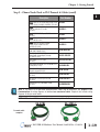
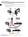
1
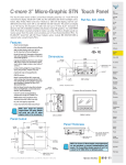
GETTING STARTED
CHAPTER
1
In This Chapter...
Introduction . . . . . . . . . . . . . . . . . . . . . . . . . . . . . . . . . . . . . . . . . . . . . . . . . . . . . . .1–2
Conventions Used . . . . . . . . . . . . . . . . . . . . . . . . . . . . . . . . . . . . . . . . . . . . . . . . . . .1–3
Mounting Clips – New Style . . . . . . . . . . . . . . . . . . . . . . . . . . . . . . . . . . . . . . . . . . .1–3
Product Overview . . . . . . . . . . . . . . . . . . . . . . . . . . . . . . . . . . . . . . . . . . . . . . . . . . .1–4
Part Number Key – Touch Panels . . . . . . . . . . . . . . . . . . . . . . . . . . . . . . . . . . . . . . .1–5
EZTouch Conversion and Mounting . . . . . . . . . . . . . . . . . . . . . . . . . . . . . . . . . . . . .1–6
EZTouch Touch Panel Cross Reference to C-more . . . . . . . . . . . . . . . . . . . . . . . . . .1–7
Quick Start Steps . . . . . . . . . . . . . . . . . . . . . . . . . . . . . . . . . . . . . . . . . . . . . . . . . . . .1–9
Step 1 – Unpack and Inspect . . . . . . . . . . . . . . . . . . . . . . . . . . . . . . . . . . . . . . . . . .1–9
Step 2 – Assemble Temporary Support Stand . . . . . . . . . . . . . . . . . . . . . . . . . . . .1–10
Step 3 – Install Optional Hardware Accessories . . . . . . . . . . . . . . . . . . . . . . . . . . .1–11
Step 4 – Become Familiar with Available Communication Ports . . . . . . . . . . . . . . .1–12
Step 5 – Install the Programming Software and Develop a Project . . . . . . . . . . . .1–13
Step 6 – Connect Touch Panel to Computer . . . . . . . . . . . . . . . . . . . . . . . . . . . . .1–14
Step 7 – Provide Power to the Touch Panel . . . . . . . . . . . . . . . . . . . . . . . . . . . . . .1–15
Step 8 – Access the Touch Panel Setup Screens . . . . . . . . . . . . . . . . . . . . . . . . . . .1–16
Step 9 – Choose Touch Panel to PLC Protocol & Cables . . . . . . . . . . . . . . . . . . . .1–17
Step 10 – Connect Touch Panel to PLC . . . . . . . . . . . . . . . . . . . . . . . . . . . . . . . . .1–20
Chapter 1: Getting Started
1
2
3
4
5
6
7
8
9
10
11
12
13
14
A
B
C
D
Introduction
1–2
The Purpose of this Manual
Thank you for purchasing our C-more® Touch Panel family of products. This manual describes
AutomationDirect.com’s C-more Touch Panels, their specifications, included components,
available accessories and provides you with important information for installation, connectivity
and setup. The manual shows you how install, wire and use the products. It also helps you
understand how to interface the panels to other devices in a control system.
This user manual contains important information for personnel who will install the touch
panels and accessories, and for the personnel who will be programming the panel. If you
understand control systems that make use of operating interfaces such as the C-more touch
panels, our user manuals will provide all the information you need to get, and keep your system
up and running.
Supplemental Manuals
If you are familiar with industrial control type devices, you may be able to get up and running
with just the aide of the Quick Start Guide that is included with each touch panel. You can also
refer to the On-line help that is available in the C-more programming software for more
information about programming the panel. The accessories include data sheets that will help
with installing the accessories.
Technical Support
We strive to make our manuals the best in the industry. We rely on your feedback to let us know
if we are reaching our goal. If you cannot find the solution to your particular application, or, if
for any reason you need technical assistance, please call us at:
770–844–4200
Our technical support group will work with you to answer your questions. They are available
Monday through Friday from 9:00 A.M. to 6:00 P.M. Eastern Time. We also encourage you to
visit our web site where you can find technical and non-technical information about our
products and our company.
http://cmore.automationdirect.com
If you have a comment, question or suggestion about any of our products, services, or manuals,
please fill out and return the ‘Suggestions’ card that was included with this manual.
®
EA-USER-M Hardware User Manual, 2nd Ed. Rev. G, 08/14
Chapter 1: Getting Started
Conventions Used
When you see the “notepad” icon in the left-hand margin, the paragraph to its immediate right will be a
special note. The word NOTE: in boldface will mark the beginning of the text.
When you see the “exclamation mark” icon in the left-hand margin, the paragraph to its immediate right
will be a warning. This information could prevent injury, loss of property, or even death (in extreme
cases). The word WARNING: in boldface will mark the beginning of the text.
Key Topics for Each Chapter
The beginning of each chapter will list the key topics
that can be found in that chapter.
Getting Started
1
CHAPTER
In This Chapter...
General Information .................................................................1-2
Specifications ...........................................................................1-4
Mounting Clips – New Style
NOTE: C-more touch panels shipped prior to approximately April 2006 had a slightly different mounting clip
design. All of the drawings and illustrations in this issue of the Hardware User Manual are shown with the
newer design. Appendix C: Mounting Clips Prior April 2006 contains drawings and illustrations of the
original designed mounting clips for your reference.
®
EA-USER-M Hardware User Manual, 2nd Ed. Rev. G, 08/14
1
2
3
4
5
6
7
8
9
10
11
12
13
14
A
B
C
D
1–3
Chapter 1: Getting Started
1
2
3
4
5
6
7
8
9
10
11
12
13
14
A
B
C
D
Product Overview
1–4
Some of the features designed into the product to provide excellent hardware and software are
listed below.
• Analog touch screen (no touch cell boundaries). The touchscreen is designed to respond to a single
touch. If it is touched at multiple points at the same time, an unexpected object may be activated.
• Plenty of memory and methods to get data in/out of the panel
• Overlapping active devices on the touch screen
• 65,536 colors for enhanced graphics
• Screen resolutions up to 1024 X 768 pixels
• Built-in project simulation; test on PC while developing
• Serial RS232, RS422/485 and Ethernet 10/100Base-T communications
(Ethernet available on full feature units only.)
• Programming via USB or Ethernet (Ethernet available on full feature units only.)
• Optional AC/DC power adapter (EA-AC)
• Bright backlight bulbs
• Animation of bitmaps and objects
• 4,000 built-in symbols, classic fonts: 6x8, 8x16, 8x32, 8x64, 16x16, 16x32, 16x64,
32x16, 32x32, 32x64, and Windows fonts
• PID face plate, trending, alarming and a recipe database
• Event Manager to trigger actions based on assigned state changes, schedules, PLC tag names, etc.
setup in a database environment. The event can also trigger a sound byte, initiate a screen capture,
send a data file (FTP), send an E-mail, etc.
• Select unique background screens for each created screen
• Trend Data logging
• Internet Remote Access
• Built-in FTP client/server, E-mail client, and Web server
• Audio output port - stereo, requires amplifier and speaker(s)
®
EA-USER-M Hardware User Manual, 2nd Ed. Rev. G, 08/14
Chapter 1: Getting Started
Part Number Key – Touch Panels
The C-more touch panel part numbers consist of the following key:
Screen Size:
6: 5.7”
8: 8.4”
10: 10.4”
12: 12.1”
15: 15.0”
Features:
L: LED
LCD Type:
S: STN
T: TFT
Color:
C: Color
M: Grayscale
EA7-xxxx-x
Features:
blank: Full
R: Base
Product label examples:
EA7-T6CL-R
EA7-T15C
Serial Number and Date Code formats:
Serial Number =
YY:
M:
DD:
F:
NNN:
[Part Number]+[YYMDDFNNN]
Year (05–99 --- e.g. 05 = 2005)
Month (1–9, X, Y, Z --- e.g. X = Oct.)
Day (1–31)
Manufacturing Site (0–9, A–Z)
Sequence number for the date listed (000–999)
YMMF
Date Code =
Y:
MM:
F:
Year (0–9 --- e.g. 07 = 2007)
Month (01–12 --- e.g. X = Oct.)
Manufacturing Site (0–9, A–Z)
®
EA-USER-M Hardware User Manual, 2nd Ed. Rev. G, 08/14
1
2
3
4
5
6
7
8
9
10
11
12
13
14
A
B
C
D
1–5
Chapter 1: Getting Started
1
2
3
4
5
6
7
8
9
10
11
12
13
14
A
B
C
D
EZTouch Conversion and Mounting
1–6
C-more panels are a drop-in replacement for EZTouch panels from AutomationDirect. They fit
the same panel cutout*. The C-more software will convert your legacy EZTouch project (created
with EZTouch Edit ver. 3.1a) automatically with no changes to the project required.** Just open
your old EZTouch project in the new C-more Programming Software, connect the USB cable,
and click "Send to Panel". The conversion is automatic and you will benefit immediately from:
• A better looking display
• A brighter screen
• Longer backlight bulb life
• Wider temperature tolerance
• A two year warranty
Note: EZTouch projects most have been created with EZTouch Edit software version 3.1a to assure proper
project conversion.
Now, there are hundreds of new features you may want to take advantage of, but it's nice to
know that you can be up and running your existing EZTouch project in just a few minutes.
C-more accepts the same PLC communications and networking cables that you are using with
EZTouch. The 24 VDC power connections accept the same DC wiring that you used for
EZTouch, and now there is a removable terminal block connector. Only the programming cable
is different - you no longer have to buy a proprietary serial cable to program your touch panel.
C-more uses a standard USB cable or an Ethernet (CAT5) connection for programming.
* If you have an old 6" non-slim bezel EZTouch panel you will need our 6" Adapter Plate, part number
EA-6-ADPTR, see the chapter on accessories.
** The project conversion utility is a great feature. However the user must take full responsibility in
ensuring the conversion works to their satisfaction.
Example of a C-more 6” touch panel
mounted into an existing EZTouch
non-slim bezel cutout using the
C-more 6” adapter plate.
®
EA-USER-M Hardware User Manual, 2nd Ed. Rev. G, 08/14
Chapter 1: Getting Started
EZTouch Touch Panel Cross Reference to C-more
EZTouch
EZTouch 6”, grayscale STN
(0–45 °C)
EZ-S6M-R
C-more*
C-more 6” Adapter
Requires:
EA-6-ADPTR
Requires:
EA-6-ADPTR
C-more 6”, grayscale STN
(0–50 °C)
EA7-S6M-R
EZ-S6M-RS
EZ-S6M-F
EZ-S6M-FS
EZTouch
EZTouch 6”, 128 Color STN
(0–45 °C)
EZ-S6C-K
Requires:
EA7-S6M
(includes Ethernet)
C-more*
C-more 6” Adapter
C-more 6”, 65,536 Color TFT
(0–50 °C)
EA-6-ADPTR
EA7-T6CL-R
EZ-S6C-KS
EZ-S6C-F
Requires:
EA-6-ADPTR
EA7-T6CL
(includes Ethernet)
EZ-S6C-FS
EZ-S6C-FST
EZTouch
C-more*
EZTouch 8”, 128 Color STN
(0–40 °C)
C-more 8”, 65,536 Color TFT
(0–50 °C)
EZ-S8C-F
EA7-T8C
(includes Ethernet)
EZ-S8C-FS
EZ-S8C-FST
*Note: All C-more touch panels meet UL type 4X when mounted on a flat surface of a type 4X indoor use
only enclosure. Non-FDA
®
EA-USER-M Hardware User Manual, 2nd Ed. Rev. G, 08/14
1
2
3
4
5
6
7
8
9
10
11
12
13
14
A
B
C
D
1–7
Chapter 1: Getting Started
1
2
3
4
5
6
7
8
9
10
11
12
13
14
A
B
C
D
EZTouch Touch Panel Cross Reference to C-more (cont’d)
EZTouch
C-more*
EZTouch 10”, 128 Color TFT
(0–50 °C)
C-more 10”, 65,536 Color TFT
(0–50 °C)
EZ-S10C-F
EZ-T10C-FS
EA7-T10C
(includes Ethernet)
EZ-T10C-FST
EZ-T10C-FSE
EZTouch
C-more*
No 12” EZTouch available
C-more 12”, 65,536 Color TFT
(0–50 °C)
EA7-T12C
(includes Ethernet)
EZTouch
C-more*
EZTouch 15”, 128 Color TFT
(0–45 °C)
C-more 15”, 65,536 Color TFT
(0–50 °C)
EZ-T15C-FS
EA7-T15C
(includes Ethernet)
EZ-T15C-FST
EZ-T15C-FSE
1–8
*Note: All C-more touch panels meet UL type 4X when mounted on a flat surface of a type 4X indoor use
only enclosure. Non-FDA
®
EA-USER-M Hardware User Manual, 2nd Ed. Rev. G, 08/14
Chapter 1: Getting Started
Quick Start Steps
Step 1 – Unpack and Inspect
a.) Unpack the C-more Touch Panel from its shipping carton. Included in the carton are the
following:
• C-more Touch Panel
• cutout template
• mounting clips
• temporary support stand
• DC power connector
• gasket
• Quick Start Guide, p/n EA-QSG
b.) Unpack any accessories that have been
ordered, such as: AC/DC Power
Adapter, Expansion Assembly,
CompactFlash memory, programming
cable, communications cable, etc.
c.) Inspect all equipment for
completeness. If anything is missing
or damaged, immediately call the
AutomationDirect® returns
department @ 1-800-633-0405.
Temporary
Support Stand
Cutout Template
located here.
Mounting Clips
and DC power connector
located in here.
Shipping Carton Contents
Optional Accessories
AC Power Adapter
EA-AC
®
Expansion Assembly
EA-EXP-OPT
Compact Flash Card
EA-CF-CARD
EA-USER-M Hardware User Manual, 2nd Ed. Rev. G, 08/14
1
2
3
4
5
6
7
8
9
10
11
12
13
14
A
B
C
D
1–9
Chapter 1: Getting Started
Step 2 – Assemble Temporary Support Stand
1
2
3
4
5
6
7
8
9
10
11
12
13
14
A
B
C
D
6“ & 8” Touch Panel – Temporary Stand
2
1
3
4
Shipping Carton Packing Material
6
5
7
8
10”, 12“ & 15” Touch Panel – Temporary Stand
1–10
1
2
3
Shipping Carton Packing Material
Insert tabs
between layers
4
5
6
NOTE: See Chapter 4: Installation and Wiring for C-more touch panel installtion information including
cutout dimensions and mounting clearances.
®
EA-USER-M Hardware User Manual, 2nd Ed. Rev. G, 08/14
Chapter 1: Getting Started
Step 3 – Install Optional Hardware Accessories
NOTE: CompactFlash memory card designations – CF Slot #1 is at the top of the panel and CF Slot #2 is the
CF Card Interface Module, p/n EA-CF-IF.
CF Card
Interface Module
EA-CF-IF
Compact Flash Memory Card
EA-CF-CARD
CF card interface
module installs
in right slot only,
left slot for future
CF card plugs
into slot #1
at top of panel
Expansion Assembly
EA-EXP-OPT
C-more
Touch Panel
AC/DC Power Adapter
EA-AC
NOTE: The C-more 6” touch panels will fit into the existing cutout of any EZTouch 6” slim bezel panel. Use
the C-more 6” Adapter Plate, p/n EA-6-ADPTR, to install C-more 6” panels into existing cutouts of EZTouch
6” non-slim (rounded bezel) panels.
Optional Accessories
6” Adapter Plate
EA-6-ADPTR
15-pin Terminal
Block Adapter
EA-COMCON-3
Date code
15-pin 90 Degree
Comm. Port Adapter
EA-ADPTR-4
Date code
Country of Origin
Country of Origin
®
KOYO ELECTRONICS INDUSTRIES CO., LTD.
TERM
RD+
RD–
SD+
EA-COMCON-3
SD–
GND
KOYO ELECTRONICS INDUSTRIES CO., LTD.
EA-ADPTR-4
IOIOI – PLC
EA-USER-M Hardware User Manual, 2nd Ed. Rev. G, 08/14
1
2
3
4
5
6
7
8
9
10
11
12
13
14
A
B
C
D
1–11
Chapter 1: Getting Started
Step 4 – Become Familiar with Available Communication Ports
1
2
3
4
5
6
7
8
9
10
11
12
13
14
A
B
C
D
Compact Flash
memory slot #1
is located at the
top of panel.
PLC Serial Communications
8
1
15
9
Pin
Signal
Pin
1
Frame GND
6
LE
11
2
TXD (232C)
7
CTS (232C)
12 TXD– (422/485)
3
RXD (232C)
8
RTS (232C)
13 Term. Resistor
4
Future
9
RXD+ (422/485)
14 do not use
5
Logic GND
10 RXD– (422/485)
15 do not use
Pin
USB Port - Type B
Programming/Download
1–12
USB Port - Type A
USB Device Options
Signal
Vbus
2
D–
3
D+
4
GND
Signal
TXD+ (422/485)
Ethernet 10/100 Base-T
PLC Communications,
Programming/Download
Audio Line Out,
stereo, 1 Volt rms,
3.5mm Mini Jack
(Amplifier Required)
1
Pin
Bottom View
For Future Use
Pin
Signal
Pin
2
1
3
4
1 2 3 4
Shell Shield
1
Signal
Signal
Pin
Signal
1
TD+
5
do not use
2
TD–
6
RD–
3
RD+
7
do not use
4
do not use
8
Vbus
1
do not use
8
2
D–
Link Status LED (Green)
3
D+
On
Ethernet Linked
Network Activity LED (Orange)
On
Active Network Data
4
GND
Off
No Ethernet Comm.
Off
Network Idle
SHELL Shield
Note: Device is not available on Base Feature touch panels, part numbers EA7-S6M-R and EA7-T6CL-R.
Note: Use USB Programming Cable, for example p/n USB-CBL-AB15.
Note: See Chapter 2: Specifications and Chapter 6: PLC Communications for additional details on the
available communication ports, protocols and cables.
®
EA-USER-M Hardware User Manual, 2nd Ed. Rev. G, 08/14
Chapter 1: Getting Started
Step 5 – Install the Programming Software and Develop a Project
Following are the minimum system requirements for running C-more Programming Software,
p/n EA-PGMSW, on a PC:
• Personal Computer with a 333 MHz or higher processor (CPU) clock speed recommended;
Intel® Pentium/Celeron family, or AMD® K6/Athlon/Duron family, or compatible processor
recommended
• Keyboard and Mouse or compatible pointing device
• Super VGA color video adapter and monitor with at least 800 x 600 pixels resolution
(1024 x 768 pixels recommended)
64K color minimum
• 300 MB free hard-disk space
• 128 MB free RAM (512 MB recommended); 512 MB free RAM (1 GB recommended) for
Vista
• CD-ROM or DVD drive for installing software from the CD
• USB port or Ethernet 10/100 Mbps port for project transfer from software to touch panel
(Ethernet port not available on -R models)
• Operating System - Windows® XP Home / Professional Edition Service Pack 2 (32 bit) ,
Windows 2000 with Service Pack 4, Windows Vista® (32 or 64 bit) or Windows 7 (32 or 64
bit), Windows 8
Insert the supplied CD-ROM into the PC’s CD-ROM drive and follow
the instructions. If you need assistance during the software installation,
please refer to the supplied Software Installation Guide or call the
AutomationDirect Technical Support team @ 770-844-4200.
Start
Simulate
a Project
Send
Project
Project to panel
Download your project to the connected
touch panel via USB or Ethernet.
Allows you to check the operation of
your project before downloading it to
the touch panel.
Make a New Project
Select Project
Location:
C:\My Documents\C-more Projects\
Project:
MyProject
HMI Type:
EA7-T8C
Browse...
Enter a name
for your project
Select the C-more
touch panel
PLC Protocol: DirectLogic K-Sequence
Select the PLC Driver
Or
Read from Disk
Select an EZTouch Project
that was previously saved
under Version 3.1a of the
EZTouch Programming
Software.
Protocol Setup...
®
EA-USER-M Hardware User Manual, 2nd Ed. Rev. G, 08/14
1
2
3
4
5
6
7
8
9
10
11
12
13
14
A
B
C
D
1–13
Chapter 1: Getting Started
Step 6 – Connect Touch Panel to Computer
1
2
3
4
5
6
7
8
9
10
11
12
13
14
A
B
C
D
1–14
• Connect a USB Programming Cable, such as p/n USB-CBL-AB15, from an USB type A port on the
PC to the USB type B programming port on the C-more touch panel
• or connect the C-more touch panel and PC together via an Ethernet hub or switch, and CAT5
Ethernet cables (full feature panels only)
• or use an Ethernet crossover cable directly between the C-more touch panel Ethernet port and the PC
Ethernet port (full feature panels only)
PC
USB
USB Port –
Type A
USB Port – Type B
Programming/Download
C-more
Touch Panel
USB-CBL-AB15
Stride™
Ethernet Switch
10/100 Base-T
(such as SE-SW5U)
Ethernet via
Hub or Switch
C-more
Touch Panel
1
Ethernet
Port
PC
(Bottom View)
Ethernet
Port
Ethernet CAT5
Cable - Straight-thru
Ethernet via
Crossover Cable
C-more
Touch Panel
Ethernet
Port
PC
Ethernet
Port
(Bottom View)
Ethernet CAT5
Cable - Crossover
NOTE: On power up, the touch panel will either copy the project from its internal Flash memory to its
internal SDRAM memory and run the project, or if a CompactFlash memory card is plugged into the CF1
slot, then any project contained on the CF memory card will be copied to the panel’s internal SDRAM
memory and be run. The memory of a CompactFlash card on CF1 will override the panel’s internal Flash
memory on power up or reboot, even if the CompactFlash memory card does not contain a project.
®
EA-USER-M Hardware User Manual, 2nd Ed. Rev. G, 08/14
Chapter 1: Getting Started
Step 7 – Provide Power to the Touch Panel
• Connect a dedicated 24 VDC (20.4 - 28.8 VDC) switching power supply rated at a minimum of 1.5
A to the DC connector on the rear of the C-more touch panel, include wiring the ground terminal to
a proper equipment ground
• or install a C-more AC/DC Power Adapter, EA-AC, to the rear of the touch panel and connect an AC
voltage source of 100-240 VAC, 50/60Hertz, to its AC connector (see note below)
• then turn on the power source and check the LED status indicators on the rear of the C-more touch
panel for proper indication
NOTE: The AC/DC Power Adapter, EA-AC, is for C-more touch panels only. The adapter is powered from a
100-240 VAC, 50/60 Hertz power source. The adapter provides 24 VDC @ 1.5 A. Power Fault features help
protect data being logged to CompactFlash during power failures. The C-more panel must have firmware
version 1.21 Build 6.18E or higher for proper operation.
DC Wiring
WARNING: The AC/DC Power Adapter is not
recommended for use with the EA7-T15C
touch panel when operating temperatures
are expected to exceed 40 °C [104 °F].
Recommended DC Supply Fuse
Panel Size Rating
6“ – 10”
2.5 A
12“ & 15”
ADC p/n
MDL2-5
4.0 A
MDL4
+
AC Wiring
24 VDC, -15%, +20%
(20.4 - 28.8 VDC)
–
GND
PWR
CPU
Equipment
Ground
BATT
AC Power Adapter
Not recommended for use with the EA7-T15C
when operating temperatures are expected
to be above 40 deg C.
Tightening Torque
Power supply cable torque
Power connector mounting torque
Mounting flange screw torque
71 - 85 oz-in (0.5 - 0.6 Nm)
71 - 85 oz-in (0.5 - 0.6 Nm)
57 - 71 oz-in (0.4 - 0.5 Nm)
NOTE: Use 60 / 75 °C copper conductors
only.
Recommended AC Supply Fuse
3.0 A time delay, ADC p/n MDL3
100 - 240 VAC
50/60 Hz
C-more LED Status Indicators
Power LED (Green)
CPU Status LED (Green, Orange & Red)
Off
Green
Red
Blinking
Red
Blinking
Orange
Blinking
Green
Power Off
PWR
Normal – CPU Run State
Memory Error
Operating System not found
LCD Backlight Failure
Power Loss Detection
®
On
Power On
Off
Power Off
CPU
TxD
RxD
BATT
Serial TxD/RxD LED (Green)
IOlOl–PLC
Rear View
On Comm. is active
Off No communication
EA-USER-M Hardware User Manual, 2nd Ed. Rev. G, 08/14
1
2
3
4
5
6
7
8
9
10
11
12
13
14
A
B
C
D
1–15
Chapter 1: Getting Started
Step 8 – Access the Touch Panel Setup Screens
1
2
3
4
5
6
7
8
9
10
11
12
13
14
A
B
C
D
1–16
• Access the Main Menu of the touch panel System Setup Screens by pressing the extreme upper left
corner of the panel display area for three (3) seconds as shown below.
• Adjust the time and date for the panel by pressing the Setting button on the Main Menu, then press
the Adjust Clock button on the Setting screen.
• Use the right pointing arrows for the time or date display to select the unit to change. Use the up and
down arrows to increment or decrement the value for the selected unit.
• Press OK when done to accept the changes to the time and date that is retained in the touch panel’s
battery backed memory, or press Cancel to exit the Adjust Clock setup screen without making any
changes.
• Press the Main Menu button on the Setting screen and then the Exit button on the Main Menu screen
to return to the application screen.
Setting
Adjust Clock
Adjust Display
Adjust Touch Panel
Beeper
Main Menu
MAIN MENU
Information
Adjust Clock
Setting
Time
Test Menu
Date
10 : 45 : 23
Memory
09 - 01 - 2005
12
Exit
9
3
6
OK
Cancel
Note: When using an Ethernet connection, by default the panel is set for DHCP IP addressing. If it can not
find a DHCP server, the panel will automatically assign an IP address. The IP address can be changed by the
user from the programming software or by accessing the IP address setting screen as shown on page 5-19
and detailed on page 5-24. See Chapter 5 - System Setup Screens for details on other setup screen settings
and functions.
®
EA-USER-M Hardware User Manual, 2nd Ed. Rev. G, 08/14
Chapter 1: Getting Started
Step 9 – Choose Touch Panel to Device Protocol & Cables
Compatibility Table
Model
Protocols
P3000 Serial
Productivity3000
P3000 Ethernet
Modbus (CLICK)
CLICK
K-Sequence
DL05/DL06
DL105
Direct NET
all
Modbus (Koyo addressing)
H0-ECOM/H0-ECOM100
Direct LOGIC Ethernet
all
K-Sequence
D2-230
K-Sequence
D2-240
K-Sequence
Direct NET
K-Sequence
DL205
D2-250/D2-250-1/D2-260
Direct NET
Modbus (Koyo addressing)
Direct NET
D2-240/D2-250-1/D2-260
Using DCM
Modbus (Koyo addressing)
H2-ECOM/H2-ECOM100
Direct LOGIC Ethernet
D3-330/330P (Requires the use of a Data Communications Unit)
Direct NET
D3-340
AutomationDirect
Direct NET
K-Sequence
DL305
D3-350
Direct NET
Modbus (Koyo addressing)
D3-350 DCM
D4-430
D4-440
DL405
Direct NET
Modbus (Koyo addressing)
K-Sequence
Direct NET
K-Sequence
Direct NET
K-Sequence
D4-450
Direct NET
Modbus (Koyo addressing)
All with DCM
H4-ECOM/H4-ECOM100
H2-WinPLC (Think & Do) Live V5.2 or later and Studio any version
H2-WinPLC (Think & Do) Live V5.5.1 or later and Studio V7.2.1 or later
Direct NET
Modbus (Koyo addressing)
Direct LOGIC Ethernet
Think & Do Modbus RTU (serial port)
Think & Do Modbus TCP/IP (Ethernet port)
GS Drives Serial
GS Drives
GS Drives TCP/IP (GS-EDRV)
SOLO Temperature Controllers
SOLO Temperature Controller
1
2
3
4
5
6
7
8
9
10
11
12
13
14
A
B
C
D
PLC Compatibility Table continued on the next page.
®
EA-USER-M Hardware User Manual, 2nd Ed. Rev. G, 08/14
1–17
Chapter 1: Getting Started
Step 9 – Choose Touch Panel to PLC Protocol & Cables (cont’d)
1
2
3
4
5
6
7
8
9
10
11
12
13
14
A
B
C
D
Compatibility Table (cont’d)
Model
Protocols
MicroLogix 1000, 1100, 1200, 1400, 1500, SLC 5-01/02/03, PLC5
DH485/AIC/AIC+
MicroLogix 1000, 1100, 1200, 1400 and 1500
SLC 5-03/04/05
DF1 Half Duplex; DF1 Full Duplex
ControlLogix™, CompactLogix™, FlexLogix™
Allen-Bradley
PLC-5
DF1 Full Duplex
ControlLogix, CompactLogix, FlexLogix - Tag Based
DF1 Half Duplex; DF1 Full Duplex
ControlLogix, CompactLogix, FlexLogix - Generic I/O Messaging
EtherNet/IP Server
ControlLogix, CompactLogix, FlexLogix - Tag Based
MicroLogix 1100, 1400 and SLC 5/05, via native Ethernet port
EtherNet/IP Client
MicroLogix 1000, 1100, 1200, 1400, 1500, SLC 5-03/04/05, all via ENI adapter
GE
Mitsubishi
90/30, 90/70. Micro 90, VersaMax Micro
SNPX
FX Series
FX Direct
Q02, Q02H, Q06H, Q12H, Q25H
Q CPU
Q, QnA Serial
QnA Serial
Q, Qna Ethernet
QnA Ethernet
984 CPU, Quantum 113 CPU, AEG Modicon Micro Series 110 CPU: 311-xx, 411-xx, Modbus RTU
512-xx, 612-xx
Modicon
Other devices using Modicon Modbus addressing
C200 Adapter, C500
Omron
CJ1/CS1 Serial
CJ1/CS1 Ethernet
Siemens
1–18
Modbus RTU
TUModbus TCP/IP
Host Link
FINS
S7-200 CPU, RS-485 Serial
PPI
S7-200 CPU, S7-300 CPU, S7-1200 CPU; Ethernet
Ethernet ISO over TCP
Step 9 – Choose Cables continued on next page.
®
EA-USER-M Hardware User Manual, 2nd Ed. Rev. G, 08/14
Chapter 1: Getting Started
Step 9 – Choose Touch Panel to PLC Protocol & Cables (cont’d)
Purchased Cable
Description
Cable
Part Number
AutomationDirect Productivity Series, CLICK,
Direct LOGIC PLC RJ-12 port, DL05, DL06, DL105, EA-2CBL
DL205, D3-350, D4-450 & H2-WINPLC (RS-232C)
Direct LOGIC (VGA Style) 15-pin port
DL06, D2-250 (250-1), D2-260
(RS-232C)
EA-2CBL-1
Direct LOGIC PLC RJ-11 port, D3-340
(RS-232C)
EA-3CBL
Direct LOGIC DL405 PLC 15-pin D-sub
port, DL405 (RS-232C)
EA-4CBL-1
Direct LOGIC PLC 25-pin D-sub port,
DL405, D3-350, DL305 DCU and
all DCM’s (RS-232C)
EA-4CBL-2
Allen-Bradley MicroLogix 1000, 1100,
1200, 1400, 1500 (RS-232C)
EA-MLOGIX-CBL
Allen-Bradley SLC 5-03/04/05,
ControlLogix, CompactLogix, FlexLogix
DF1 port (RS-232C)
EA-SLC-232-CBL
Allen-Bradley PLC-5 DF1 port
(RS-232C)
EA-PLC5-232-CBL
Allen-Bradley MicroLogix, SLC 5-01/02/03, PLC5
DH485 port (RS-232C)
EA-DH485-CBL
GE 90/30, 90/70, Micro 90, VersaMax Micro
15-pin D-sub port (RS-422A)
EA-90-30-CBL
MITSUBISHI FX Series 25-pin port
(RS-422A)
EA-MITSU-CBL
MITSUBISHI FX Series 8-pin mini-DIN
(RS-422A)
EA-MITSU-CBL-1
OMRON Host Link (C200 Adapter, C500)
(RS-232C)
EA-OMRON-CBL
NOTE 1: The above list of pre-made communications cables may be purchased. See Chapter 6: PLC
Communications for wiring diagrams of additonal user constructed cables. Chapter 6 also includes wiring
diagrams for the pre-made cables.
NOTE 2: EZTouch serial PLC communication cables are compatible with C-more touch panels.
EA-2CBL
EA-2CBL-1
Pre-made cable
examples
®
EA-USER-M Hardware User Manual, 2nd Ed. Rev. G, 08/14
1
2
3
4
5
6
7
8
9
10
11
12
13
14
A
B
C
D
1–19
Chapter 1: Getting Started
Step 10 – Connect Touch Panel to PLC
1
2
3
4
5
6
7
8
9
10
11
12
13
14
A
B
C
D
1–20
• Connect the serial communications cable between the C-more touch panel and the PLC
• or connect the C-more touch panel and PLC together via an Ethernet hub or switch, and CAT5
Ethernet cables (full feature panels only)
• or use an Ethernet crossover cable directly between the C-more Ethernet port and the PLC Ethernet
port (full feature panels only)
C-more
Touch Panel
Serial
DL-06 PLC
C-more to
Direct LOGIC
VGA 15-pin port
serial cable
p/n EA-2CBL-1
Port 2
Ethernet via
Hub or Switch
Stride™
Ethernet Switch
10/100 Base-T
(such as SE-SW5U)
H0-ECOM/H0-ECOM100
Ethernet Module
1
C-more
Touch Panel
Ethernet
Port
(Bottom View)
DL06 PLC
Ethernet CAT5
Cable - Straight-thru
Ethernet via Crossover Cable
H0-ECOM/H0-ECOM100
Ethernet Module
C-more
Touch Panel
Ethernet
Port
(Bottom View)
DL06 PLC
®
Ethernet CAT5
Cable - Crossover
EA-USER-M Hardware User Manual, 2nd Ed. Rev. G, 08/14