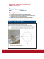
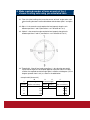
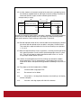
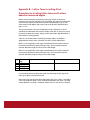
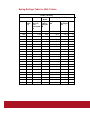
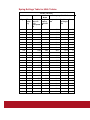
1
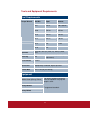
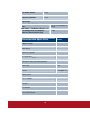
SERVICE MANUAL
Gaia-Wind 11 kW Turbine
Your own
Wind Turbine
Copyright © 2008
Gaia-Wind Ltd.
1 Ainslie Road
Hillington Park
Glasgow G52 4RU
United Kingdom
Tel: +44 (0) 845 871 4242
E: [email protected]
Reference number: GW-UK-20-0808 Service Manual
Document revised:
August 2008
All illustrations and photographs Copyright © Gaia-Wind. No part of this
manual may be transmitted into any form by any means without
permission from Gaia-Wind. The information given in this user manual is
believed to be accurate and reliable at time of printing. All specifications
are subject to change without prior notice
2
Table of Contents
Health and Safety Information
6
Tools and Equipment Requirements
9
Tool Requirements
9
Equipment
9
Recommended Spare Parts
10
Introduction
12
Overview
12
Servicing Intervals
Three Month Service
Annual Service
12
12
13
Servicing Checklist
13
Servicing Log
13
Necessary Controller Procedures
14
Acquiring Access Rights & Active Status
14
Releasing Active Status & Access Rights
16
Resetting Error Menu
17
Accessing System Production
19
1. Functionality Test
21
Start the Turbine
21
Record Wind Speed and Power Output
21
Turbine Observations
22
Manual Stop Test
22
Emergency Stop Test
23
2. Sensor Inspection
24
Cable Twist Sensor
24
RPM Sensors
25
Anemometer
26
Vibration Sensor
27
Brake Worn Sensor
27
3. Visual Inspection
28
Teeter-Hub
28
3
Blade
28
Nacelle
29
Bearing
29
Cables s
29
4. Brake Inspection & Functionality Test
31
4.1 Calibrate Brake
31
Change Operational Parameters
32
Secure the Rotor
33
Brake On/Off
33
Check Brake Configuration
34
Brake Adjustment
35
Brake Caliper Inspection
35
Brake Sensor Positioning
36
Recheck Calibration
37
Release Rotor
37
Reset Operational Parameters
37
4.2 Tip Brake Test
38
Service Mode and Parameter Change
38
Deploy Tip Brakes
39
Reset Tip-Brakes
39
Reset Parameter Settings
40
Deactivate Service Mode
40
5. Greasing and Oil Change
41
Grease Main Bearing
41
Grease Yaw Bearing
41
5.2 Oil Change
42
Removing Oil
Method 1
Method 2
42
42
43
Applying New Oil
Method 1
Method 2
44
44
44
6. Nacelle Level
45
45
45
Lattice Tower
Tubular Tower
4
7. Bolt Inspection
46
7.1 Nacelle
46
7.2 Hub Assembly
51
Hub Brackets and Rubber Buffer
51
Blade Spring Brackets
51
7.3 Tower Bolts
52
Tubular Tower
52
Lattice Tower
53
Ladder Sections
53
Cable Guides (Lattice Tower Only)
54
Cable Twist Sensor
55
Electrical Connections
55
8. Untwisting of Cables
56
Disconnect Power and Signals Cables
56
Untwist Cables
57
Reattach Cables
57
9. Levelling Adjustments
58
Tubular Tower
58
Lattice Tower
59
10. Tubular Tower Grouting Procedure
60
Conclude Servicing
68
Service Checklist
68
Service Log
68
Restart the Turbine
69
Servicing Checklist
70
Gaia-Wind Servicing Log
81
Appendix A – Tubular Tower Levelling Chart
82
Appendix B – Lattice Tower Levelling Chart
90
Appendix C – Tip Brake Spring Settings
91
5
Health and Safety Information
Ensure
that
these
instructions
are
read
thoroughly and understood. It is essential that
they are retained, along with the remainder of the
manual,
as
they
contain
important
safety
information that must be adhered to.
•
It is compulsory that all personnel involved in the construction
and/or maintenance of the turbine wear appropriate personal
protective equipment (PPE) at all times; including, but not
limited to, a high visibility jacket, hard hat, and safety boots
Gloves are recommended to be worn to improve grip on the
ladder rungs and protect hands; Standard safety boots, with
steel reinforced toes to approved standards and non-slip soles;
a plastic helmet to approved standard with a chin strap to keep
the helmet in place.
•
Do not attempt to ascend the turbine tower and/or work on the
turbine should wind speeds exceed a value of 12 metres per
second
•
It is essential to ensure that all ladders, safety lines, and
working baskets are kept in clean working order at all times
•
Only one person is permitted to stand inside of the working
basket at any one time
6
•
Before ascending the tower, for any reason, the turbine must be
stopped and the main switch set to the off position
•
The nacelle must be locked with an anchor bolt before any work
is performed on, or near to, any rotating or moving parts
•
It should be ensured that during installation and maintenance
that there is always more than one person present at all times,
and that work does not continue in the event of adverse
weather conditions which could reduce safety.
•
All workers must be fully briefed on the sequence of operations
before commencement. This is to include the identification of
danger areas that must not be occupied during the servicing
procedures.
•
All personnel working at height must work according to the
requirements of the relevant statutory provisions, including the
use of PPE for working at heights. All personnel must have
been trained by a recognised body to work at heights, ideally a
BWEA Working at Height Training Course.
•
Existing site factors, e.g. overhead or underground electric
cables should be identified and an exclusion zone set
•
During installation and maintenance procedures which require
climbing of the tower, an appropriate safety harness for working
at heights must be worn at all times.
7
Double lanyards with
shock absorber should be used when climbing the ladder. A
work positioning device must be used when any work is
required which could take away the use of the climbers hands
as points of attachment to the tower.
•
Turbine electrical works are to be undertaken by experienced,
competent, and authorised personnel who are fully familiar with
the standard working practises within the electrical industry, and
who are acquainted with the maximum voltages present on the
system being installed.
•
Temporary signs, notices, and barriers should be erected if
required. If road closure is required this should be put in place
well in advance with the local authority.
•
Structural
and mechanical installation must
be actively
managed and supervised by a suitably experienced and
competent person.
•
The turbine’s electrical supply must be isolated for all works on
the electrical system.
8
Tools and Equipment Requirements
Tool Requirements
Torque Wrench
Bolt Dia
Span
Moment
M 27
NV 41
700-1100 Nm
M 20
NV 30
425 Nm
M 16
NV 24
210 Nm
M 14
NV 22
140 Nm
M 12
NV
18 Nm
M 10
NV
Spanners
M10, M12, M17(x2), M22 (x2), M24 (x2) M30,
M41
Allen Key
M6
Screw Drivers
Various
Spirit Level
Appropriately calibrated, digital spirit level
Anchor Bolt
M16 x 120 (for yaw locking)
Head cut-short (brake caliper
adjustment)
Equipment
Mobile Crane (Cherry Picker)
For access to tower and nacelle,
must be capable of carrying two
people + tools
Safety Harness
To approved standards
Safety Helmet
9
Zinc Based Aerosol
1 Can
Degreasing Solution
1 Can
Bag of Rags
Gearbox Oil – LE 1606 (annual service
only)
Main Rotor + Yaw Bearing Grease – LE
3751 Almaguard ®, vari-purpose
lubricant (annual service only)
11.4 ltrs. For complete oil
change
1 Tube
Recommended Spare Parts
Number
Rubber Bushings
2
Rotor Spring
4
Nylon Bush (Spring)
4
M12 Nyloc Nuts (Basket)
4
Locking Pin (rotor rod & spring bracket)
4
Brake Pads
1 Set
Sensors
1 Complete set
Lattice Tower
M 27 x 140 Bolt
2
M 27 Nut
2
M 27 Washer
4
M 14 x 30 Set Screw
8
10
M 14 Nuts
8
1 Set of Shims
Tubular Tower
M 27 Nut
4
M 27 Bushing
4
M 20 x 80 Bolt
4
M 20 Bolt
4
M 20 Washer
4
M 16 x 80 Bolt
4
M 16 Nut
4
M 16 Washer
4
M 14 x 30 Screw Set
4
M 14 Nuts
4
11
Introduction
Overview
This document provides information and instructions for performing
servicing on the Gaia-Wind 11kW turbine. The details provided herein
present the conventional sequence of servicing checks including full
inspections of the turbine controls, sensors, brakes, oil and grease, and
bolt connections.
Please take careful note of the health and safety instructions
summarised on the opening pages of this manual. In addition there is a
degree of safety procedures specific to individual tasks that must be
adhered to - these are detailed in the relevant sections of this manual.
Servicing Intervals
Three Month Service
It is required that a full inspection of the turbine is completed three
months after the installation of the turbine. All of the tests within this
manual should be performed during this service with the exception of
the greasing and oil changes outlined in section 5.
12
Annual Service
It is compulsory a full inspection and servicing of the turbine is
performed at least once a year. All of the tests and checks detailed in
this manual should be performed during the annual service with the
exception of the tubular tower grouting outlined in section 9, which
applies specifically to the three month service after installation.
Servicing Checklist
A Gaia-Wind servicing checklist accompanies this document. The tests
in the checklist correspond with the prescribed testing procedures
detailed within this manual.
It is compulsory that the checklist is completed throughout the course of
the servicing. Upon completion the checklist should be retained and a
copy sent to Gaia-Wind.
Servicing Log
Each turbine should have a servicing log located on the inside of the
controller.
The log must be completed after each service by the
servicing personnel. This includes details of the parts replaced and oil
changes. A spare copy of this log is included as an attachment to this
manual.
13
Necessary Controller Procedures
For many of the procedures outlined, it is required that access rights
and active status of the turbine controller are obtained. This can be
achieved by following the steps outlined below.
It is important that prior to leaving the turbine, that the access rights and
active status are disabled. Therefore the following procedure should be
followed upon completion of using the operating panel.
Acquiring Access Rights & Active Status
Step 1
Ensure
that
the
operating
panel is displaying the Start
Menu.
Step 2
Scroll down to the menu until
the
cursor
line
indicates
Scroll down
“Access Rights”
Press enter on the keypad.
Enter
Step 3
The
screen
display
will
change (right).
Enter the default user code:
456, using the numbers on the
operating panel, and confirm
by pressing enter.
14
Enter
The display will return to the
start menu, with Accessrights
99.
Step 4
Navigate the start menu down
until
the
cursor
indicates,
Scroll down
“Request active-stat”
Enter
Press enter on the keypad
Step 5
Enter the user ID: 1 and
Confirm by pressing enter on
the keypad
The screen will revert back to
the start
access
menu with both
rights
and
active
status.
Step 6
Ensure that the LED labelled
‘Active’ on the top right hand
side
of
the
keypad
is
illuminated. This confirms that
active
status
has
been
granted.
15
Enter
Releasing Active Status & Access Rights
Step 1
Ensure that the operating
panel display shows the Start
Menu.
Step 2
Navigate
down
the
until
start
menu
the
cursor
indicates, “Release activestat”
Enter
Press enter on the keypad
The display remains on the
start menu
Step 3
Navigate the start menu to
the line “Access Rights”.
Press enter on the keypad
two times.
Step 4
Enter
The display will revert to the
original start menu. You are
now
logged
out
of
the
turbine.
16
Additionally, the turbine operating panel is used to reset error
messages. Error messages will occur during the service as the turbine
controls are tested. It is required that these errors are reset after they
appear.
Resetting Error Menu
Step 1
Ensure that the Start Menu is
displayed on the keypad.
If you have not done so, obtain
Access
Rights
and
Active
Status.
See section 5.2.1 for
details
Step 2
Scroll down to the menu line
until the cursor is on the fourth
Scroll down
line “Status”.
Enter
Press enter on the keypad.
Step 3
The screen displays the recent
active
errors.
N.B.
if
no
Scroll down
information can be seen then
there are no active errors.
Scroll up
Navigate through the error list
using the cursor arrows.
17
Step 4
In the error menu press the
‘reset’ button on the keypad.
Reset
The error messages will be
erased.
If the error messages are not
erased, the error has not been
corrected.
Step 5
Press the escape button to
Escape
return to the main menu.
Step 6
The
turbine
will
start
automatically within 60 seconds
subject to availability of wind.
Alternatively, the turbine can be
started immediately by pressing
the start button.
18
Start
The servicing checklist and service log require the total turbine power
production to be detailed. By following the procedure below the total
system production is displayed on the operating panel display.
Accessing System Production
Step 1
Toggle through the menus
using the cursor directions
buttons
until
the
heading
displays ‘Status’.
Press enter on the Menu Line
Enter
‘System’.
The
system
submenu
will
appear on the screen.
Step 2
Navigate to the submenu line,
‘prod./consump.’, and press
Scroll Down
enter.
Enter
19
Step 3
The display should give a
selection of time frames over
which to view data.
With the cursor on total, press
Enter
enter.
Step 4
The final screen shows the
production
data.
The
important information here is
the
top
line,
the
energy
produced by the turbine.
Step 5
To return to the previous menu
Return to
Submenu
press escape.
To return to the Status menu,
hold control and escape.
20
Return to
Status
Menu
1. Functionality Test
Start the Turbine
If the turbine is not already running attempt to
manually start the turbine by pressing the start
button on the operating panel.
If wind speeds are low the turbine will utilise pulses from the ‘softstarter’. This will be evident as pulses are accompanied by a brief noise
and a negative power output.
If excessive pulses are required, and the turbine has not cut-in, then the
controller should display, ‘Motor start error’ – most likely for wind
speeds below 3m/s.
Should this occur reset the error and attempt to start the turbine when
wind conditions improve.
Record Wind Speed and Power Output
Record the wind speed and power
output from the turbine. This can be
read directly from the Start Menu on
the operating panel,
e.g.(right) Power = 4.2 kW
and Wind = 7.1 m/s
If possible, note the power output at a range of wind-speeds.
Enter this data to the section 1 of the servicing checklist.
21
Turbine Observations
Allow the turbine to run for several minutes and observe;
Are there any audible abnormal noises?
Describe any noises in the servicing checklist
Is there any visible shaking in the tower?
Detail any shaking in the servicing checklist
Is the turbine oriented with the rotor in the downwind direction?
Detail observations in the servicing checklist
If the turbine does not appear to be following the wind direction then pay
close attention to section 6 of this document.
Manual Stop Test
The turbine braking time should
be inspected in both high and
low wind conditions.
With the turbine running, press
the Stop button in the operating
panel.
This will activate the
turbine mechanical brake.
Count the time taken for the turbine rotor to come to a complete stop
from the moment the stop button is pressed.
22
The turbine should stop within 10 seconds, and a “Manual stop” error
will appear on the operating panel display.
Note the time taken and any observations on the servicing checklist.
Attempt to perform this procedure in both low (<4 m/s) and high
(>8? m/s) wind speeds.
If it is detected that it requires more than 10 seconds to stop the turbine,
pay close attention to section 4 of this manual.
Reset the ‘Manual stop’ error message on the controller before
continuing.
Emergency Stop Test
Test the turbine emergency stop
procedure
by
pressing
the
emergency stop button on the side
of the controller cabinet whilst the
turbine is running.
Record the wind speed and the
time taken for the turbine rotor to
come to a complete stop in the
servicing checklist.
Ensure that the turbine stops within 10 seconds and that an
“Emergency stop” error is recorded on the operating panel.
Upon completion of the test draw-back the emergency stop button, and
reset the error.
23
2. Sensor Inspection
It is required that all of the turbine sensors are inspected during the
annual service. To correctly execute the following inspection of the
turbine sensors two persons are required – one to manually stimulate
the sensor and the other recording results and resetting errors from the
operating panel.
Cable Twist Sensor
The
cable
twist
sensor
is
mounted to a steel tab located at
the bottom of the tower.
This
consists of a sensor unit and
guide arm, with a circular ring
through which the turbine output
cables are attached.
For the tubular tower, the cable
twist sensor is accessible through
the service hatch in the bottom
tower section.
With the turbine running – raise
the sensor guide arm and hold.
After a period of 1 minute the
turbine
should
automatically
shutdown.
24
A “Cable Twist” error message should appear on the operating keypad.
Note the results on the servicing checklist.
Reset the error before continuing.
RPM Sensors
The turbine has two separate RPM
sensors – a low speed sensor
located on the brake disc, and a
high
speed
sensor
on
the
generator.
Both low and high speed sensors
can be inspected by observing the
readings
from
the
turbine
controller.
These are located on
the second line of the start menu,
to the right of the wind speed
value.
During
normal
operation
the
reading should be approximately
56/1005.
25
Anemometer
The anemometer is located on the
upwind side of the turbine and
records the wind speeds at the
turbine hub height.
The wind speed reading from the
anemometer
is
located
on
the
second line of the start menu on the
turbine controller, displayed in m/s.
Observe the reading from the anemometer, and ensure that;
•
The reading appears appropriate for the given turbine power
output
•
The reading is steady, with no abrupt changes
Note any observations in the servicing checklist.
The following sets of inspections are to be
performed from the working basket.
demands the climbing of the tower.
This
Please
see the safety instructions outlined on the
opening pages for requirements.
26
Vibration Sensor
The vibration sensor is located in front
of the gearbox, above the main shaft.
Stimulate the sensor by oscillating the
top from side to side.
Ensure that the error is recorded as
on the operating panel screen as
“Vibration”.
Note the results in the servicing
checklist and reset the error before
continuing,
Brake Worn Sensor
The brake worn sensor is in the
form of a roller located beyond the
brake lever. In the event of wear
on the brake pads, the brake lever
will contact the roller, activating the
sensor.
Brake Worn Sensor
Manually rotate the sensor.
Ensure that a “Brake worn” error message is displayed on the turbine
operating panel, and note into the servicing checklist.
Reset the error before continuing.
27
3. Visual Inspection
From a suitable working platform perform a brief visual inspection of the
turbine copmponents listed below. Any excessive wear, visual damage,
or corrosion should be noted on the servicing checklist.
Teeter-Hub
Perform a visual inspection
of the teeter-hub assembly,
particularly
springs,
the
nylon
hub
bushings
and rubber buffers.
Note any wear or damage
in the servicing checklist.
`
Hub
spring
Blade
Perform a brief inspection
of the turbine blade.
Note any observations in
the servicing checklist.
28
Nylon
Bushing
Rubber
Buffer
Nacelle
Visually
Inspect
all
mountings and bushings
within the nacelle, for wear
or corrosion and check all
fastenings for tightness.
Note
into
the
servicing
checklist.
Main Bearing
Inspect the turbine main bearing, on the low speed drive at the outside
of the machine frame.
Inspect for any visible leaking of grease,
corrosion, or wear. Note any observations in the servicing checklist.
Cables s
First stop the turbine, isolate the supply to the controller and turbine and
wait 5 minutes before making the following checks which should be
performed only by suitably qualified personnel.
Inspect the external condition of all cables and the tightness of all high
voltage electrical terminals inside and outside of the nacelle.
29
Follow the table in the servicing checklist, noting condition of cables and
noting any loose connections and how many turns were required to retighten.
30
4. Brake Inspection & Functionality Test
4.1 Calibrate Brake
The brake caliper should be set as shown in the schematic below. This
shows the dimensions in the “brake off” position - an electromagnet is
holding the spring back at a compressed length of 90 mm, and the
brake disc is free to rotate. When there is a loss of grid or the stop
button is activated, the current to the electromagnet is cut and the
spring expands forward applying force to onto the brake caliper which in
turn applies a force onto the brake disk via the braks pads sufficient to
Figure 4A: Brake Schematic
stop the turbine rotor.
In order to inspect the calibration of the brakes it is required to alternate
between the “brake on” and “brake off” position.
This requires the
turbine to be connected to the electrical grid supply. Therefore, in order
to prevent the turbine motor starting the turbine parameters must be
changed, and the rotor secured before commencing. Only carry out this
procedure in light winds (<8 m/s).
31
To correctly execute the inspection and calibration of the braking
system two persons are required – one operating from the working
basket, the other on the ground using the turbine controller.
Change Operational Parameters
Ensure that full access rights and
active status has been acquired.
On the turbine operating panel toggle
to the parameter menu using the
keypad and select the “operation
control” submenu
Press enter on the line “Startwind”.
Enter the maximum value of 35 m/s
(thirty-five). This will ensure that the
turbine will not attempt to cut-in using
the soft starter.
Remaining on the “operational control”
submenu scroll down to the line “wing
parking”.
Press enter and change the value
from ON to OFF.
This will ensure that the turbine does
not attempt to park the blades.
32
Secure the Rotor
From inside of the working
basket
the
rotor
must
be
secured from rotation by tying a
suitably
rated
canvas
strap
between the brake disc and the
machine frame.
The strap should have a safe
working limit of at least 1000 kg.
The strap should be affixed to the two holes located on the brake disc,
and both sides of the machine frame. The strap should be tight and
secure and prevent the shaft from rotating in either direction.
Only once the rotation of the rotor has been secured should the
remainder of the inspection continue.
Brake On/Off
Ensure that all stop switches and isolators are released.
The personnel on the ground should start the
turbine by pressing the Start button on the
operating panel.
This action will cause the
spindle motor to extend bringing the electro
magnet in contact with the magnet anchor. The
spindle motor then retracts, releasing the brake.
33
The controller keypad should indicate that the brake is released. By
pressing the stop button the magnet is de-energised enabling the spring
to actuate the brake.
If the operating panel display indicates that there is an error – reset and
attempt to start the turbine again.
Check Brake Configuration
When the turbine is started by the
controller the brake should move
back to the “brake off” position
before being secured in place
with a retaining magnet. Whilst in
this position the distance between
the retaining magnet housing and
the end of the spring holder
should be measured – shown as
position 2 and 3 in the diagram
opposite respectively.
Note this distance in the turbine servicing checklist.
The critical dimension for this distance is 90mm – if the measurement
above is not consistent with this dimension then the brake must be
adjusted by following the instructions below.
34
Brake Adjustment
If required adjust the brake setup
using the following procedure;
1.
Loosen the tightening spring nut
(posn. 1.235)
2.
Rotate the spring holder (posn.
48.0) – the spring holder has an
internal nut welded to its inside
face
3.
Rotate the spring holder until
the 90 mm critical dimension is
achieved
4.
Secure the tightening nut back
against the spring holder
5.
Measure again to ensure that
the critical 90 mm distance has
been maintained
Brake Caliper Inspection
Set the brake in the “brake off”
position.
Visually inspect the brake caliper
and brake pads, and check for
any visible wear or damage.
Inspect the gap between the
brake pads and the brake disc.
35
The pads should be close to the
disc but without touching with
even spacing on both sides
If required the brake pads can be
adjusted using the grub screws
on either side of the calliper arms,
using a shortened 5 mm allen
key.
Grub Screw
Brake Sensor Positioning
The person in the working basket should ensure that all tools are
removed and his/her hands are clear from the nacelle.
From the ground the Stop button
should
be
pressed
on
the
operating panel.
The brake will move to the “brake
on” position.
Measure the distance between
the wheel of the brake worn
sensor and the end of the brake
assembly.
This distance should
be approximately 10 – 12 mm.
Record this information in the
servicing checklist.
36
If an adjustment is required this should be made by adjusting the
position of the sensor accordingly.
Recheck Calibration
Recheck all of the critical dimensions of the brake. This is necessary as
even slight adjustments on the brake pads can produce large changes
in the positioning of the lever arm.
This will require the turbine to be in the “brake off” mode once more.
From the operating panel on the ground, errors should be reset and the
start button pressed.
Recheck all of the critical dimensions in the three steps above, and
adjust accordingly if required.
Release Rotor
From the turbine operating panel the
Stop button must be pressed, and
hence the turbine in the “brake on”
position.
Remove the ratchet straps from the
brake disc
Reset Operational Parameters
Repeat the first step of the brake inspection procedure setting the
control parameters back to their original settings.
Start Wind: 3.5 m/s
Wing Parking: On
37
4.2 Tip Brake Test
The following procedure should be performed to test the turbine tip
brakes. This test is reliant upon wind conditions in the range of 4-6 m/s.
This procedure is performed with the turbine
rotor running at full speed.
No personnel
should be inside of the working basket or
ascending/descending the tower during the
test. Personnel not involved in the test should
stand clear of the turbine.
Service Mode and Parameter Change
Navigate to the service menu on the
operating panel.
Change Service Mode to ON
Change Running Away from 0 to 1
Navigate the operating panel to the
parameter menu.
On the RPM control submenu change
parameters to the following values;
WT Version
50Hz (UK, DK etc.)
60Hz (US etc.)
Max. Rotor:
From 62 to 68
From 66 to 75
Max. Generator:
From 1116 to 1300
From 1292 to 1500
38
On the brake control menu change;
WT Version
50Hz (UK, DK etc.)
60Hz (UK, DK etc.)
Max. Wheeling:
From 1120 to 1300
From 1320 to 1500
Deploy Tip Brakes
Start the turbine from the operating panel.
By setting the turbine to “run away” the rotor will speed up until the tip
brakes deploy. However the turbine may brake normally – if so it is
required that the operational parameters of the turbine are altered.
Note the wind speed and RPM at
which the tip-brakes deploy and
enter this onto the servicing
checklist.
Reset Tip-Brakes
Reset by rotating the blades
back
into
their
original
position using appropriate
working platform or tools to
do so.
39
Reset Parameter Settings
Return to the parameter menu and reset all values to their original
settings.
On the RPM control submenu change the values;
On the RPM control submenu change parameters to the following
values;
WT Version
50Hz (UK, DK etc.)
60Hz (US etc.)
Max. Rotor:
From 68 back to 62
From 75 to 66
Max. Generator:
From 1300 back to 1116
From 1500 back to 1292
On the brake control submenu change;
WT Version
50Hz (UK, DK etc.)
60Hz (UK, DK etc.)
Max. Wheeling:
From 1300 back to 1120
From 1500 back to 1320
Deactivate Service Mode
Navigate to the service menu on the operating panel.
Change Service Mode to OFF
Change Running Away to 0
Reset any errors in the turbine.
40
5. Greasing and Oil Change
Greasing and oil changes form a component of
the annual service of the turbine only, and are
not required for the three month service.
5.1 Grease Bearings
Grease Main Bearing
Remove all excess grease from the outside of the main bearing using a
rag.
Using a grease gun apply the LE3751 grease through the nipple on the
top of the main bearing. Continue to apply grease until it is detected
that excess grease is excreted through the outside of the bearing.
Remove any residual grease using the rag.
Grease Yaw Bearing
Remove all excess grease from the outside of the yaw bearing using
rag.
There are 5 greasing nipples located around the outside of the yaw
bearing. Repeat the procedure for the main bearing for each of the 5
greasing points.
41
5.2 Oil Change
We recommend that the gearbox oil should be changed after 5 years of
service. However, on high production sites it is advisable to take an oil
sample after 3 years and have it analysed for deterioration or particle
build up. To determine if an oil change is required it is necessary to
consult the turbine servicing checklist from the previous service(s) and
service log. The servicing company should retain the checklist after
each annual service.
There are two prescribed methods for changing the gearbox oil detailed
below.
Removing Oil
Method 1
A complete change of the gearbox oil requires two double action hand
pumps - one for the removal of existing oil and the other for refilling with
new oil. In addition an empty oil drum (or equivalent) for collection, and
11.4 litres of gearbox oil (LE 1606).
Appropriate personal protective equipment, including safety goggles,
must be worn at all times.
From the working basket or mobile platform remove the gearbox
breather lid.
42
Using the pump for oil removal, feed the flexible tube into the top of the
gearbox, and pump the gearbox oil into the empty drum. Continue until
no further oil can be extracted.
With a spanner, unscrew the plug from the underside of the gearbox.
Remove any residual oil from the base of the gearbox.
Refit the plug on the underside of the gearbox.
Method 2
A complete change of the gearbox oil requires one large funnel, an
empty oil drum (or equivalent) for collection, and 11.5 litres of gearbox
oil (LE 1606).
Appropriate personal protective equipment, including safety goggles,
must be worn at all times.
Manually yaw the nacelle until the rotor is aligned on the same side as
the ladder. Lock the nacelle in this position with an anchor bolt (M16 x
120).
From the working basket remove the gearbox breather lid.
Operating from the ladder, remove the plug from the underside of the
gearbox.
Place funnel below plug and tap the gearbox oil into the
empty oil drum.
When gearbox oil is fully drained, refit the plug on the underside of the
gearbox.
43
Applying New Oil
Method 1
Using the pump for oil application, feed the output flexible tube into the
top of the gearbox, and the input tube into the drum of new oil.
Pump oil into the gearbox until level is shown to be at the midpoint of
the side glass.
Reapply the gearbox breather lid and remove any overflow oil from
using a rag.
Method 2
From the working basket use the funnel the new oil through the gearbox
breather.
Fill gearbox with the oil until level is shown to be at the midpoint of the
side glass
44
6. Nacelle Level
Measure Nacelle Bias
It is required that the levelling of the turbine nacelle is checked in order
to prevent against a yaw bias which could cause the rotor to align in one
particular direction.
Lattice Tower
The tower is levelled with reference to four points around the tower. For
the lattice tower this is relative to each of the four tower legs.
Rotate nacelle and record level above each of the four tower legs by
placing the electronic spirit level onto the machine frame above the yaw
bearing. Record these values into section 6 of the servicing checklist.
If an imbalance of over 0.3 degrees is recorded in the tower then the
turbine levelling procedure will need to be performed. This is detailed in
section 9 of this manual.
Tubular Tower
The tubular tower is fixed onto sixteen M27 nuts in a circle around the
tower base flange. The tower is levelled with reference to four of these
nuts equally spaced around the bolt circle (labelled 1, 5, 9, and 13).
The position of these bolts should have been clearly identified during
the turbine installation.
45
Rotate nacelle and record level above each of the four nuts by placing
the electronic spirit level onto the machine frame above the yaw
bearing. Record these values into section 6 of the servicing checklist.
If an imbalance of over 0.3 degrees is recorded in the tower then the
turbine levelling procedure will need to be performed. This is detailed in
section 9 of this manual.
7. Bolt Inspection
Certain bolts in the tower, nacelle, and hub must be inspected during
the annual servicing of the turbine. This includes a visual inspection for
signs of wear or corrosion. Additionally bolts must be tightened to the
correct torque as outlined below.
The importance of ensuring that all bolts are regularly tightened cannot
be understated, as this acts to protect bolts from fatigue.
All torque settings should be applied using an
accurately calibrated torque wrench. It should
be ensured that there are no gaps or breathing
in the flange connections.
7.1 Nacelle
46
It is required that certain connections within the nacelle are inspected
and tightened. This should include all mountings and fittings for the
generator, gearbox, bearing, as well as all sensor fittings.
Figure 7A: Nacelle
Components
1. Rotor Blades
2. Hub fork
3. Main Bearing
4. Main shaft
5. Vibration Sensor
6. Gearbox
7. Brake Disc
8. Flexible Coupling
9. Generator
10. Generator RPM
Sensor
11. Anemometer
12. Break Sensor
13. Brake
14. Rotor RPM Sensor
15. Retaining Magnet
16. Spindle motor
Ensure that the turbine is stopped, the main
switch set to the off position, and the electrical
supply isolated for the following service
checks.
47
48
49
Posn
Component
Location
Thread
Number
Torque
(Nm)
7.1.1
Bearing
Housing
Flange
M20 x 70
4
400
7.1.2
Main Shaft
nut
Main shaft – at
gearbox
M80
1
Hand tight
Rotor rpm
sensor plate
Gearbox
mounting
blocks
Gearbox
mounting
blocks
Gearbox
fittings
Main shaft – at
gearbox
M16 x 50
1
210
Either side of
machine frame
M16 x 90
4
210
Either side of
machine frame
M16 x 110
2
210
Either side of
gearbox
M20 x 50
8
400
7.1.3
7.1.4
7.1.5
7.1.6
7.1.7
Brake Disc
On sleeve of
brake disk
M8 x 25
1
18
7.1.8
Flexible
coupling
Brake disc
M8 x 70
6
25
Generator
flange
M8 x 70
6
25
Rear of machine
Frame
M12 x 25
4
85
Rear of machine
Frame
M10 x 30
2
Hand-tight
Gear box
M16 x 40
2
210
Caliper
Mounting Plate
M10 x 60
2
49
Underside of
machine frame
M12 x 40
4
85
7.1.9
7.1.10
7.1.11
7.1.12
7.1.13
7.1.14
Flexible
coupling
Generator
rubber
mounting
bushings
Anemometer
Mechanical
brake caliper
fitting
Mechanical
brake
calliper fitting
Working
Basket
50
7.2 Hub Assembly
Hub Brackets and Rubber Buffer
From the working platform tighten
the connectors on the hub spring
bracket and rubber buffers.
Hub Spring Bracket
Bolt/Nut Size: M20
Number of Connections: 4
Tightening Torque: 400 Nm
Rubber Buffer
Bolt size: M16
Number of Connections: 2
Tightening Torque: 210 Nm
Blade Spring Brackets
From the working platform tighten the
connectors on the blade spring bracket.
There are two blade spring brackets, one
at either side of the hub.
Blade Spring Bracket
Bolt/Nut Size: M10
Tightening Torque: 18Nm
51
7.3 Tower Bolts
Tubular Tower
The diagram below shows the
position of the flanges for the
tubular tower.
The table below
relates each flange to the correct
bolt size and tightening torque.
There are 16 connectors between
the top flange of the tower
(Flange A) and the yaw bearing
on the underside of the nacelle.
There are 16 bolts connecting the
tower sections at the interfaces
labelled Flange B and Flange C.
Check and tighten each of the
tower bolts from a mobile working
platform
(MWP).
Ensure
all
Flange
personnel have been trained to
work
on
A
B
C
D
the mobile working
platform and that a full and proper
risk
assessment
has
been
conducted prior to working being
carried out.
52
Bolt
Size
M16
M16
M20
M27
Tightening
Torque
210 Nm
210 Nm
400 Nm
700 Nm
Lattice Tower
The lattice tower sections are connected with four bolts that are located
on the inside of the tower legs (equivalent to Flanges B and C in the
diagram above). From the working basket, ladder, or working platform
the following connectors should be examined.
Bolt Size: M 27
Tightening Torque: 1100 Nm
There is an end plate on the top
section of the lattice tower,
which connects to the yaw
bearing on the underside of the
nacelle. This is the similar to
Flange A on the tubular tower;
Bolt size: M16
Tightening Torque: 210 Nm
Ladder Sections
The
ladder
sections
are
connected to the brackets welded
onto the outside of the tower.
There are three separate ladder
sections corresponding to each of
the tower sections.
Ensure that all of the connecting bolts are correctly tightened to;
Bolt/Nut Size:
M14
Tightening Torque: 140 Nm
53
Cable Guides (Lattice Tower Only)
There are three cable guides on
the lattice tower – one in the
middle of each of the tower
sections. The cable guide arm is
mounted to the inside of the
tower leg.
Ensure
that
the
bolts
the
connections are tightened to;
Bolt size: M10
Tightening Torque: Hand tighten
Where the turbine output cables
pass through the guide they are
shielded with a protective plastic
hose.
Inspect the hosing and ensure
that
there
is
no
excessive
damage.
54
Cable Twist Sensor
The cable twist sensor unit is
mounted to a steel lug located
at the bottom of the tower.
Check all fasteners – secure
hand tight.
Electrical Connections
The turbine power cable and
signal cables terminate in two
control boxes located on the
inside of the controller.
Ensuring
that
the
turbine
electrical supply is isolated, and
wait for 5 minutes to ensure that
the
capacitors
are
fully
discharged.
Tighten each of the connectors
firmly hand tight as per the
Servicing Checklist.
55
8. Untwisting of Cables
A consequence of the turbine’s free yaw design is that the power and
signals cables that run down the length of the tower may become
twisted. Excessive twisting will generate a cable twist error and stop the
turbine. The cables should be manually untwisted during the annaul
servicing of the turbine.
Before commencing any work on the electrical
parts of the turbine, ensure that the supply is
isolated and then wait a further 5 minutes to
allow for full discharge of the capacitors
Disconnect Power and Signals Cables
Unfasten the turbine output
cables from the cable twist
sensor arm by cutting the cable
ties holding them in place.
Remove the power and signals
cables from the underside of
the controller.
Lattice
tower:
Un-hook
the
cable clamp that hangs on the
diagonal tower brace. Tubular
tower: Un-hook cable clamp
from hanger fitted to inside
tower base.
56
Untwist Cables
Manually untwist the turbine
cables.
For the lattice tower, this can
be accomplished standing on
the inside of the tower base.
For the tubular tower, use the
servicing hatch on the bottom
tower section.
Reattach Cables
When completed, reattach the power and signals cables to the cable
twist sensor arm using cable ties and re-hang cable clamp.
Reattach cables to their original position in the underside of the turbine
controller, ensuring cable glands are tight-fitting and cannot come loose.
57
9. Levelling Adjustments
If the measurement for the horizontal level of the nacelle determined
during section 5 of this document determined a significant imbalance
then the following levelling procedures should be performed for the
tubular and lattice towers respectively.
Never make adjustments when there are
personnel
inside
the
working
basket
or
ascending/descending the turbine.
Tubular Tower
The tubular tower is secured at
the base onto sixteen 27 mm
threaded
rods
that
the
are
embedded
in
turbine
foundation.
Each connection
contains a bolt, spacer bushing,
a levelling nut below the flange
and a tightening nut above.
The tower is balanced with reference to the Tubular or Lattice Tower
Levelling Charts, included as Appendices A and B respectively.
Based on the levelling recordings in section 6 the exact adjustment of
the tower bolts can be read from the chart.
1. From Section 6, is it required to carry out turbine levelling?
2. Carefully follow the levelling procedure in Appendix A (for Tubular
Tower) or Appendix B (for Lattice Tower)
3. Record the final values in the service check list.
58
Lattice Tower
The lattice tower is fastened to the
four foundation legs with an M27 nut,
bolt and spacer for each.
The tower
is balanced by
the
insertion of metal shims between the
tower leg and foundation base. The
lattice tower levelling chart, included
as an appendix to this document
specifies the shims required based
on the levelling recordings in section
6 of this manual.
1. Using a digital level, measure the angle of each tower leg at a
height of 1 meter above the tower foot to the centr of the level.
2. Record this value and compare to previous recordings to
determine any tower movement.
3. To level tower add or remove the necessary amount of shims,
according to the the lattice tower levelling chart and the
recordings in section 6.
4. Tighten all nuts to 1100 Nm.
5. From the working basket, the level of the drive train above the
machine frame should be rechecked. If suitably level proceed, if
not repeat until balance is achieved.
6. Record final values in the service check list.
59
10. Tubular Tower Grouting Procedure
The pouring of grout beneath the bottom
flange applies for the three month servicing of
turbines with a tubular tower only.
Grouting underneath the bottom flange of the tubular tower prevents
build up of standing water which could create an environment for
corrosion. There must also be a drain pipe fitted from the inside of the
tower passing though the out side polypropylene form work to allow any
water to drain out.
60
DETAIL A
Required Materials
Material
Qty
1. Grout:
Conbextra HF (High Flow)
4-5 no. 25Kg bags
2. Polypropylene sheets or
equivalent flexible material
(at least 5mm thick)
1 sheet made up to 150mm height x 3.0m in length
1 sheet made up to 150mm height x 4.5m in length
3. Small nuts and screws
As required to connect strips
4. Drainage pipe
1 no. (diameter approx 20-30mm, length 500mm)
Application Instruction:
Preparation:
The substrate surface must be free from oil, grease or any loosely
adherent material. If the concrete surface is defective or has a laitance,
it must be cut back to a sound base. Bolt holes and fixings pockets must
be blown clean of any dirt or debris.
61
Pre- Soaking:
For a minimum of 2 hours prior to grouting, the area cleaned foundation
should be flooded with fresh clean water. Immediately before grouting
takes place, any free water should be removed. Particular care should
be taken to blow out any bolt holes or pockets.
Formwork
The form work should be constructed to be leak proof as Conbextra HF
is a free-flowing grout. A polypropylene strip should be fitted to the
inside and outside of the tower base flange.
Step
Photograph
1. Cut first sheet to 150mm
height x 3.0m in length
bolting together as
necessary
2. Cut second sheet to
150mm height x 4.5m in
length bolting together as
necessary
62
3. Take first sheet full
assembled and feed
through tower hatch
4. Press down into place
until tight against the ID of
the tower at the bottom
where it meets the
concrete foundation
5. Once in place and
pressing firmly against the
ID of the tower mark the
overlap using a white
marker pen or something
else suitable.
63
6. Remove the strip again
through the tower hatch
and bolt together
accordingly ensuring the
perimeter is exactly as per
the overlap mark
7. Cut a suitably sized hole
for the drainage pipe and
insert drainage pipe. Hole
should be no bigger than
the pipe diameter so that
when inserted the pipe is
held firmly in place. Hole
should be approx 5mm
from the edge at the
bottom of the
polypropylene strip.
8. Place the strip against the
tower ID taking care to
ensure drainage pipe exits
under flange and that
there is a downwards
gradient to take standing
water from inside the
tower radially outwards to
exit on the outside.
Ensure there are no gaps
between strip and
concrete foundation.
64
9. Apply silicon sealant
between polypropylene
strip and concrete
foundation
10. Cut second sheet to
150mm height x 4.5m in
length bolting together as
necessary and ensuring
the diameter is at least
100mm from the edge of
the bottom flange of the
tower. It must be ensured
that the interface between
this second strip and the
concrete foundation is
sealed and tight to prevent
leakage of the grout when
poured. Use sealant if
required. Cut hole in
second strip to hold
drainage pipe and ensure
downward gradient is
maintained.
65
11. Mix the grout according to
directions on packaging.
For best results a
mechanically powered
grout mixer should be
used. For quantities up to
50 Kg a Bosch(or
equivalent) 1150 watt 280
to 640 rpm 110 volt drill,
fitted with a Conbextra
mixing paddle is suitable.
The amount of clean
water that is to be added
◦
to a 25 kg bag at 20 C is:
Flow-able
4.5 liters
Fluid
4.8 liters
12. Pour grout within
formwork taking care not
to splash or overflow onto
tower flange
13. Once up to level of flange
ensure mixture has fully
filled out under the flange
and is even,
homogeneous and free
from lumps
66
14. Leave to set
15. Rap the exposed
foundation rods and nuts
in Densotape, ensuring
that none of the rods are
exposed to atmosphere.
Wear rubber gloves when
applying denso tape. It is
essential that the parts are
clean from grease or scale
before applying the tape.
67
Conclude Servicing
Service Checklist
Ensure that the service checklist has been completed, including the
information on the opening page, signed and dated by the servicing
engineer.
Upon completion the Service Checklist should be retained by the
servicing company and a copy sent to Gaia-Wind.
Service Log
Complete the turbine servicing log on the inside of the controller. If
there is not already a service log then enter information into a new log
sheet – a copy of which is attached to this manual – entering the
customer name and turbine ID number.
On the log sheet enter the date, the total turbine production up to the
date of service, and name of service engineer and company. Most
importantly, enter specific servicing information into the space provided,
for example detail if an oil change or tower levelling was completed, or
worn parts replaced and all measurements made.
68
Restart the Turbine
Before leaving the turbine ensure that all tools and equipment have
been cleared from the working basket and turbine surroundings.
Additionally, ensure that all anchor bolts and restraints have been
removed.
Ensure that all turbine isolators and stop buttons are released and reset
any active errors displayed on the operating panel then release active
status.
Start the turbine and allow it to run for several minutes.
Ensure that the turbine is operating effectively and that there are no
abnormal noises or movements before leaving the site.
69
Gaia-Wind 11kW Turbine
Servicing Checklist
To be completed by the servicing personnel
Date
Service
Performed by
Customer
Servicing
Company
Customer
Address
Turbine I.D. no
Annual/Three
month service
Total System
Production
•
Service Number
(year 1, 2, 3 etc.)
This document details the tests and inspections as part of the
standard service for the Gaia-Wind 11kW wind turbine.
•
The standard procedures for the safe testing and inspections are
detailed in the Gaia-Wind 11kW Service Manual which details the
equipment, parts, and specific health and safety information
relating to the service.
•
All personnel concerned with servicing the turbine must have read
and be familiar with the procedures in the servicing manual, and
comply with all of the health and safety instructions outlined.
•
If there is any uncertainty concerning any of the procedures, or to
obtain a copy of the servicing manual, contact Gaia-Wind.
•
All procedures must be performed by Gaia-Wind accredited
servicing company
1. Functionality Tests
COMMENT
1.1 Starting the Turbine
1.1.1
Was the soft-starter
required to start the
turbine?
1.1.2
If the soft-starter was
required, how many
pulses did it take to start
the turbine?
1.1.3
Was a ‘Motor start
error’, recorded by the
turbine controller?
1.1.4
What is the recorded
wind speed and power
output?
1.1.5
Power output over a
range of wind speeds
(where possible).
YES
NO
YES
NO
WIND
SPEED
M/S
POWER
OUTPUT
KW
WIND
SPEED
(M/S)
POWER
(KW)
1.2 Turbine Observations
1.2.1
Are there any audible
abnormal noises?
YES
NO
1.2.2
Is there any shaking in
the tower?
YES
NO
1.2.3
Is the turbine oriented
in a downwind
position?
YES
NO
1.3 Stopping Inspection
Low wind
1.3.1
1.3.2
Manual Stop Test
How long did it take to
fully stop the turbine,
measured from the
moment the “stop” button
is pressed on the
controller keypad?
Emergency Stop Test
How long did it take to
fully stop the turbine,
measured from the
moment the emergency
stop button is pressed?
2. Sensor Inspection
2.1
Cable Twist
Sensor
High
Speed
2.2
RPM
Sensors
2.3
Anemometer
2.4
Vibration
2.5
Brake Release
Sensor
2.6
Brake Worn
Sensor
Low
Speed
Wind Speed
m/s
Stopping time
s
High wind
Wind Speed
m/s
Stopping time
Wind Speed
s
m/s
Stopping time
Inspected
Yes
No
s
Operational
Yes
No
Comment
3. Visual Inspection
3.1
Teeter-Hub
3.2
Blade
3.3
Nacelle
3.4
Main Bearing
3.5
Cables & Terminals
Comment
Complete checklist below
Cable & Terminals- Inspection Checklist
Code
Component
Description
Model/ serial
no.
IC100
Computer
IC1000
A6.8
Display
Current
Transformer 1
Current
Transformer 2
Current
Transformer 3
WP3059
GK Amp
100/1 VA 2.5
GK Amp
100/1 VA 2.5
GK Amp
100/1 VA 2.5
Contactor
Motor Guard
(circuit breaker)
Autofuse 24V
AC
Autofuse 220V
trafo 24V AC
Autofuse 220V
trafo 24V AC
LC1D18
GV2ME20/
13-18A
C60N C10
400V ~
C60N C2
230/400V ~
C60N C6
230/400V ~
Relay Actuator
T1.8
T1.9
T1.10
K9.2
Q3.2
F4.4
F6.2
F7.2
K10.2
K10.4
Relay brake coil
24V DC
MT 78 740
10A 250V
T6.1
Transfo 24V AC
STT 0.075
T7.1
Transfo 24V AC
STT 0.075
V7.4
Bridge Circuit
SPD 24120
Check
Cable
condition
Check
terminals
( )
( )
Tight
Turns req'd
to re-tighten
Yes/no
Comments
24VDV-5A
C7.4
Electrolyte
V2.2
Soft Starter
K9.4
X5.4
By-pass relay
Contactor
phase
compensation
Service socket
220V
X1
Terminal strip
X1
X2
End stop
Control cable
socket
C3.2
Phase
compensation
(capacitors)
K11.2
4700/63V
screwterm
P-LINE
SMC3DA4025
LC1D18/
LC1D25
LC1-DFK11B7
24VDC 10A
DIN LMJ16A
15310
2.5-4mm
RK2.5-4PA
2.5-4mm
AP2.5-10PA
2.5-35KL
ES35PA
Varplus2
10/10.75kVAr
400/415V
50Hz
4. Brake Inspection
4.1 Calibrate Brake
Ensure the brake control parameters have been reset and the turbine rotor secured before
performing any work on the brake system. Consult the servicing and maintenance
manual for full details.
4.1.1
Measured distance between the
retaining magnet housing and
spring holder in “brake off”
position
4.1.2
Brake adjustment performed
4.1.3
Brake Caliper check
4.1.4
Distance between brake worn
sensor and brake assembly
mm
YES
No
YES
No
mm
4.2 Tip Brake Test
YES
4.2.1
No
Tip brakes deploy
If no to 4.2.1 adjust spring length on blade tip according to table in Appendix C
4.2.2
Conditions for tip
brake deployment
Wind speed
m/s
Rotor Speed
RPM
5. Greasing and Oil Change
(Annual Service Only)
5.1 Grease Bearings
5.1.1
Main bearing greased
5.1.2
Yaw bearing greased
Yes
Comment
No
5.2 Oil Change (After 1st Year then every 3-5 Years)
5.2.1
When was the last oil change
performed?
years
5.2.2
Was an oil change performed
during this service?
Yes
No
6. Nacelle Level
6.1
Are there any visual
indications of yaw bias – is
the rotor aligned in the
downwind direction?
Tubular
6.2.1
Record angle of deviation
from the horizontal on the
machine frame of the nacelle
when pointing the rotor at
each of the four designated
locations (degrees)
Lattice
6.2.2
6.4
Record angle of deviation
from the horizontal on the
machine frame of the nacelle
when pointing the rotor at
each of the four designated
locations (degrees)
Is a tower levelling procedure
to be performed? (imbalance
greater than +/- 0.3 degrees)
If Yes, go to section 9
Comment
Yes
No
Location 1
Location 5
Location 9
Location 13
4
Leg 1
3
Leg 2
Leg 3
1
Leg 4
Yes
No
2
7. Bolt Inspections
Comment
Inspected
Tightened
to
7.1 Nacelle
Yes
No
7.1.1
Bearing housing
Nm
7.1.2
Main Shaft nut
Nm
7.1.3
Rotor rpm sensor
plate
Nm
7.1.4
Gear Mounting
Blocks
Nm
7.1.5
Gear Mounting
Blocks
Nm
7.1.6
Gearbox Fittings
Nm
7.1.7
Brake Disc
Nm
7.1.8
Flexible coupling
(brake disk)
Nm
7.1.9
Flexible coupling
(generator flange)
Nm
7.1.10
Generator rubber
mounting bushings
Nm
7.1.11
Anemometer
7.1.12
Mechanical brake
caliper fitting
Nm
7.1.13
Caliper mounting
plate
Nm
7.1.14
Working Basket
Nm
7.2 Hub Assembly
7.2.1
Hub Spring Bracket
7.2.2
7.2.3
Rubber Buffer
Blade Spring
Bracket
7.3 Tower
Tubular Tower
TO BE COMPLETED FOR TUBULAR TOWERS ONLY
7.3.1
Flange A – 16 bolts
Nm
7.3.2
Flange B – 16 Bolts
Nm
7.3.3
Flange C – 16 Bolts
Nm
7.3.4
Working Basket
Nm
7.3.5
Ladder Sections
Nm
7.3.6
Cable-Twist Sensor
Nm
7.3.7
Electrical
Connections
Lattice Tower
TO BE COMPLETED FOR LATTICE TOWERS ONLY
7.3.1
Flange A – 16 bolts
Nm
7.3.2
Flange B – 16 Bolts
Nm
7.3.3
Flange C – 16 Bolts
Nm
7.3.4
Working Basket
Nm
7.3.5
Ladder Sections
Nm
7.3.6
Cable-Twist Sensor
Nm
7.3.7
Cable Guides
7.3.8
Electrical
Connections
8. Untwisting of Cables
8.1
Yes
No
Comment
Cable untwisting performed?
9. Turbine Levelling
9.1
Nm
Yes
No
Comment
From section 6 is turbine
levelling required?
Tubular
Posn 1 ____deg
Posn 5 ____deg
Posn 9 ____deg
Posn 13 ____deg
9.2
Record angle of tower at a
point 1 metre above bottom
flange and sketch rough
schematic of positions
relative to a landmark or
reference point (road,
house, North etc)
9.3
Has turbine levelling been
completed according to
Appendix A or B?
Sketch
Lattice
Leg 1
Leg 2
Leg 3
Leg 4
____
____
____
____
Sketch
deg
deg
deg
deg
9.4
Final measured angle of
deviation from the
horizontal on the machine
frame of the nacelle
(degrees)
Posn 1 to 9
Posn 5 to13
10. Grouting Under
Tower (Tubular Only)
10.1
Three month service only:
Grouting procedure followed
as per guidelines in Section
10
Signed
Date
Yes
No
Comment
Gaia-Wind Servicing Log
CUSTOMER NAME
Date
Total Production
Turbine ID No.
Service Performed By
Service; oil change/replacement parts
Appendix A – Tubular Tower Levelling Chart
(3 Month Service Only)
Performed by:______________
Date: ___/___/___
Turbine ID No. __________
Summary/ Instructions
1. The Angle of the sides of the tower are measured at 4 locations
2. The level of the machine frame is measured in two directions by rotating the
nacelle to 4 positions at right angles to one another
3. Compare measured values and make a decision on levelling strategy
4. Using those results, the required number of turns on each of the 4 chosen
levelling nuts is determined with ease using the pre-calculated table
1. Measure Angle of Tower Sides
Angle in vertical direction of tower wall should be 89.16 deg
There are 16 bolts in the tower flange which are connected to the foundation.
1.1. Choose any of those 16 bolts and label it with the number 1 then count round
in a clockwise direction and label bolts 5, 9 and 13; writing on the tubular
tower with a marker pen just above the relevent bolt for reference later.
This gives us a numbering scheme according to fixed positions of the tower,
which will act as a datum for levelling
1.2. Measure angles at each of these points 1,5,9 & 13 using a digital spirit level at
a height of 1m above the bottom flange and record 3 values for each position
in columns B,C,D in the table below. Take an average of 3 measurements for
each position and enter this in column E in the table. Then calculate deviation
from the normal taper angle at that position by subtracting the average value
from 89.16 degrees and enter this value in column F.
Measured angle at
Measured angle at
Measured angle at
Measured angle at
B
C
D
F
Measured Angle
A
E
89.16 degPosition meas 1
meas 2
meas 3 average average
1
5
9
13
deg
deg
deg
deg
Shown below is an example of how this table should be completed:
B
Measured angle at
Measured angle at
Measured angle at
Measured angle at
A
Position
1
5
9
13
C
D
F
Measured Angle
E
89.16 degmeas 1
meas 2
meas 3 average average
89.2
89.1
88.9
89.1
0.09 deg
88.1
88
88.1
88.1
1.09 deg
89.1
89.2
89.1
89.1
0.03 deg
89.8
89.7
89.8
89.8
-0.61 deg
2. Measure Level of Machine Frame
The following should ideally be conducted in light winds so as to avoid significant
deflection of the tower due to wind thrust which could lead to measurement errors and
thus inaccurate levelling. If strong winds persist wait until there is a lull before taking
measurements
2.1. Climb tower using suitable PPA and from working basket and with the rotor
blade braked in the vertical and not horizontal position to minimise yaw
moments from the wind, move the nacelle around until shaft is axially algined
with position 1 and the rotor pointing outwards towards position 1
2.2. Place digital spirit level on underside of machine frame aligned axially with
shaft and record 3 measurements of angular deviation from horizontal, where
0 degrees is horizontal, then take the average. Sign convention is –ve for a
downwards angle from the horizontal as shown below;
Sign Convention (off-level exaggerated for illustration)
Horizontal
(0 deg)
-ve angle
2.3. Record measured angles in columns H,I,J and calaculate average in column K
Measured angle at
Measured angle at
Measured angle at
Measured angle at
H
I
J
Measured Angle
G
K
Position meas 1 meas 2 meas 3 average
1
5
9
13
deg
deg
deg
deg
3.
Compare Measured Values
3.1. Take measured values from column F and column K, then insert in table
below for comparison
3.2. Calculate deviation between measured values by subtracting values in column
K from those in column F and enter in column L in the table below:
A
Position
1
5
9
13
F
K
90 degaverage average
L
Deviation
(K-F)
deg
deg
deg
deg
3.3. An example table is shown below
Example Table
A
Position
1
5
9
13
F
L
K
Deviation
89.16 degaverage
average (K-F)
0.09
-0.57
-0.66
1.09
-0.10
-1.19
0.03
0.17
0.14
-0.61
-0.43
0.17
deg
deg
deg
deg
3.4. If a large discrepancy exists use value measured on machine frame as the
tower may not be true and the most important part to level is the machine
frame/ yaw bearing. Practically, if the modulus of the deviation value in
column L is >0.2 then use the values in column F for the levelling procedure,
hereafter referred to as the “off-level” angles.
4. Make required number of turns on each of the 4
chosen levelling nuts using pre-calculated table
4.1. From 3.4 of the levelling chart, enter the correct “off-level” angles to be used
when levelling the tower into the table below and calculate alpha 1 and alpha
2.
4.2. Alpha 1 is the corrective angle required to level properly along the axis
between positions 1 and 9 (convention= +ve in direction of 1 to 9)
4.3. Alpha 2 is the corrective angle required to level properly along the axis
between positions 5 and 13 (convention= +ve in direction of 5 to 13)
4.4. Theoretically, if the off-level angle at position 1 is -0.8 deg then one would
expect the off angle level at the point opposite at position 9 to be +0.8 deg
and thus the required corrective angle alpha 1 would be +0.8 degrees (i.e 0.8
degrees upwards from 1 to 9), as shown in the table below.
example table (theoretical)
M
N
O
P
A
off-level angle
Corrective angles
off-level angle
Position (before correction) alpha 1 alpha 2
(after correction)
1
-0.8
0.8
0.4
0 deg
5
-0.4
0 deg
9
0.8
0 deg
13
0.4
0 deg
4.5. In reality, however, the eccentric weight of the rotor on the yaw bearing causes
the nacelle to sag downwards at and angle of around -0.2 deg. Therefore, the
measured “off-level” angles are often something more like this;
example table (in reality)
M
N
O
P
A
off-level angle
Corrective angles
off-level angle
Position (before correction) alpha 1 alpha 2
(after correction)
1
-0.8
0.6
0.2
-0.2 deg
5
-0.4
-0.2 deg
9
0.4
-0.2 deg
13
0
-0.2 deg
Ultimately the corrective angles alpha 1 and alpha 2 should be set in order to achieve a
balance for a full 360 degree rotation of the yaw bearing in order to avoid yaw bias
which could lead to the nacelle sticking in one position in low winds.
4.6. Read off required number of turns from the table on the next page by selecting
the column with the desired values for alpha 1 and alpha 2 in order to level.
Then read off the required number of turns for each levelling nut at positions
1, 5, 9 & 13.
4.7. Make the required number of turns on positions 1 and 9 by loosening off all top
nuts expect at positions 5 and 13 which should be kept tight to act as a pivot
axis. Then raise or lower by making specified number of turns on 1 and 9
using an open ended spanner (NV 41).
4.8. Likewise, to make required turns on the levelling nuts beneath the bottom
flange at positions 5 and 13, keep positions 1 and 9 tight to act as a pivot,
loosen off all others and repeat levelling procedure according to no, of turns in
table.
4.9. Fully torque up all of the bottom bolts to 700Nm
4.10.
Climb the tower using proper PPA
4.11.
Re-measure level as before
4.12.
If level within +- 0.3 deg in both directions, then levelling is satisfactory
and thus complete.
4.13.
If out with +-0.3 deg, repeat until within this tolerance.
Appendix B – Lattice Tower Levelling Chart
Procedure for levelling lattice towers with shims
based on measured angles
Measure the horizontality of nacelle by measuring level on underside of
machine frame near the yaw bearing using a digital spirit meter and moving the
nacelle round so that the rotor points to the first identified point (leg 1), then
move around in 90 degree steps measuring the angle when positioned over
legs 2, 3 & 4..
These measurements will have already been made in Section 6.2.2 and it
should be considered that the eccentric weight of the rotor in reality may cause
the nacelle to point consistently slightly (usually around 0.2 deg) downwards in
the direction it is being pointed.
Take this into account when calculating the angles Alpha 1 and Alpha 2
(perpendicular to each other) and enter the values into the table below.
Alpha 1 is the magnitude of the angle created between the machine frame of
the nacelle and horizontal when pointing to leg 1, whilst accounting for the
constant downward angle resulting from the rotor weight.
Alpha 2 is the magnitude of the angle created between the machine frame of
the nacelle and horizontal when pointing to leg 2, whilst accounting for the
constant downward angle resulting from the rotor weight.
Leg
1
2
3
4
Angle at
Leg
Angle(1)=
Angle(2)=
Angle(3)=
Angle(4)=
Alpha 1
Alpha 2
Use the table below to calculate how much the foot flange of each leg has to
come up or down to make nacelle level.
After measuring and adjusting of the foot flanges with shims, Alpha 1 and Alpha
2 are measured once again. Once satisfied that deviations are within +-0.3 deg
in both directions, levelling is complete. Record values in the Service Checklist.
Appendix C – Tip Brake Spring Settings
Read blade tip number and tip mass off each end of the blade, which is visible
when the tips are deployed. The mass is also written on the Mounting Manual
which came with the turbine at delivery.
Read off the correct spring length from the table below, remove the inspection
plate on the blade and adjust the nyloc nut on the end of the threaded spring
rod to change the spring length. Once complete, re-attach the inspection plate.
Blade tip no.
Mass of blade tip
Required spring length
1
2
Kg
mm
Kg
mm
Spring Settings Table for 50Hz Turbine
50Hz Version
Calculated
N/Kg.
Tip
mass
Kg
Centripetal
force at
15%
overspeed
N
17
N/mm
req'd
spring
preload
N
Tool spring 1S38252 Green
compression
mm
Req'd
Spr.length
mm
N/mm
290
4
1160
1160
68.2
185.8
17
290
4.1
1189
1189
69.9
184.1
17
290
4.2
1218
1218
71.6
182.4
17
290
4.3
1247
1247
73.4
180.6
17
290
4.4
1276
1276
75.1
178.9
17
290
4.5
1305
1305
76.8
177.2
17
290
4.6
1334
1334
78.5
175.5
17
290
4.7
1363
1363
80.2
173.8
17
290
4.8
1392
1392
81.9
172.1
17
290
4.9
1421
1421
83.6
170.4
17
290
5
1450
1450
85.3
168.7
17
290
5.1
1479
1479
87
167.0
17
290
5.2
1508
1508
88.7
165.3
17
290
5.3
1537
1537
90.4
163.6
17
290
5.4
1566
1566
92.1
161.9
17
290
5.5
1595
1595
93.8
160.2
17
290
5.6
1624
1624
95.5
158.5
17
290
5.7
1653
1653
97.2
156.8
17
290
5.8
1682
1682
98.9
155.1
17
290
5.9
1711
1711
100.6
153.4
17
290
6
1740
1740
102.4
151.6
17
Spring Settings Table for 60Hz Turbine
60Hz Version
Calculated
N/Kg.
Tip
mass
Kg
Centripetal
force at
15%
overspeed
N
17
N/mm
req'd
spring
preload
N
Tool spring 1S38252 Green
compression
mm
Req'd
Spr.length
mm
N/mm
310
3.6
1116
1116
65.6
188.4
17
310
3.7
1147
1147
67.5
186.5
17
310
3.8
1178
1178
69.3
184.7
17
310
3.9
1209
1209
71.1
182.9
17
310
4
1240
1240
72.9
181.1
17
310
4.1
1271
1271
74.8
179.2
17
310
4.2
1302
1302
76.6
177.4
17
310
4.3
1333
1333
78.4
175.6
17
310
4.4
1364
1364
80.2
173.8
17
310
4.5
1395
1395
82.1
171.9
17
310
4.6
1426
1426
83.9
170.1
17
310
4.7
1457
1457
85.7
168.3
17
310
4.8
1488
1488
87.5
166.5
17
310
4.9
1519
1519
87.4
166.6
17
310
5
1550
1550
91.2
162.8
17
310
5.1
1581
1581
93
161.0
17
310
5.2
1612
1612
94.8
159.2
17
310
5.3
1643
1643
96.6
157.4
17
310
5.4
1674
1674
98.5
155.5
17
310
5.5
1705
1705
100.3
153.7
17
310
5.6
1736
1736
102.1
151.9
17
310
5.7
1767
1767
103.9
150.1
17
310
5.8
1798
1798
105.8
148.2
17
310
5.9
1829
1829
107.6
146.4
17
310
6
1860
1860
109.4
144.6
17
www.gaia-wind.com
Gaia-Wind Ltd, 1 ainslie Road, Hillington Park, Glasgow G52 4RU, Tel: +44 (0) 845 871 4242, E: [email protected]
Gaia-Wind document reference: GW-UK-20-0808 Service Manual