1
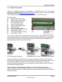
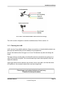
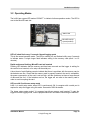
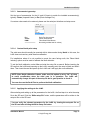
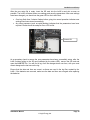
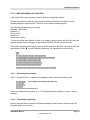
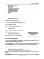
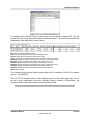
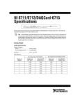
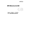
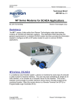
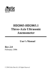
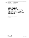
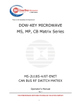
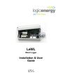
LeWL Wind Logger Installation & User Guide LeWL v7 Dec 2014 Revision Sheet Release No. Rev. 2 Rev. 5 Rev. 6 Rev. 7 Rev. 8 Rev. 9 Rev. 10 Date Revision Description 21-04-2009 23-06-2009 18-11-2009 10-04-2009 07-07-2011 07-09-2012 10-12-2014 Manual for LeWL version 5 Adaptation for LeWL version 5 menu Lewl_setup application New contact details Menu setup changes Layout changes, setup and sensor review Updated for LeWL hardware version 7 and firmware v7.0.3 Installation Manual Page 2 © Logic Energy Ltd. Important Notice You must read and agree to the License Agreement and conditions of use before you commence using the product. If you do not agree, you must return the whole package to the point of purchase. Disclaimers Logic Energy Ltd. assumes no responsibility nor liability for damages consequent to the user of this product. This document is being supplied to you solely for information purposes and may not be reproduced or distributed to any other person or parties in whole or in part for any purpose. The information provided in this manual is intended for instructional purposes only. This document is subject to change without notice and does not represent a commitment on the part of the manufacturer. Every effort has been made to make this guide as complete and as accurate as possible, but no warranty or fitness is implied. The author and the publisher shall have neither responsibility nor liability to any person or entity with respect to loss or damages arising from the use of information contained in this guide. Logic Energy Ltd accepts no responsibility or liability for errors, omissions, or misleading information that may be contained in this manual. Copyright This manual is copyrighted by Logic Energy Ltd. All rights are reserved. This document may not, in whole or in part, be copied, photocopied, reproduced, translated, or pre-produced on any electronic medium or machine-readable form without prior consent. © 2007 – 2014. Logic Energy Ltd. All rights reserved. Contact Details Logic Energy Ltd. 1 Ainslie Road Hillington Park Glasgow, G52 4RU Scotland, UK Web: www.logicenergy.com Installation Manual Page 3 © Logic Energy Ltd. TABLE OF CONTENTS 1 GENERAL INFORMATION......................................................................................................6 1.1 Safety................................................................................................................................ 6 1.2 Disclaimer......................................................................................................................... 6 2 INTRODUCTION...................................................................................................................... 8 2.1 System Overview.............................................................................................................8 2.2 Acronyms and Abbreviations.........................................................................................9 3 INSTALLATION AND SETUP................................................................................................11 3.1 Hardware Installation.....................................................................................................11 3.1.1 Mounting the LeWL.................................................................................................................. 11 3.1.2 Sensor Connection................................................................................................................... 12 3.1.3 Powering the LeWL.................................................................................................................. 13 3.2 Operating Modes............................................................................................................ 14 3.3 Logger Setup.................................................................................................................. 15 3.3.1 LeWL Setup via the SD card.................................................................................................... 15 3.3.1.1 Date and time setup.......................................................................................................... 16 3.3.1.2 Recording interval setup................................................................................................... 16 3.3.1.3 Anemometer type setup.................................................................................................... 17 3.3.1.4 Custom North point setup................................................................................................. 17 3.3.1.5 Applying the settings to the LeWL.....................................................................................17 3.3.2 LeWL Setup Menu via Serial Port............................................................................................ 19 3.3.2.1 Recording Interval setup................................................................................................... 19 3.3.2.2 Anemometer type setup.................................................................................................... 19 3.3.2.3 Date and time setup.......................................................................................................... 20 3.3.2.4 Custom North point setup................................................................................................. 20 4 DATA EXTRACTION.............................................................................................................. 21 4.1 Data on the MicroSD Card.............................................................................................21 4.2 Data on the Serial port...................................................................................................23 5 SPECIFICATIONS.................................................................................................................. 24 5.1 Physical Dimensions.....................................................................................................24 5.2 Technical Specification.................................................................................................24 6 TROUBLESHOOTING........................................................................................................... 25 7 WARRANTY........................................................................................................................... 27 Installation Manual Page 4 © Logic Energy Ltd. General Information GENERAL INFORMATION Installation Manual Page 5 © Logic Energy Ltd. General Information 1 GENERAL INFORMATION 1.1 Safety Contact with AC electrical mains can cause a severe electric shock and could be lethal Never remove the cover from LeWL if you are not sure what you are doing. Follow the set-up instructions in this manual with care to ensure all electrical connections are made properly. Do not connect any equipment to the battery supply until you have properly connected all the other leads. Never push anything into holes, slots or other openings in the LeWL unless specifically detailed in this document. All Logic Energy products have been designed with ease of use in mind. Caution: Do not use or store the LeWL device without its cover lid and/or open gland in hot, cold, damp or dusty places as this could affect the unit’s performance and may prove to be a fire hazard. Always ensure the lid is securely fastened and the gland is sealed and pointing downwards for reliable operation. Do not put anything on the LeWL device that could cause water damage (e.g. drinks, plants, etc). Do not place the LeWL on top of a unit which emits heat. The cover of the LeWL should never be removed while the unit is in operation, unless indicated by this manual. If for any reason the cover has been removed it should be replaced before operation begins A service of the unit should be carried out only by an authorised Logic Energy service centre or Logic Energy authorised engineer. 1.2 Disclaimer Under no circumstances will Logic Energy be liable for any direct, indirect, consequential or incidental damage, including loss of profits, business interruption and loss of data arising out of the use or the inability to use the software or hardware however caused, save to the extent that such liability is not capable of exclusion at law. These limitations of liability apply even if Logic Energy or a third party reseller have been advised of the possibility of such damage occurring. Installation Manual Page 6 © Logic Energy Ltd. Introduction INTRODUCTION Installation Manual Page 7 © Logic Energy Ltd. Introduction 2 INTRODUCTION 2.1 System Overview LeWL is an automatic stand-alone data logger that provides flexible and powerful data logging capabilities, specifically designed for the Energy Industry. LeWL features 2 digital pulse inputs and 2 analogue inputs. LeWL works with various anemometers and wind vanes in order to log real time wind speed and wind direction data onto a MicroSD flash memory card. Each data record has a date/time stamp when stored on the memory card. Data is stored as CSV (comma-separated values) files that are archived either by month or day depending on the pre-set logging interval. All data including settings are stored onto a MicroSD card (up to 2GByte capacity). This simplifies the collection of data - all that is required is to remove the memory card from the LeWL and insert it into a PC card reader/adapter. All stored files can be accessed with a standard text editor or any spreadsheet program like MS Excel or OpenOffice, or imported into analysis software. The LeWL wind logger is powered by two C-type alkaline batteries which provide up to 1 year operating time under normal conditions, when logging on 1 minute intervals or higher. Serial port for data and setup Powered by two C-type batteries 2x anemometer inputs 1x wind vane input 1x NTC temperature input MicroSD memory card for storing data files and for setup Installation Manual Cable gland and weatherproof enclosure Connector for Pro-D anemometer Page 8 © Logic Energy Ltd. 3.0 Installation 2.2 Acronyms and Abbreviations CSV: A data format originally known as comma-separated values (CSV). FAT16: Older version of the FAT file system used on smaller memory cards. FAT32: File Allocation Table, 32 bits; a modified form of the FAT16 file system. Hertz: Frequency in cycles per second, 1 hertz equals 1 cycle per second. IP65: Ingress Protection rating. 6 = totally sealed against dust; 5 = Protected against low pressure water jets from any direction. NTC: Negative Temperature Coefficient thermistor, an inexpensive and compact temperature sensor. RTC: Real Time Clock. RS232: Standardised connection system for connecting a device to the serial port of a computer or terminal. MicroSD: Micro Secure Digital, a small memory card available in sizes up to 2GB Installation Manual Page 9 © Logic Energy Ltd. 3.0 Installation INSTALLATION AND SETUP Installation Manual Page 10 © Logic Energy Ltd. Installation and Setup 3 INSTALLATION AND SETUP 3.1 Hardware Installation 3.1.1 Mounting the LeWL LeWL can be wall or pole mounted using the four holes provided inside each corner of the box. These are underneath the lid (Fig.1), as shown below. Use screws to mount the LeWL to a backing plate, or straps to fix the LeWL to a tubular mast. Ensure that the gland is facing downwards for maximum weather protection. Do not obstruct access to the lid. This will need to be removed to access the microSD card and batteries. Once the LeWL is in position and has been set up and started, fasten the lid with the included screws. Check that the lid seal is intact and the lid is securely fastened. Be careful not to lose any of the screws or insert them cross-threaded. Fig. 2 Fig. 1 Always make sure the logger is mounted with its gland facing down and the lid is securely fitted to avoid any possible water leaks (Fig.2) Installation Manual Page 11 © Logic Energy Ltd. Installation and Setup 3.1.2 Sensor Connection LeWL has 2 digital/pulse inputs for anemometers, 1 analogue input for the wind direction sensor, and an optional analogue input for an NTC temperature sensor. For a list of compatible wind sensors, please visit http://shop.logicenergy.com/ The connectors are labelled on the circuit board. See Fig. 3 for connector layout: From left to right: V+ Battery positive power (red) G Battery negative power (black) G Common ground (for NTC) T NTC temperature sensor G Common ground (spare) G Common ground (wind vane) D Wind vane signal D+ Wind vane power supply G Common ground (anemometer 2) A2 Anemometer 2 signal G Common ground (anemometer 1) A1 Anemometer 1 signal Fig.3 Anemometer pulse LEDs For Pro-D anemometers with a pre-fitted modular jack connector, disassemble the cable gland and pass the anemometer cable through the nut and the split-seal gland, then though the gland into the LeWL, and plug the connector into the socket on the circuit board. Reassemble the gland and tighten so that it seals onto the cable. Pro-D cable gland assembly Assembled Pro-D cable Assembled Vortex cable Other anemometers (and Pro-D without a connector) connect to the LeWL via the terminal block. Pass the cable(s) through the gland and strip the insulation from the cable ends. Connect the anemometer signal wire to input A1 (and A2 if using 2 anemometers). Connect the anemometer return/ground/shield wire to the nearest G (common ground). Use the A1 input if connecting only one anemometer. When the logger is operating/logging, 2 LEDs next to the A1 and A2 inputs indicate anemometer activity. These LEDs flash briefly every 5 seconds when anemometer output pulses are detected. If there is no flash, check the anemometer wiring and that the anemometer is working correctly. Installation Manual Page 12 © Logic Energy Ltd. Installation and Setup Pro-D and Vortex anemometer cable colours and wiring The LeWL must be configured to match the installed sensors. Refer to section 3.3 3.1.3 Powering the LeWL LeWL uses two C type alkaline batteries. Always use premium or industrial alkaline batteries as these provide the best battery life and reliability at low temperatures. Remove the batteries when the logger is not in use. Flat batteries may leak and damage the logger. The logger will stop recording data to the MicroSD card when the batteries are getting low, in order to prevent data corruption. If the recorded data stops earlier than expected, check and replace the batteries. If the logger detects that the batteries are low when it tries to write data, it will flash the status LED rapidly for a few seconds instead of the usual short single flash. Check logger and replace batteries at least every 3 months for best performance Installation Manual Page 13 © Logic Energy Ltd. Installation and Setup 3.2 Operating Modes The LeWL has a green LED marked “SD/ACT” to indicate its three operation modes. The LED is next to the MicroSD card slot. Status LED MicroSD card (in ejected position) MicroSD card slot and status LED LED off, short flash every 5 seconds: Normal logging mode This is the normal operation mode. The LED is normally off, and flashes briefly every 5 seconds to indicate status. A single longer flash indicates writing to the memory card (each 1 or 10 minutes). Rapid continuous flashing: MicroSD card not inserted Flashing LED indicates that the memory card has been removed and the logger is waiting for the card to be re-inserted, or for setup via the serial port. A short burst of rapid flashing can also indicate that there is a problem with the memory card or the batteries are low. Check that the memory card is properly inserted, the card is compatible, the power consumption of the card is not too high, and the card does not have a large amount of data and files on it. If the batteries are low, the logger will not write to the memory card in order to avoid corrupting the card. LED on solid: Serial menu setup mode LeWL is in serial setup mode, when LED is continuously ON. A computer with a serial port is required to setup the logger using this mode. See section 3.3.2 for details. The logger enters setup mode if it is powered up with no memory card inserted. To start the logger in normal logging mode, insert a prepared MicroSD card before connecting the batteries. Installation Manual Page 14 © Logic Energy Ltd. Installation and Setup 3.3 Logger Setup LeWL offers two ways to set up the logging interval, sensor factor, date and time. The configuration can be done via the setup program on the SD card, or via a serial port menu. Before being used, LeWL must be configured with the correct date, time, logging interval and sensor factor. All the configured values (except date/time) are stored in non-volatile memory. LeWL will therefore continue its operation using the previous configuration unless re-configured. Date and time will reset if the logger is powered OFF. Always set the date and time after replacing batteries. 3.3.1 LeWL Setup via the SD card The LeWL wind logger can be easily configured by using the setup program called lewl_setup (Microsoft Windows only) on the SD card. This stores the logger configuration in a file called “setup.txt” file on the SD card, and the LeWL reads this file when it is powered on or when the SD card is inserted. This setup file can be also edited manually if necessary. To eject the MicroSD card from the logger, push gently in on the end of the card (into the socket) to unlatch it, then pull the card out completely. Browse to the SD card and double-click on the lewl_setup icon to launch the setup program. The setup window appears as shown below. LeWL setup software Installation Manual Page 15 © Logic Energy Ltd. Installation and Setup 3.3.1.1 Date and time setup Default date value: When the setup application file is executed, it automatically takes the date from the computer’s clock. Changing the date: The logger's clock date can be changed by clicking the arrow to the right of the data box, and selecting the date from the calendar that appears. Default time value: When the setup application file is executed, it automatically takes the current time from the computer’s clock. Changing the time: The logger's clock time can easily be changed by clicking the corresponding time unit (hours or minutes or seconds) and then clicking the up/down arrows to change the value. Changing the date Changing the time Ensure that correct time and date values are set, as these control the date/time in the log files created by the LeWL. 3.3.1.2 Recording interval setup The LeWL wind logger will continuously sample the sensors and store the collected values onto the SD card every 1 minute or 10 minutes. The default value for the recording interval is 1 minute, and this is the recommended setting for short or medium-term data logging. Alternatively, you can select 10 minutes. For long-term logging, 1 minute interval is recommended. The 10 second interval has lower accuracy and should only be used for testing purposes. Installation Manual Page 16 © Logic Energy Ltd. Installation and Setup 3.3.1.3 Anemometer type setup Set the type of anemometer for the A1 and A2 inputs to match the installed anemometer(s), typically Vortex (Inspeed Vortex) or Pro (Davis Vantage Pro). If a custom value needs to be entered, please use the serial port interface and setup menu. Pro Vortex KGW --------------------- 3.3.1.4 Davis Pro Anemometer Vortex Anemometer Thies Small Wind Sensor Not used (provides raw Hz values) Custom North point setup The wind vane should normally be mounted with its index marker facing North. In this case, the LeWL does not need any wind direction calibration. For installations where it is not possible to mount the vane facing north, the “Reset North Indexing” option must be used to calibrate the North direction. To set the North calibration, select Yes and write the setup file as normal. Before inserting the SD card into the LeWL and powering up the LeWL, manually point the vane to North and hold it there. Then insert the card and power up the LeWL and it will apply the north calibration. NOTE: After North calibration is done, make sure this option is set to “No” in future to avoid re-calibration when the wind vane is in operation. The LeWL will automatically change this part of the setup file but is good practice to check it. You can also use the Serial Port to perform the North calibration. 3.3.1.5 Applying the settings to the LeWL After selecting and setting up all the parameters for the LeWL, the final step is to write the setup file to the SD card. Click the “Write setup file” button, and the parameters will be written to the setup.txt file on the SD card. You can verify the selected parameters for the LeWL by viewing the setup.txt file on the SD card after clicking the Write Setup file button. Installation Manual Page 17 © Logic Energy Ltd. Installation and Setup After the new setup file is ready, insert the SD card into the LeWL’s card slot as soon as possible. The LeWL will detect these new settings and save the parameters. After new settings have been changed, you should see the green LED on the LeWL blink: One long flash then 2 shorter flashes before going into normal operation indicates new settings have been stored successfully. Any other sequence (such as rapid flashing) indicates that the parameters have been rejected. Please check the setup.txt file or LOG.txt file. Status LED MicroSD card slot and status LED As a secondary check to ensure the new parameters have been successfully setup, after the LeWL finishes writing to the SD card (indicated by the status LED), remove the SD card and open the LOG.TXT file. You will find a log of all the changes done over time, with your most recent change as the last one on the log. Ensure that the date and time are correct, as these are used in the log files created by the LeWL. If the batteries are removed, make sure the date and time are set again after replacing the batteries. Installation Manual Page 18 © Logic Energy Ltd. Installation and Setup 3.3.2 LeWL Setup Menu via Serial Port LeWL has a built-in menu system to allow for different configuration options. Connect the LeWL to a computer using a male-to-male 9-pin RS232 serial cable. Use the following settings in HyperTerminal, TeraTerm or any similar terminal program: The COM port number that you are using Data rate = 4800 baud Data bits = 8 Parity = None Stop bits = 1 Flow control = None To enter the setup menu when the LeWL is not logging, simply remove the SD card, insert the batteries and the menu will appear on the terminal. The LED will stay ON continuously. If the LeWL is powered and logging, remove the SD card from the LeWL unit and the LED will start flashing. Press “M” on your computer’s keyboard. You should see a menu like this: MENU ---1 - Set Log Interval (60 seconds) 2 - Anemometer Setup (A1=LE-Pro, A2=LE-Pro) 3 - Set Date (now 10-11-14) 4 - Set Time (now 16:47:19) 6 - Wind direction calibration Select option and press Enter (Insert card and press Enter to start logging) 3.3.2.1 Recording Interval setup Type “1” and press Enter to change the averaging periods to write to the memory card: 1 - 10 secs (This setting is for testing purposes only) 2 - 1 min 3 - 10 min 4 - Back (currently 60 seconds) ? Select your preferred timing option (1, 2, 3 ,4) and press Enter (by default it is set to 1 minute average) 3.3.2.2 Anemometer type setup Press 2 and press Enter to access the variables assigned to each sensor. Select from the list the anemometer you are using: Installation Manual Page 19 © Logic Energy Ltd. Installation and Setup ANEMOMETER A1 = LE-Pro Select type: -----------1 - Anemometer 1 LE-Vortex 2 - Anemometer 1 LE-Pro 3 - Anemometer 1 PCE-KWG1 4 - Anemometer 1 Raw Hz 5 - Anemometer 1 Custom 6 - Exit ? If using a custom anemometer, type “5” and press Enter, then enter the conversion factor from Hertz to meters per second (or any other preferred unit of measure): Anemometer 1 = 1.006 Enter value for m/s per Hz Enter the required value and press Enter. The same menu will then appear for Anemometer 2 (A2). 3.3.2.3 Date and time setup Press “3” and Enter to access the date menu: Date (dd/mm/yy) Enter the date in the format shown, and press Enter. Press “4” and Enter to adjust the time: Enter time in 24h, hh:mm:ss Enter time in the format shown, and press Enter. 3.3.2.4 Note that if batteries are removed, date and time will be reset Custom North point setup The wind vane should normally be mounted with its index marker facing North. In this case, the LeWL does not need any wind direction calibration. For installations where it is not possible to mount the vane facing north, the LeWL’s wind direction calibration must be used. To do the wind vane calibration, follow the steps below: Ensure the wind vane is mounted in its final installation position, then manually point it to North. Press “6” and Enter on the terminal to enter wind vane calibration mode: Wind direction offset = nnn degrees Point Wind Vane to North and press Enter when ready nnn is the current offset in degrees heading. After pressing Enter, a new value will be displayed: Installation Manual Page 20 © Logic Energy Ltd. Installation and Setup The new offset value is: nnn Store value (Y/N) If it was intended to change the offset value, press Yes (Y/y), otherwise No (N/n) to keep the old value. After calibration of the wind direction, the new value will be used only if you select Yes. Yes New value nnn stored No Old value nnn used Once the above configuration steps have been completed, put the SD card in its slot and press Enter. Leave the serial cable connected and check the readings (see Section 4.2). If the readings are satisfactory, disconnect the serial cable with care. The logger is now actively logging data. Do NOT leave the serial cable connected for extended periods. This increases the power consumption of the logger. 4 DATA EXTRACTION The LeWL stores data in files on the SD card in CSV (comma-separated values) format. The data is also output on the serial port as it is logged to SD card. 4.1 Data on the MicroSD Card Before removing the memory card, ensure that LeWL is not writing to, or has completed writing to the card. To avoid data corruption, the card should be removed quickly when the LED is off. To eject the MicroSD card from the logger, push gently in on the end of the card (into the socket) to unlatch it, then pull the card out completely. To insert the card, push it all the way into the socket so that it latches into place. Retrieve data on a monthly basis, and keep backups of the data files. To resume normal logging operation after removing the memory card, just replace the memory card in its slot. Replace the SD card as soon as possible, because LeWL will not be able to record data without the card. To read the data from the memory card, use a computer with MicroSD card reader or adapter. Do not use a tablet or phone as these will format or put extra files on the card so it can be used for internal storage. When the card is inserted into the reader/adapter, a new drive should appear on your computer with all the files that have been logged. For 1 minute or 10 minute logging intervals, files are archived by month: Installation Manual Page 21 © Logic Energy Ltd. Installation and Setup For example the file AUG07.CSV will contain all the relevant data from August 2007. The first line/row of the file shows the product name and software version. The next line/row contains the header/name of the data value for each column. © LeWL v7.0.3 (c) Logic Energy Ltd. Date Time Direction Temp C Wind1avg Wind1max Wind1std Wind2avg Wind2max Wind2std Batt V 01-08-14 09:00:28 225 12.5 3.64 4.23 0.18 0 0 0 3.11 01-08-14 09:01:28 225 12.2 3.21 4.51 0.12 0 0 0 3.10 Date: Date of this data, DD-MM-YY format Time: Time that this data was recorded, 24h HH:MM:SS format Direction: Wind direction (heading) in degrees (0º to 360º) Temp C: Temperature in degrees Celsius (if NTC temperature sensor connected) Wind1avg: Average wind speed in this interval for A1 input, meters/second (m/s) Wind1max: Maximum wind speed recorded in this interval for A1 in m/s Wind1std: Standard Deviation of wind speed in this interval for A1 in m/s Wind2avg: Average wind speed in this interval for A2 input, meters/second (m/s) Wind2max: Maximum wind speed recorded in this interval for A2 in m/s Wind2std: Standard Deviation of wind speed in this interval for A2 in m/s Batt V: Battery voltage For 10-second logging interval, data is stored in daily files. For example, 01-08-14.CSV contains data for 1st August 2014. The LOG.TXT file contains details of the configuration done on the LeWL logger: date, time of the day a new configuration was done, recording interval, number of anemometers, the conversion factors of the anemometers and wind direction offset. 10-08-14, 17:16:51, Avg_time=60, Sensor1=1.05999994, Sensor2=1.05999994, WD offset=0 Installation Manual Page 22 © Logic Energy Ltd. Installation and Setup 4.2 Data on the Serial port If you have the LeWL serial port connected to the PC, the terminal screen should display a line of data each time it logs to the SD card (10 seconds, 1 minute or 10 minute intervals), as shown below: 10-08-14,16:48:25,180,21.7,7.01,9.56,0.84,6.68,9.03,0.79,2.26 This data can be interpreted as follows: 10-08-14 = Date in dd-mm-yy format 16:48:25 = Time in 24h format 180 = Wind direction in degrees, 180º = south. Value increasing clockwise in 16 steps 21.7 = Temperature in degrees Celsius 7.01 = Average wind speed (m/s) for A1 during measurement period 9.56 = Maximum wind speed (m/s) for A1 during measurement period 0.84 = Standard deviation for A1 during measurement period 6.68 = Average wind speed (m/s) for A2 during measurement period 9.03 = Maximum wind speed (m/s) for A2 during measurement period 0.79 = Standard deviation for A2 during measurement period 2.26 = Battery voltage. Note that 2.26 volts is very low and batteries should be replaced. A rapid flashing LED at any time means there is a PROBLEM. If you leave the serial cable connected you can confirm that the LeWL is working by seeing a line of the data written every log interval, or an error message indicating the problem. ALWAYS check that data is being recorded properly and the LeWL wind logger is correctly set up before leaving the unit on site. To check for correct operation, remove the SD card and check the data log file, or connect a computer’s serial port to the LeWL as indicated in Section 3.3.2 and wait for at least the first stream of data on the serial port. Check the number of anemometer logged and the date and time is correct. Do NOT leave the serial cable permanently connected. This will shorten battery life considerably. Installation Manual Page 23 © Logic Energy Ltd. Installation and Setup 5 SPECIFICATIONS 5.1 Physical Dimensions Enclosure LxWxH Mounting holes Cable gland 160 x 80 x 55 mm excluding cable gland 195 x 80 x 55 mm including gland 148 x 50 mm centres, 4.5 mm diameter M20 gland with split seal insert for 3-6 mm cable diameter 5.2 Technical Specification Memory Power Operating Temperature Maximum frequency input Sensor Inputs Communications Logging Interval Output data format Readings Housing Weight MicroSD flash card (FAT16/32), 2GB max. 2 x Alkaline batteries 1.5v C size -15ºC to +50ºC 200Hz max (internal pull-up to suit reed switch / dry contact) 2 anemometer pulse inputs, 1 wind vane, 1 NTC temperature RS232 @ 4800baud 1 minute or 10 minutes CSV ASCII format data file Average wind speed for each anemometer (m/s) Maximum wind speed for each anemometer (m/s) Standard deviation for each anemometer (m/s) Wind direction (degrees, 16 bins) Temperature (degrees Celsius) Sealed polycarbonate or ABS plastic case (IP65) approx 450 gm (including batteries) Installation Manual Page 24 © Logic Energy Ltd. Installation and Setup 6 Installation Manual TROUBLESHOOTING Page 25 © Logic Energy Ltd. Installation and Setup Problem: Data is not written to the memory card Solution: This is likely to be due to a corrupted memory card, excessive memory card power consumption, or flat batteries. Some memory cards use much more power than others. To guarantee a long battery life, LeWL limits the current being supplied to the memory card. We recommend using the memory cards supplied by Logic Energy Ltd. The LeWL is compatible with MicroSD cards up to 2GB. Problem: The time and date has reset to zero Solution: LeWL uses the batteries to keep its internal clock working. If at any time the batteries are removed, LeWL will reset its time and date to 00. Follow the instructions in the Logger Setup section to set the time and date. Problem: LeWL’s green LED is flashing continuously. Solution: Make sure the memory card is properly inserted, and the card is working correctly. The LeWL is compatible with standard MicroSD cards up to 2GB. Problem: Wind direction is stuck at zero. Solution: Ensure that the wind vane wiring is correct, and that there are no short circuits or open circuits at the terminals. Check that the cable is not damaged. Problem: Wind speed is zero or wrong. Solution: Ensure that the anemometer wiring is correct, and that there are no short circuits or open circuits at the terminals. Check that the cable is not damaged. Also check that the anemometer type is set correctly, as this affects the speed calculations. Problem: The batteries go flat quite quickly Solution: Ensure that the batteries are good quality alkaline type. These will give longer life, especially at low temperatures. Ensure that the MicroSD memory card is properly inserted and does not have large amounts of data stored on it. Do not use the 10-second logging interval for normal long-term logging, as it uses more power. Ensure there are no short circuits in the sensor connections and that the sensors are working correctly. Installation Manual Page 26 © Logic Energy Ltd. Installation and Setup 7 Installation Manual WARRANTY Page 27 © Logic Energy Ltd. Warranty All products manufactured by Logic Energy Ltd., are guaranteed against defective materials for a period of one year from the date of delivery to the original purchaser. THE WARRANTY WILL NOT APPLY TO THE PRODUCT IF IT HAS BEEN DAMAGED BY MISUSE, ALTERATION, ACCIDENT, IMPROPER HANDLING OR OPERATION, OR IF UNAUTHORISED REPAIRS ARE ATTEMPTED OR MADE. SOME EXAMPLES OF DAMAGES NOT COVERED BY WARRANTY INCLUDE, BUT ARE NOT LIMITED TO, BATTERY LEAKAGE, BENDING, OR VISIBLE CRACKING OF THE PCB, WHICH ARE PRESUMED TO BE DAMAGES RESULTING FROM MISUSE OR ABUSE. THIS WARRANTY DOES NOT COVER THE ACCURACY OF THE SENSORS CONNECTED TO THE LeWL WIND LOGGER OR THE ACCURACY OF THE DATA COLLECTED BY THE LeWL WIND LOGGER. Logic Energy Ltd, 1 Ainslie Road, Hillington Glasgow, G52 4RU, Scotland, UK www.logicenergy.com Page 28