1
CLT10 Component
Linearity Test Equipment
• 10 kHz voltage up to 1000 V @ 4 VA
• More than 30 components per second
• Impedance range from below 100Ω to more than 3 MΩ
• Third harmonics below -160 dB
• Non-sensitive to hum
• Fibre optical communication
• Easy IEC 440 standard settings
• IEEE 488 (GPIB) and RS232C interfaces
• Programmable rejection limits
• CE approved
General
The CLT10 Component Linearity Test Equipment is a further development of the well
known CLT1, The equipment is used for reliability Insuring of passive electronic
components.
The CLT10 determines the non-linearity of all electronic component, and takes this
as an indicator of the reliability of the component. In the CLT10 the third harmonic
distortion is taken as a measure of the non-linearity.
The measuring method offers a very high operational speed: it is non-sensitive to
external fields: it gives a high resolution; it is non-destructive. and is therefore used
for automatic 100% go/no-go production test of ,resistors and other components,
according to the IEC 440 Standard publication. In the laboratory, it is also used for
reliability testing of materials.
For maximum EMI robustness and lowest possible residual non-linearity, the CLT 10
is divided into two separate units interconnected by fibre optical cables: A Control
Unit containing digital circuitry and a Measuring Unit containing analogue circuitry
The use of optical cables eliminates ground loops and cases the installation. The
residual non-linearity is kept extremely low, making it possible to measure third harmonics down to 160 dB below the fundamental voltage.
The microprocessor based CLT10 Control Unit ensures top performance and makes
the equipment very simple to operate and understand.
The IEEE 488 and RS232C remote interface controller ensures system integration at
all levels .
The CLT 10 Component Linearity Test Equipment conforms to the international
standards: IEC 348, IEC 440, IEC 68 and RCF-2003.
Applications
The range of applications is very broad and includes:
•
Productions testing
•
Component development
•
Acceptance testing
•
Investigations of non-linear components and materials
•
Screening of audio-grade components
Background
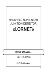
Defective components are not only unreliable; they
are also non-linear due to the altered and unstable
current density caused by the defects.
A measurements of the distortion generated in the
component when a pure sine wave current flows
through it evaluates the reliability due to the correlation's between the non-linearity and the reliability.
The non-linearly - taken as the ratio between the
dominant third harmonic and the applied fundamental voltage - is expressed in
dB. The non-linearity is recognised as are liability parameter just as the noise
index of the component. A noise index
measurement, however, is time consuming and therefore not suited for 100%
testing.
A component is classified as less reliable when its non-linearity is significantly
higher than the median non-linearity of the batch in question.
In production testing, a fixed rejection limit, such as a non-linearly between
-90 to -130 dB, is normally used. Rejection of these dubious components improves the total reliability of the batch. The rejected components also enable
the manufacturer to improve his production technique, thereby gaining higher
reliability and a superior product
Component defects
Typical defects of resistors causing non-linearity.
•
Poor contact between lead and cap
•
Poor contact between cap and resistor material
•
Poor material quality (such as film)
•
In-homogeneous spots in material
•
Defective spiralling
•
Traces of film left in grooves
Typical defects of capacitors causing non-linearity:
•
Poor Contact between electrode and terminal
•
Contamination of dielectric such as iron oxide or iron particles in mica,
paper, polystyrene, etc.
•
Mechanical instability such as movements due to electrostatic forces
•
Poor ceramic quality
•
Longitudinal grooves in ceramic
The defects have the introduction of non-linearly in the component in common.
User-friendly interface
The CLT10 Control Unit has a built-in table as defined in the lEC 440
recommended operating conditions.
The coloured numeric calculator buttons make it very easy to set up the
equipment to measure any given impedance just by entering its standard
lEC colour code.
Furthermore, up to 99 user-defined operating conditions can be stored using the keys or by remote control. This enables the user to specify, Store.
and later re-call specific component-dependent measurement conditions.
System integration
The CLT10 Control Unit has a standard IEEE 448 (GPIB) and an optional
RS232C remote interface controller build in. These interfaces ensure system integration on production lines and in laboratories.
All functions are software-controlled except power on/off. In addition to the
functions controlled from the front panel of the Control Unit, several enhanced features are controllable using the remote interface.
These include instrument identity; integrated system tests; inspection of setups; IEC 440 standard setup plus 1/16, 1/2 1, 2 and 4 W settings and reading of the last 99 measurements
These features enable the user to collect measurement data such as production batch documentation and statistical! analysis for later processing.
Flexible configuration
The power capacity up to 4VA of the CLT20 makes it possible to overload devices being
tested for a short period. This is use-ful for stressing the device before testing under recommended condi-tions, thus ensuring an extended dynamic range of the measurement.
The system includes distortion thre-shold limits for High and Low condi-tions. These fully
programmable limits control the user accessible connector outputs for use on auto-matic go/
no-go production lines.
Remote control of the equipment for system integration and for data col-lection is ensured
by the standard built-in IEEE 488 and RS232C in-terfaces.
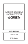
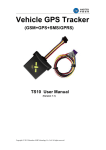
Measuring principle
The measuring method of the CLT20 Component Linearity Test Equipment is based on determina-tion of the non-linearity of normally linear components. A very pure 10 kHz sine wave
voltage is fed to the component under test as shown in Fig. 2.
If the impedance of the component is not absolutely independent of the applied voltage, the
sine wave will be distorted and the current will con-sist of a pure, fundamental sine wave
component and its higher har-monics.
The third harmonic component is normally the dominant one and is chosen as a measure of
the distor-tion - the non-linearity - of the com-ponent.
The third harmonic current is equi-valent to a no-load voltage U3,0 in series with the component under test, which has an impedance ZX. As the 10 kHz low-pass filter blocks the 30 kHz,
the third harmonic voltage U3 is measured over the load impedance R1.
Given the values of ZX and R1, the no-load voltage can easily be found as:
⎛
Z ⎞
U 3, 0 = U 3 ⋅ ⎜⎜1 + x ⎟⎟
R1 ⎠
⎝
By inserting a special low-distortion matching transformer, the compo-nent under test can be
matched to the generator and the 30 kHz volt-meter over a wide impedance range.
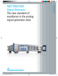
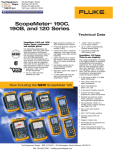
When measuring on a batch of components which have the same nomi-nal
impedance value, the third har-monic value is found to be dis-tributed around
a mean value. The distribution curve is usually a Gaus-sian distribution curve
as shown in Fig. 3.
A few components may, however, exhibit a higher distortion than that of the
rest of the batch. This may be due to small defects or to deviations in the material composition.
Some components contain ma-terials which have a high inherent distortion:
magnetic materials; com-position resistors; high-dielectric ca-pacitors. In these
components, the excessive distortion from small de-fects is concealed in high
inherent distortion and cannot readily be de-tected.
At the other end of the scale there are metal film resistors in which the inherent distortion is very low, typi-cally -130 dB or lower. With these components,
defects cause distor-tion, which normally exceeds that of the rest of the batch
significantly.
What makes the CLT20 Compo-nent Linearity Test Equipment so unique is its
ability to measure dis-tortion as low as 160 dB below the level of the applied
sine wave.
No other commercially available in-strument can even come close to this incredible level of sensitivity, and only with the CLT20 is it possible to detect failures in today's precision resistors.
Inputs/Outputs (rear)
Specifications:
Type of connector
CLT10 Component Linearity Tester
Measuring Unit
Main Specification
Generator frequency
Voltmeter frequency
Voltmeter bandwidth
Measuring speed
Inputs
Min. 10 kHz level setting
10 kHz voltage off
External trigger
Component Range
General
excl. handling. Specifications are
10 kHz current
0 to 10 V for 0 to 200 mA
valid for ³ 14 ms cycle with broad
30 kHz voltage
0 to 10 V for 0 to 100%
Control Outputs
nents per second*)
±1 dB or 5% + 1 digit
Impedance range
Accept, go
Reject, high & low
10kHz voltage on
Data Ready (DRDY)
Measurement End (ME)
All passive impedances.
Primarily impedances within
100W to 3 MW. Restrictions for
<500 ms
106 operations
<300W
Transformation ratio
Input impedance
Max. power
1:1
100W ±2%
0.2 VA @ ZX ³ 10 W
Communication with
Control Unit
Type of connector
Type of interface
Safety Link
Terminals (front)
Measuring terminals
Two binding posts accept stand-ard-size 4 mm banana plugs
4 VA @ ZX ³ 200 W
General
Max. 10 kHz voltage
36 Vrms
RNL @ 0.25 VA
-150 dB, typical -160 dB
Temperature
Operating temperature
Storage temperature
Max. 10 kHz voltage
RNL @ 0.25 VA
1:1
1 kW ±2%
3 VA, 4 VA @ ZX £ 2.5 kW
100 Vrms
-160dB
1:10
10 kW ±2%
1 VA @ ZX ³ 5 kW
4 VA @ ZX ³ 25 kW
360 Vrms
-150 dB, typical -160 dB
Open collector
Open collector
Open collector
Open collector
TTL compatible
TTL compatible
Fiber Optic Link
2 Mbit/s serial, bi-phase
modulation
Contact closure
1 VA @ ZX ³ 50 W
(30 to 300W load)
0 to 10 V for 0 to 100%
within actual range
within actual range
typically more than 30 compo-
Range switching time
Range switching life
3 kW - 30 kW
Transformation ratio
Input impedance
Max. power
Contact closure
Contact closure
Outputs
10 kHz voltage
other ranges exist
300 W - 3 kW
Transformation ratio
Input impedance
Max. power
Max. 10 kHz voltage
RNL @ 0.25 VA
0 to 10 V for 0 to 100% voltage
output within range
10kHz ±2 Hz
30 kHz
400 or 75 Hz selectable
Measuring cycle down to 10 ms
voltmeter bandwidth. Test rate
Accuracy
25-pole, sub-D, female
Relative humidity
Line voltage
5° to 45° C (41° to 113° F)
- 40° to 70° C ( - 40° to 158° F)
Frequency
Power consumption
20 to 80%, non-condensing
90 to 111 V AC,
105 to 130 V AC,
180 to 222 V AC,
210 to 260 V AC
47.5 to 63 Hz
100 VA
Dimensions and Weight
Height
Width
Depth
Net weight
Shipping weight
178 mm (6.9")
483 mm (19.0")
442 mm (17.0")
18 kg (40 lbs)
25 kg (55 lbs)
Ordering Information
30 kW - 3 MW
Transformation ratio
Input impedance
Max. power
Max. 10 kHz voltage
RNL @ 0.25 VA
1:10
100 kW ±2%
4 VA @ ZX £ 250 kW
1 VA @ ZX £ 1 MW
0.25VA @ ZX < 3 MW
1000 Vrms
-140dB, typical -150 dB
@ ZX £ 300 kW
Code
391-081
Description
CLT 10 Measuring Unit
Accessories
983-436
983-437
900-215
906-362
Service Manual
Operator Manual
Measuring cable
Control Unit connector cable, 1m
-130dB @ ZX £3 MW
618-101
Control Unit connector cable, 5m
*) Guideline only; depends on handling
Specifications for CLT20:
Inputs/Outputs (rear)
Type of connector
CLT20 Component Linearity Tester
10 kHz voltage off
External trigger
Main Specification
Generator frequency
Voltmeter frequency
Voltmeter bandwidth
Measuring speed
Accuracy
Component Range
General
10kHz ±2 Hz
30 kHz
400 or 75 Hz selectable
Measuring cycle down to 10 ms
excl. handling. Specifications are
valid for ³ 14 ms cycle with broad
voltmeter bandwidth. Test rate
typically more than 30 components per second*)
±1 dB or 5% + 1 digit
All passive impedances.
Primarily impedances:
CLT10 & CLT20 <100W - 3
MW.
CLT20 down to 10mW
Range switching time
Range switching life
<500 ms
106 operations
Low impedance range
Imput impedance
3mΩ - 3Ω
3Ω - 10Ω
10Ω - 300W
1Ω
Transformation ratio 31,6 : 1
Transformation ratio 31,6 : 1
Transformation ratio 1:1
Input impedance
Max. power
Inputs
Min. 10 kHz level setting
100W ±2%
0.2 VA @ ZX ³ 10 W
1 VA @ ZX ³ 50 W
4 VA @ ZX ³ 200 W
Max. 10 kHz voltage
36 Vrms
RNL @ 0.25 VA
-150 dB, typical -160 dB
(30 to 300W load)
Outputs
10 kHz voltage
10 kHz current
30 kHz voltage
3 kW - 30 kW
Input impedance
Transformation ratio
Max. power
Max. 10 kHz voltage
RNL @ 0.25 VA
30 kW - 3 MW
Input impedance
Transformation ratio
Max. power
Max. 10 kHz voltage
RNL @ 0.25 VA
1 kW ±2%
1:1
3 VA, 4 VA @ ZX £ 2.5 kW
100 Vrms
-160dB
10 kW ±2%
1:10
1 VA @ ZX ³ 5 kW
4 VA @ ZX ³ 25 kW
360 Vrms
-150 dB, typical -160 dB
100 kW ±2%
1:10
4 VA @ ZX £ 250 kW
1 VA @ ZX £ 1 MW
0.25VA @ ZX < 3 MW
1000 Vrms
-140dB, typical -150 dB
@ ZX £ 300 kW
-130dB @ ZX £3 MW
*) Guideline only; depends on handling
Data subject to change
0 to 10 V for 0 to 100% voltage
output within range
Contact closure
Contact closure
0 to 10 V for 0 to 100%
within actual range
0 to 10 V for 0 to 200 mA
0 to 10 V for 0 to 100%
within actual range
Control Outputs
Impedance range
Accept, go
Reject, high & low
10kHz voltage on
Data Ready (DRDY)
Measurement End (ME)
Open collector
Open collector
Open collector
Open collector
TTL compatible
TTL compatible
Communication with
Control Unit
Type of connector
Type of interface
Fiber Optic Link
2 Mbit/s serial, bi-phase
modulation
Safety Link
Contact closure
Terminals (front)
Measuring terminals
4-terminal ERA Lemo
connector
General
Temperature
Operating temperature
Storage temperature
Relative humidity
Line voltage
High impedance range
300 W - 3 kW
Input impedance
Transformation ratio
Max. power
Max. 10 kHz voltage
RNL @ 0.25 VA
25-pole, sub-D, female
Frequency
Power consumption
5° to 45° C (41° to 113° F)
- 40° to 70° C ( - 40° to 158° F)
20 to 80%, non-condensing
90 to 111 V AC,
105 to 130 V AC,
180 to 222 V AC,
210 to 260 V AC
47.5 to 63 Hz
100 VA
Dimensions and Weight for a complete test system
Height
Width
Depth
356 mm (")
483 mm (19.0")
442 mm (17.0")
Net weight complete system
Shipping weight complete syst.
CLT20 28 kg (62 lbs)
CLT20 34 kg (75 lbs)
Ordering Information
Codes for a complete set
Description
73466
CLT20, 3-Harmonic Index Tester
Accessories
983434
983437
86820
51014
Service Manual CU & MU
Operator Manual
Measuring cable, 1m CLT20
IEEE cable 2m, CE approved
Specifications:
CLT10/20 Control Unit
Main Specifications
RS232C Interface
Connector type
Baud rate
Duplex
Parity
Stop bits
Data bits
General
Displays
2 x 4 digits 7 segment green
LED
Annunciation LEDs
10 kHz functions
Four ZX ranges
10 kHz voltage on/off
Temperature
Operating temperature
Storage temperature
Voltage step and entry
Relative humidity
Timer step and entry
IEC 440 entry extended to
E192
standard series
30 kHz functions
Memory
Other functions
Remote Programming
and
Operation
Functions controlled
Read-out in V or dB
Manual and auto range
Programmable reject limit
high
and low
99 setup entries, 99 measure
-ment
storage
IEEE bus setup incl. force to
local RS-232 serial setup
All except mains power on/
off
90 to 130 V AC,
Frequency
Power consumption
200 to 260 V AC
47.5 to 63 Hz
20 VA
Dimensions and Weight
Height for CU for CLT10,
CLT20
Width
Depth
Net weight
Shipping weight
Measurement Unit
Type of connector
Type of interface
Fiber Optic Link
2 Mbit/s serial, bi-phase
modulation
Accessories
983434
983437
933350
24-pole, Champ
933350
Interface functions
SH1, AH1, T6, TE0, L4, LE0,
SR1,
RL1, PP1, DC1, DT0, C0, E2
Setups
Include IEC 440 publication
setups extended to E192
stand-ard
series and 99 memory entries
89 mm (3.5")
483 mm (19.0")
442 mm (17")
5 kg (12 lbs)
9 kg (20 lbs)
Ordering Information
Communication with
IEEE 488 Interface
Type of connector
5° to 45° C (41° to 113° F)
- 40° to 70° C ( - 40° to
158° F)
20 to 80%, noncondensing
Line voltage
Code
Inputs/Outputs (rear)
9-pole, Sub-D, female
300 to 19200
Full
Even, odd or none
1 or 2
7 or 8
Description
CLT 20 Control Unit
Service Manual
Operator Manual
Desktop 19" Rack Enclosure for
CLT10 (CU and MU)
Desktop 19" Rack Enclosure for
CLT20 (CU, MU and LU)
Data subject to change
Danbridge A/S · Lykkegaardsvej 15 · DK-4000 Roskilde · Denmark · www.danbridge.com