1
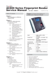
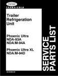
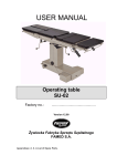
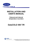
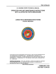
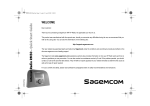
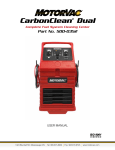
R
Transport Air Conditioning
4
3
2
1
INSTALLATION, OPERATION,
SERVICE & PARTS SUPPLEMENT
for
Rooftop Energy Storage Systems (ESS)
AIR COOLING UNIT
77--62186--00 THRU --04
&
77--62203--00
T--333 Rev--D Change 08/08
INSTALLATION
OPERATION,SERVICE
& SERVICE PARTS
SUPPLEMENT
For
ROOFTOP
ENERGY STORAGE SYSTEM (ESS)
AIR COOLING UNIT
77--62186--00 Thru 77--62186--04
&
77--62203--00
TABLE OF CONTENTS
PARAGRAPH NUMBER
Page
INSTALLATION . . . . . . . . . . . . . . . . . . . . . . . . . . . . . . . . . . . . . . . . . . . . . . . . . . . . . . . . . . . . . . . . . . . . . . . . . . . . . . .
1--1
1.1 Introduction . . . . . . . . . . . . . . . . . . . . . . . . . . . . . . . . . . . . . . . . . . . . . . . . . . . . . . . . . . . . . . . . . . . . . . . . . .
1--1
1.2 Electrical . . . . . . . . . . . . . . . . . . . . . . . . . . . . . . . . . . . . . . . . . . . . . . . . . . . . . . . . . . . . . . . . . . . . . . . . . . . .
1--1
1.3 Installation . . . . . . . . . . . . . . . . . . . . . . . . . . . . . . . . . . . . . . . . . . . . . . . . . . . . . . . . . . . . . . . . . . . . . . . . . . .
1--3
OPERATION & SERVICE . . . . . . . . . . . . . . . . . . . . . . . . . . . . . . . . . . . . . . . . . . . . . . . . . . . . . . . . . . . . . . . . . . . . . .
2-1
2.1 OPERATION . . . . . . . . . . . . . . . . . . . . . . . . . . . . . . . . . . . . . . . . . . . . . . . . . . . . . . . . . . . . . . . . . . . . . . . . .
2-1
2.1.1 Air Circulation . . . . . . . . . . . . . . . . . . . . . . . . . . . . . . . . . . . . . . . . . . . . . . . . . . . . . . . . . . . . . . . . . . . . .
2-1
2.1.2 Refrigerant Cycle . . . . . . . . . . . . . . . . . . . . . . . . . . . . . . . . . . . . . . . . . . . . . . . . . . . . . . . . . . . . . . . . . .
2-1
2.2 MAINTENANCE SCHEDULE . . . . . . . . . . . . . . . . . . . . . . . . . . . . . . . . . . . . . . . . . . . . . . . . . . . . . . . . . . .
2-2
2.2.1 Scheduled Maintenance . . . . . . . . . . . . . . . . . . . . . . . . . . . . . . . . . . . . . . . . . . . . . . . . . . . . . . . . . . . .
2-2
2.3 REFRIGERANT LEAK CHECK . . . . . . . . . . . . . . . . . . . . . . . . . . . . . . . . . . . . . . . . . . . . . . . . . . . . . . . . .
2-2
2.4 EVACUATION AND DEHYDRATION . . . . . . . . . . . . . . . . . . . . . . . . . . . . . . . . . . . . . . . . . . . . . . . . . . . .
2-2
2.5 ADDING REFRIGERANT TO SYSTEM . . . . . . . . . . . . . . . . . . . . . . . . . . . . . . . . . . . . . . . . . . . . . . . . . .
2-2
2.6 SERVICING THE LIQUID LINE SOLENOID VALVE . . . . . . . . . . . . . . . . . . . . . . . . . . . . . . . . . . . . . . .
2-2
2.6.1 Coil Replacement . . . . . . . . . . . . . . . . . . . . . . . . . . . . . . . . . . . . . . . . . . . . . . . . . . . . . . . . . . . . . . . . .
2-2
2.6.2 Internal Part Replacement . . . . . . . . . . . . . . . . . . . . . . . . . . . . . . . . . . . . . . . . . . . . . . . . . . . . . . . . . .
2-2
2.6.3 Replace Entire Valve . . . . . . . . . . . . . . . . . . . . . . . . . . . . . . . . . . . . . . . . . . . . . . . . . . . . . . . . . . . . . .
2-3
2.7 THERMOSTATIC EXPANSION VALVE (Block) . . . . . . . . . . . . . . . . . . . . . . . . . . . . . . . . . . . . . . . . . . .
2-3
2.7.1 Valve Replacement . . . . . . . . . . . . . . . . . . . . . . . . . . . . . . . . . . . . . . . . . . . . . . . . . . . . . . . . . . . . . . . .
2-3
2.8 COIL FREEZE THERMOSTAT (Freeze--Stat) . . . . . . . . . . . . . . . . . . . . . . . . . . . . . . . . . . . . . . . . . . . .
2-3
2.9 HIGH PRESSURE SWITCH (Optional) . . . . . . . . . . . . . . . . . . . . . . . . . . . . . . . . . . . . . . . . . . . . . . . . . .
2-3
SERVICE PARTS . . . . . . . . . . . . . . . . . . . . . . . . . . . . . . . . . . . . . . . . . . . . . . . . . . . . . . . . . . . . . . . . . . . . . . . . . . . . .
3--1
INTRODUCTION . . . . . . . . . . . . . . . . . . . . . . . . . . . . . . . . . . . . . . . . . . . . . . . . . . . . . . . . . . . . . . . . . . . . . . . . . . .
3--1
CONFIGURATION IDENTIFICATION . . . . . . . . . . . . . . . . . . . . . . . . . . . . . . . . . . . . . . . . . . . . . . . . . . . . . . . . .
3--1
MODEL CHART . . . . . . . . . . . . . . . . . . . . . . . . . . . . . . . . . . . . . . . . . . . . . . . . . . . . . . . . . . . . . . . . . . . . . . . . . . . .
3--1
GENERAL NOTES . . . . . . . . . . . . . . . . . . . . . . . . . . . . . . . . . . . . . . . . . . . . . . . . . . . . . . . . . . . . . . . . . . . . . . . . .
3--1
3.1 ESS COOLING SYSTEM 12/24V - COMMON PARTS - 77-62186-00 THRU -04 . . . . . . . . . . . . .
3--2
3.2 ESS COOLING SYSTEM 12/24V MIO CONNECTIONS - 77-62186-00 AND -01 . . . . . . . . . . . . .
3--4
3.3 ESS COOLING SYSTEM 12/24V ORS CONNECTIONS - 77-62186-02, -03 AND -04 . . . . . . . .
3--5
3.4 ESS COOLING SYSTEM - HARNESS 77-62186-00 THROUGH -03 . . . . . . . . . . . . . . . . . . . . . . .
3--6
3.5 ESS COOLING SYSTEM - HARNESS 77-62186-04 . . . . . . . . . . . . . . . . . . . . . . . . . . . . . . . . . . . . .
3--6
3.6 ESS COOLING SYSTEM - 24V ORS CONNECTIONS (MCI) -- 77--62203--00 . . . . . . . . . . . . . . . .
3--7
3.6 ESS COOLING SYSTEM - 24V ORS CONNECTIONS (MCI) -- 77--62203--00 . . . . . . . . . . . . . . . .
3--8
3.7 ESS COOLING SYSTEM - SUCTION TUBE ASSEMBLY FOR 77-62203-00 . . . . . . . . . . . . . . . . . 3--10
3.8 ESS COOLING SYSTEM - LIQUID TUBE ASSEMBLY FOR 77-62203-00 . . . . . . . . . . . . . . . . . . . . 3--10
3.9 ESS COOLING SYSTEM - HARNESS FOR 77-62203-00 (MCI) . . . . . . . . . . . . . . . . . . . . . . . . . . . . 3--11
LIST OF FIGURES
Figure 1-1 ESS Air Cooler & Components . . . . . . . . . . . . . . . . . . . . . . . . . . . . . . . . . . . . . . . . . . . . . . . . . . . . . . .
1--1
Figure 1-2 Electrical Schematic (ESS Air Cooler W/Micromax) Rooftop (RF) Application . . . . . . . . . . . . . . .
1--1
Figure 1-3 Electrical Schematic (ESS Air Cooler W/Micromax) Rearmount (RM55) Application . . . . . . . . . .
1--2
Figure 1-4 Electrical Schematic (ESS Air Cooler W/Micromax) Rearmount (RM50) Application . . . . . . . . . .
1--2
Figure 1-5 ESS With Air Cooler Installed . . . . . . . . . . . . . . . . . . . . . . . . . . . . . . . . . . . . . . . . . . . . . . . . . . . . . . . .
1--3
Figure 2-1 Air Cooler Operation . . . . . . . . . . . . . . . . . . . . . . . . . . . . . . . . . . . . . . . . . . . . . . . . . . . . . . . . . . . . . . . .
2-1
Figure 2-2 Air Cooler Refrigerant Flow Diagram . . . . . . . . . . . . . . . . . . . . . . . . . . . . . . . . . . . . . . . . . . . . . . . . . .
2-2
Figure 2-3 Liquid Line Solenoid Valve . . . . . . . . . . . . . . . . . . . . . . . . . . . . . . . . . . . . . . . . . . . . . . . . . . . . . . . . . . .
2-3
i
T--333
SECTION 1
INSTALLATION
conjunction with a Carrier Rooftop (RF) or Rear
Mounted (RM) main air conditioning system and a
Micromax Controller. The purpose of the air cooler is to
aid in keeping the hybrid bus battery pack (ESS) cool.
The ESS has its own fans that provide airflow
(ventilation system). The Carrier ESS Air Cooler is
integrated into that ventilation system.
1.1 Introduction
The Carrier Rooftop ESS (Energy Storage System) Air
Cooling Unit (See Figure 1-1) is a one piece assembly
consisting of an evaporator coil, expansion valve (TXV),
liquid line, solenoid valve, suction line and a freeze
thermostat. The ESS Air Cooling Unit is used in
Solenoid
Valve
RETURN
AIR
LIQUID
SUCTION
COOL
AIR
Coil
Drain Tubes
AMBIENT AIR
TXV
Freeze Thermostat
Coil
Figure 1-1 ESS Air Cooler & Components
1.2 Electrical
Movement of refrigerant through the Carrier Air Coolling
Unit is controlled by the electrical system of the main air
conditioning system (See Figure 1-2, Figure 1-3 or
Figure 1-4).
The internal components of the ESS along with the
Carrier Air Cooling Unit must have sufficient air
movement to keep the ESS temperature under 30° C
(86° F).
Note
The Air Cooler will not operate unless the main
evaporator assembly is in the cool mode.
Reference Unit 68RF353-101-7
From main system
OPEN P-RISE 300±10
CLOSE P-DROP 200±10
K13
30
HPS
JA
4
17
87
C1J
CL
A
B
Compressor
D51
Liquid Solenoid Valve
In Evaporator RF
A
OUT
FT
LSV
B
JA
33
-
Ground
Stud
-
PTB2
IN
LEGEND
K13 - CLUTCH RELAY
TB - TERMINAL BOARD
CL - ClLUTCH
LSV - LIQUID LINE SOLENOID
FT - FREEZE THERMOSTAT
A
LSV
B
Liquid Solenoid Valve ESS Air Cooler
ESS AIR COOLING UNIT
Figure 1-2 Electrical Schematic (ESS Air Cooler W/Micromax) Rooftop (RF) Application
1--1
T-333
Reference Unit 68RM55-101-11
From main system
OPEN P-RISE 300±10
CLOSE P-DROP 200±10
K13
30
JP4
2
87
HPS
L
CL
A
B
D51
M
OUT
GRD
A
FT
B
LSV
A
GRD
JP4
5
GRD
B
IN
LEGEND
K13 - CLUTCH RELAY
TB - TERMINAL BOARD
A
CL - CLUTCH
LSV
B
Liquid Solenoid Valve ESS Air Cooler
LSV - LIQUID LINE SOLENOID
ESS AIR COOLING UNIT
FT - FREEZE THERMOSTAT
Figure 1-3 Electrical Schematic (ESS Air Cooler W/Micromax) Rearmount (RM55) Application
Reference Unit 68RM50-101-36
ESS COOLER
FTS
A
JP4
K13
2
87
LSV2
B
CL
B
LSV1
B
HPS
A
30
D51
JP4
A
5
GRD
LEGEND
LSV 1 - LIQUID LINE SOLENOID (RM)
LSV 2 - ESS LIQUID LINE SOLENOID
CL - CLUTCH
K13 - CLUTCH RELAY
FTS - FREEZE THERMOSTAT SWITCH
Figure 1-4 Electrical Schematic (ESS Air Cooler W/Micromax) Rearmount (RM50) Application
T-333
1--2
1.3 Installation
To install the air cooler to the ESS do the following:
a. Remove and save six bolts (6M) from the air intake of
the ESS.
b. Remove and discard the intake grill.
c. Remove and save six bolts (6M) from the ESS air outlet.
d. Remove left side panel (side opposite TXV) on the Air
Cooler. This will allow you acces the ESS bolt holes.
e. Place the Air Cooler against the ESS and fix in place
using the original 12 (6M) ESS bolts (See Figure 1-5).
f. Replace Air Cooler side panel.
g. Connect a #6 or #8 liquid hose (MIO or ORS depending on application) from the main evaporator assembly to the Air Cooler TXV.
h. Connect a #10 suction hose (MIO or ORS depending
on application) from the Air Cooler TXV to the system
compressor.
i. Connect wiring from the Liquid Line Solenoid Valve on
the main evaporator assembly to the Air Cooler plug.
TOP VIEW
AIR COOLER
FRONT VIEW
ESS
AIR COOLER
ESS
Figure 1-5 ESS With Air Cooler Installed
1--3
T-333
SECTION 2
OPERATION & SERVICE
WARNING
BE SURE TO OBSERVE ALL WARNINGS AND CAUTIONS LISTED IN THE THIS MANUAL BEFORE
PERFORMING MAINTENANCE ON THE HVAC SYSTEM AND THE AIR COOLER.
WARNING
DO NOT ATTEMPT ANY SERVICE TO THE ENERGY STORAGE SYSTEM. THE ESS CONTAINS HIGH
VOLTAGE AND SERIOUS INJURIES COULD OCCUR. THE CARRIER TRANSPORT AIR COOLER IS
THE ONLY ITEM THAT IS SERVICABLE.
Energy Storage System (ESS). Ambient air is pulled
across the evaporator coil and cooled. Cool air is then
circulated throughout the ESS. The cool air is mixed
with the heat given off from the ESS. The warm air is
ejected from the ESS and returned to the ambient.
2.1 OPERATION
2.1.1 Air Circulation
The Air Cooler has no fan or blower assemblies.
Circulation is achieved from the fans located within the
RETURN TO
AMBIENT
WARM RETURN AIR
ESS
ESS
AMBIENT AIR
COOL AIR
Figure 2-1 Air Cooler Operation
The low pressure, low temperature liquid that flows into
the Air Cooler (evaporator) coil tubes is colder than the
The ESS Air Cooler is an auxillary cooling component of
air that is circulated over the evaporator tubes by the
a rooftop (RF) or rear mounted (RM) air conditioning
ESS fans. Heat transfer is established from the
system. When the main evaporator calls for cooling the
evaporator air (flowing over the tubes) to the refrigerant
liquid line solenoid valve is opened sending a signal to
(flowing inside the tubes). The evaporator tubes have
open the liquid line solenoid valve on the ESS Air Cooler
alunimum fins to increase heat transfer from the air to
(See Figure 2-2).
the refrigerant; therefore the cooler air is circulated to
the interior of the ESS. The liquid line solenoid valve
Liquid refrigerant flows from the main condensing
closes during shutdown to prevent refrigerant flow.
assembly through the ESS Air Cooler liquid line solenoid
valve to the expansion valve (TXV). The thermal
The transfer of heat from the air to the low temperature
expansion valve reduces pressure and temperature of
refrigerant in the evaporator coil causes the liquid to
the liquid and meters the flow of liquid refrigerant to the
vaporize. This low temperature, low pressure vapor
Air Cooler coil to obtain maximum use of the coils heat
passes through the suction line and returns to the
transfer surface.
compressor where the cycle is repeated.
2.1.2 Refrigerant Cycle
2--1
T-333
Liquid Line
Solenoid
ESS Air Cooler
TXV
Liquid From Unit
Mounting Bracket
Fitting Connections
LIQUID
Suction To Compressor
LIQUID VAPOR MIX
VAPOR
Figure 2-2 Air Cooler Refrigerant Flow Diagram
2.2 MAINTENANCE SCHEDULE
2.6 SERVICING THE LIQUID LINE SOLENOID
VALVE
Normal or routine maintenance on the ESS Air Cooler
will normally be performed in conjuction with the main
rooftop (RF) or rear mounted (RM) maintenance
schedules. Refer to the appropriate operation and
service manual for these maintenance schedules.
The Liquid line solenoid valve (Figure 2-3) is very similar
to a heat valve. It requires no maintenance unless a
malfunction to the internal parts or coil occurs. This may
be caused by foreign material such as: dirt, scale, or
sludge in the refrigeration system, or improper voltage
to the coil.
There are only three possible valve malfunctions: coil
burnout, failure to open, or failure to close.
Coil burnout may be caused by the following:
1 Improper voltage.
2 Continuous over-voltage, more than 10% or undervoltage of more than 15%.
3 Incomplete magnet circuit due to the omission of the
coil hosing or plunger.
4 Mechanical interface with movement of plunger
which may be caused by a deformed enclosing tube.
Failure to open may be caused by the following:
1 Coil burned out or an open circuit to coil connections.
2 Improper voltage.
3 Defective plunger or deformed valve body assembly.
Failure to close may be caused by the following:
2.2.1 Scheduled Maintenance
a. Check inlet air filters weekly. Clean or replace as
necessary.
b. Check operation of the liquid line solenoid. It must
operate in conjuction with the rooftop or rear mount
evaporator liquid line solenoid (Refer to paragraph
2.6).
c. Check liquid & suction line connections for leaks.
d. Check and clean Air Cooler coil as necessary.
2.3 REFRIGERANT LEAK CHECK
A refrigerant leak check should always be performed
after the system has been opened to replace or repair a
component.
To check for leaks in the refrigeration system, perform
the following procedure:
a. Ensure liquid line solenoid valve is open. Solenoid
valve will need to be powered from the closest 12VDC
or 24VDC source.
1 Defective plunger or deformed valve body assembly.
2 Foreign material in the valve.
Refer to the Rooftop (RF) or rear mounted (RM) service
manual for procedures.
2.6.1 Coil Replacement
a. It is not necessary to remove the refrigerant charge
from the system.
b. Disconnect Air Cooler from Rooftop or Rear Mounted
evaporator assembly.
c. Disconnect wire leads to coil.
d. Remove coil retaining clip and nameplate.
e. Lift failed coil from enclosing tube and replace.
f. Connect wire leads, connect to main evaporator and
test operation.
2.6.2 Internal Part Replacement
2.4 EVACUATION AND DEHYDRATION
The presence of moisture in a refrigeration system can
have many undesirable effects. The most common are
copper plating, acid sludge formation, “freezing-up” of
metering devices by free water, and formation of acids,
resulting in metal corrosion.
a. Evacuate and dehydrate only after pressure leak test.
Refer to the Rooftop (RF) or rear mounted (RM) service
manual for procedures.
a. Disconnect system from bus battery.
b. Recover and recycle system refrigerant. Refer to the
Rooftop (RF) or rear mounted (RM) service manual
for procedures.
2.5 ADDING REFRIGERANT TO SYSTEM
Refer to the Rooftop (RF) or rear mounted (RM) service
manual for procedures.
T-333
2--2
c. Assemble valve and leak check.
2.7.1 Valve Replacement
a. Recover and recycle system refrigerant. Refer to the
Rooftop (RF) or rear mounted (RM) service manual
for procedures.
d. Evacuate and recharge system. Refer to the Rooftop
(RF) or rear mounted (RM) service manual for procedures.
b. Remove no--drip insulating tape from block valve and
fitting connections.
c. Carefully loosen all fittings connected to the block
valve.
2.6.3 Replace Entire Valve
a. Recover and recycle system refrigerant. Refer to the
Rooftop (RF) or rear mounted (RM) service manual
for procedures.
b. Remove valve assembly from bracket.
CAUTION
c. Disconnect wire leads to coil.
d. Disassemble new valve, to protect internal parts, and
solder to lines.
e. Assemble and leak check valve. Refer to the Rooftop
(RF) or rear mounted (RM) service manual for procedures.
There may be liquid refrigerant trapped behind the block valve. Slowly loosen the fittings and avoid contact with exposed skin
or eyes.
f. Evacuate and recharge.system. Refer to the Rooftop
(RF) or rear mounted (RM) service manual for procedures.
d. Remove and replace block valve, lubricating the fitting threads and O--rings with mineral oil before torquing to the required specification of 30/35 Ft./Lb.
g. Connect wire leads and test operation.
NOTE
Do not attempt to adjust the replacement block
valve. The valves are preset at the factory.
1
2
e. Insulate block valve with no--drip insulating tape.
f. Leak check, evacuate and charge system with recovered refrigerant. Refer to the Rooftop (RF) or rear
mounted (RM) service manual for procedures.
g. Check operation of the system. Adjust refrigerant
charge if needed. Refer to the Rooftop (RF) or rear
mounted (RM) service manual for procedures.
3
4
5
2.8 COIL FREEZE THERMOSTAT (Freeze--Stat)
Freeze Thermostats are used to prevent ice from
forming on the Air Cooler (evaporator) coil, which is an
indication that liquid is getting back to the compressor.
The Air Cooler Freeze--Thermostat is wired in series
with the liquid line solenoid valve. If the
Freeze--Thermostat reaches the preset temperature it
will open, shutting off power to the liquid line solinoid
which will also open stopping the flow of liquid
refrigerant.
6
7
8
1 Snap Cap
2 Coil Assembly
3 Enclosing Tube
Assembly
4 Plunger Assembly
5
6
7
8
Gasket
Piston Assembly
Body
Bracket Adapter
The Freeze--Thermostat will cut--out at 30.5° F (--0.8°
C) ± 1.5° F, and it will cut--in at 45° F (7.2 ° C) ±1.5 ° F.
Preset at the factory (Non--Adjustable).
In order to accurately sense the temperature of the
refrigerant within the evaporator tubes the probe of the
Freeze--Thermostat must always be inserted within the
evaporator coil.
Figure 2-3 Liquid Line Solenoid Valve
2.7 THERMOSTATIC EXPANSION VALVE (Block)
The thermostat expansion valve is an automatic device
which maintains constant superheat of the refrigerant
gas leaving the evaporator regardless of suction
pressure. The valve functions are: (a) automatic control
of refrigerant flow to match the evaporator (Air Cooler)
load and (b) prevention of liquid refrigerant entering the
compressor. Unless the valve is defective, it seldom
requires any maintenance.
2.9 HIGH PRESSURE SWITCH (Optional)
The ESS Air Cooler/Rooftop System has a normally
closed High Pressure Switch wired in series with the
Micromax Controller. The HPS will open when the
refrigerant pressure rises to 300 Lbs. (±10 lbs.). The
HPS will close when the pressure drops to 200Lbs.
(±10 lbs.).
2--3
T-333
SECTION 3
SERVICE PARTS
INTRODUCTION
This section provides identification of service replacement parts for the Carrier Transport Air Conditioning Energy
Supply System (ESS) Air Cooling Units listed in the following Model Chart.
CONFIGURATION IDENTIFICATION
Unit identification information is provided on a plate (decal) located on the side of the ESS. This plate provides the unit
model number and the unit serial number. The model number identifies the unit configuration and differences in
detailed parts.
MODEL CHART
ESS AIR COOLER
Model Number
Solenoid Coil Voltage (Watts)
Fitting Connections To TXV
77-62186-00
12 VDC - 15 Watts
Male Insert O-Ring (MIO)
77-62186-01
24 VDC - 15 Watts
Male Insert O-Ring (MIO)
77-62186-02
12 VDC - 15 Watts
O-Ring Seal (ORS)
77-62186-03
77-62186-04
77-62203-00
24 VDC - 15 Watts
24 VDC - 15 Watts
24 VDC - 15 Watts
O-Ring Seal (ORS)
O-Ring Seal (ORS)
O-Ring Seal (ORS)
GENERAL NOTES
To find replacement parts, determine major group in which replacement parts are located and turn to the appropriate
page for the illustrated breakdown of the replacement parts. The following letter designations are used to classify parts
throughout this list.
A/R
As Required
N/S
Not Shown on Illustration
NSS
Not Sold Separtely - Order next higer assembly or kit.
P-Suffix P-- added to part number means part is available in packaged quantity only.
PL
Purchase Locally
SST
Stainless Steel - 300 Series unless otherwise specified.
SV
Suffix SV added to part number designates service replacement part.
3--1
T--333
3.1 ESS COOLING SYSTEM 12/24V - COMMON PARTS - 77-62186-00 THRU -04
NOTCH -04
ASSEMBLY ONLY
27,33
39 OR 48, LIQUID/SUCTION
TUBING ASSEMBLY
SEE SECTION 3.2 OR 3.3
28, 29, 32
26, 33, 35
7, 8, 33
20, 21, 22, 23, 24, 34
1, 32, 33
2, 33
25
3, 4, 5,6
14, 15, 16, 36, 37, 38
13
12, 34
9, 10, 11, 34
30
31
19, 34
SERIAL # DECAL
34
18
17
77-62186-00/01 SHOWN
59 OR 66, HARNESS
SEE SECTION 3.4 OR 3.5
T--333
3--2
3.1 ESS COOLING SYSTEM 12/24V - COMMON PARTS - 77-62186-00 THRU -04 (Continued)
Item
Part Number
Description
Qty
1
2
3
4
5
6
67-62003-00
68-63600-00
86-62438-00
42-62123-00
42-62125-00
02-62000-00
Panel Assembly, Interface Control, White
Panel, Painted
Drain Pan Assembly, Painted
Insulation, Baffle, Foam, Adhesive Backed
Baffle, Foam
Adhesive, Hot Melt D/C Tape (150 Feet Roll)
1
1
1
1
1
1
7
8
9
10
11
12
13
14
15
16
67-62002-00
42-62124-00
67-62002-01
42-62124-01
58-00661-04
12-00547-00
AC801-201
68-63624-00
14-00301-03
AC801-202
08-62061-00
Panel Assembly, Side, Interface Control, White
Insulation, Side Panel, Foam, Adhesive Backed
Panel Assembly, Side, Interface Control, White
Insulation, Side Panel, Foam, Adhesive Backed
Bushing, Plastic, 1.00 Inch Diameter Hole
Thermostat, Freeze Up, Non-Adjustable, 12/24 VDC
O-Ring, 3/8 Inch
Bracket, TXV, Painted
Valve, Thermal Expansion, Block Type, R-134a
O-Ring, 1/2 Inch
Coil Assembly, Evaporator, EM-6 - Includes:
1
1
1
1
1
1
1
1
1
2
1
40-01124-00
.....Body, Valve, Schrader, Brass 1/4 SAE Flare - Includes:
1
14-00351-00
..........Core, Valve, Schrader (Nickel Plated)
1
DD19CA061
..........Cap, Seal Flare1/4 Inch
1
38-00573-09
68-63578-00
67-62000-00
22-02567-03
22-02567-02
Filter, Air, .012 Thick X 8.00 X 18.20 Inches
Bracket, Mounting, Air Filter, Painted
Bracket Assembly, Mounting, Solenoid Valve, White
Coil, 12 VDC, 15 Watts (Model 77-62186-00 & -02)
1
2
1
1
Coil, 24 VDC, 15 Watts (Model 77-62186-01, -03 & -04)
1
Connector, Male, 2 Pin, Black
1
86-62440-01
Terminal, Female, (18-20 AWG)
Seal, Cable, Gray
O-Ring, 5/8 Inch
Bracket, Mounting, Tube Connections, Painted (MIO)
2
2
1
1
86-62440-00
Bracket, Mounting, Tube Connections, Painted (ORS)
1
68-63573-00
Panel, Top, Painted (Model 77-62186-00, -01, -02, -03)
1
68-63573-01
Panel, Top, With Notch, Painted (Model 77-62186-04)
1
28
68-63572-00
Panel, Center, Painted
1
29
30
42-62122-00
62-02444-00
Insulation, Center Panel, Foam, Adhesive Backed
Decal, Charge Only With R-134a
1
1
31
AC022-289
Decal, Carrier Oval, 2.88 Inches
1
17
18
19
20
21
22
22-01585-00SK
23
24
25
22-01566-01
22-02394-00
AC801-203
26
27
3--3
T--333
3.1 ESS COOLING SYSTEM 12/24V COMMON PARTS - 77-62186-00 THRU -04 (Continued)
32
42-62126-00
Insulation, Front Panel Assembly, Black, Adhesive Backed
1
33
34-62021-01
Rivet, Blind, Dome Head, 3/16 Dia., Grip Range: .250-.375
15
34
34-00917-18
Screw, Hex Head, Captive Washer, #10-32 X .50 Inch Long
18
35
36
34-00917-12
34-00655-12
Screw, Hex Head, Captive Washer, #10-32 X 3/4 Inch Long
Screw, Cap, Hex Head, 1/4-20 X 1-1/2 Inch Long, SST
2
1
37
38
34-00662-11
34-00667-61
Washer, Flat, 1/4 Inch, SST
Nut, Hex, Self Locking, 1/4-20, SST
1
1
3.2 ESS COOLING SYSTEM 12/24V MIO CONNECTIONS - 77-62186-00 AND -01
42
43
47
46
39
41
40
44
45
39
40
41
42
43
44
81-62142-00
56-62299-00
56-62301-00
40-00090-04
14-00150-14
40-62032-02
45
46
40-62032-01
68-63580-00
Fitting, Swivel Nut, 5/8 X 7/8-14 M.I.O.
Plate, Connection Retainer, Brass (MIO)
1
1
47
56-62300-00
Tube, Liquid, Bent, 1/2 OD X .035 Wall Copper
1
T--333
Tube Assembly, Liquid & Suction (MIO Fittings) - Includes:
Tube Assembly, Liquid, Bent, 3/8 OD X .028 Wall Copper
Tube Assembly Suction, Bent, 5/8 OD X .040 Wall Copper
Reducer, 1/2 ODM X 3/8 ODF, Copper
Valve, Solenoid, Without Coil, 1/2 ODF (N.C.)
Fitting, Swivel Nut, 1/2 X 3/4-16 M.I.O.
3--4
1
1
1
1
1
1
3.3 ESS COOLING SYSTEM 12/24V ORS CONNECTIONS - 77-62186-02, -03 AND -04
51
52
51
56
48
50
49
53, 58
55
54, 57
48
49
50
51
52
53
54
55
56
57
58
81-62143-00
56-62299-00
56-62301-00
40-00090-04
14-00150-14
40-00491-12
40-00491-09
68-63580-00
56-62302-00
42-00243-02
42-00243-03
Tube Assembly, Liquid & Suction (ORS Fittings) - Includes:
Tube Assembly, Liquid, Bent, 3/8 OD X .028 Wall Copper
Tube Assembly Suction, Bent, 5/8 OD X .040 Wall Copper
Reducer, 1/2 ODM X 3/8 ODF, Copper
Valve, Solenoid, Without Coil, 1/2 ODF (N.C.)
Fitting, ORS, 3/8 X 11/16-16 (#6)
Fitting, ORS, 5/8 X 1.00-14 (#10)
Plate, Connection Retainer, Brass (ORS)
Tube, Liquid, Bent, 3/8 OD X .028 Wall Copper
O-Ring, 1.50 I.D. x 1.75 O.D.
O-Ring, 0.62 I.D. x 0.75 O.D.
3--5
1
1
1
2
1
1
1
1
1
1
1
T--333
3.4 ESS COOLING SYSTEM - HARNESS 77-62186-00 THROUGH -03
61,62,63
64
65
60,62,63
59
59
60
61
62
63
64
65
22-62233-00
22-01585-00SK
22-02392-00
22-02393-00
22-02394-01
22-01141-01
58-04730-00F25
Harness, ESS Coiling System - Includes:
.....Connector, Male, 2 Pin, Black (E1)
.....Connector Kit, 2 Pin (C1)
.....Terminal, Male (14-16 AWG)
.....Seal, Cable, Blue
.....Terminal, Female Slip-On, (14-16 AWG) (T1, T2)
.....Tube, Split, 1/4 Inch, Corrugated, Fire Retardent (25 Foot Roll)
1
1
1
4
4
2
1
3.5 ESS COOLING SYSTEM - HARNESS 77-62186-04
70
67, 68, 69
71
67, 68, 69
66
66
67
22-62233-01
22-02392-00
Harness, ESS Coiling System - Includes:
.....Connector Kit, 2 Pin (C1) (E1)
1
2
68
22-02393-00
.....Terminal, Male (14-16 AWG)
4
69
22-02394-01
.....Seal, Cable, Blue
4
70
22-01141-01
.....Terminal, Female, Slip-On, 14 AWG (T1, T2)
2
71
58-04730-00F25
.....Tube, Split, 1/4 Inch, Corrugated, Fire Retardant (25 Feet Roll)
1
T--333
3--6
3.6 ESS COOLING SYSTEM - 24V ORS CONNECTIONS (MCI) -- 77--62203--00
1
3
4
2
3
REF: 77-62203-00 (MCI)
Item
Part Number
Description
1
77-62203-01
ESS Cooling Assembly, Chassis Kit (Reference Only)
1
2
3
67-62021-00
42-62139-00
Bracket Assembly, Interface Control
Insulation, Bracket, Foam, Adhesive Backed
1
2
4
34-01267-20
Screw, Flat Head Socket, M6 x 20MM Long, Grade 10.9
6
3--7
Qty
T--333
3.6 ESS COOLING SYSTEM - 24V ORS CONNECTIONS (MCI) -- 77--62203--00 -- Continued
10, 29, 31
11, 37
12, 35
16
10, 33
3, 20, 22, 23
10, 13, 30
10, 24
25
1
4, 10
5, 26, 36
6, 7, 8, 9
14, 21, 34
14, 19, 27
50
2, 14, 17, 18, 28, 32
Decal, SN
Warranty I.D.
15
REF: 77--62203--01
T--333
3--8
3.6 ESS COOLING SYSTEM - 24V ORS CONNECTIONS (MCI) - 77--62203--00 -- Continued
Item
Part Number
Description
Qty
-
77-62203-01
ESS Cooling Assembly, Chassis Kit (Reference Only) - Includes:
--
1
2
AC022-289
02-62000-00
...Decal, Carrier Oval, 2.88 Inches
...Adhesive, Hot Melt D/C Tape (150 Feet Roll)
1
1
3
08-62079-00
...Coil Assembly, Evaporator, ESS Cooler
1
4
5
12-00547-00
14-00301-03
...Thermostat, Freeze Up, Non-Adjustable, 12/24 VDC
...Valve, Thermal Expansion, Block Type, R-134a
1
1
6
7
22-01566-01
22-01585-00SK
...Terminal, Female (18-20 AWG)
...Connector, Male, 2 Pin, Black
2
1
8
9
22-02394-00
22-02567-02
...Seal, Cable, Gray
...Coil, 24 VDC, 15 Watts
2
1
10
11
34-00917-08
34-06088-04
...Screw, Hex Head, Captive Washer, #10-32 X .50 Inch Long
...Nut, Hex, ORS, 0.625 Tube x 1.00-14 Thread, Zinc
10
1
12
13
34-06088-05
34-06212-15
...Nut, Hex, ORS, 0.035 Tube x 11/16-16 Thread, Zinc
...Washer, Plain, Type A, 7/16, SST
1
1
14
34-62021-01
...Rivet, Blind, Dome Head, 3/16 Dia., Grip Range: .250-.375
22
15
16
16A
17
18
19
20
21
22
23
24
25
26
27
28
38-00573-09
40-01184-00
40-01184-50
42-62125-02
42-62131-05
42-62131-06
42-62131-03
42-62131-07
42-62138-00
42-62138-01
66U1-3882
58-00661-04
62-62039-00
68-63753-00
86-62520-00
...Filter, Air, .012 Thick X 8.00 X 18.20 Inches
...Fitting Assembly, Low Side Adapter, M8 - Includes:
.....O-- Ring
...Baffle, Foam
...Insulation, Foam, Adhesive Backed
...Insulation, Foam, Adhesive Backed
...Insulation, Foam, Adhesive Backed
...Insulation, Foam, Adhesive Backed
...Insulation, Foam, Adhesive Backed
...Insulation, Foam, Adhesive Backed
...Wire Tie, Self --Locking, 7.00 Inches, Black
...Bushing, Plastic, 1.00 Inch Diameter Hole
...Label, Refrigerant, Charge Only With R-134a
...Panel Assembly, Front, Painted
...Drain Pan Assembly, Painted
1
1
1
1
1
1
1
1
1
1
2
1
1
1
1
29
30
68-63759-00
67-62022-00
...Bracket, Tube Connections, Painted
...Bracket Assembly, Support
1
1
31
32
67-62020-00
68-63755-00
...Bracket Assembly, Fitting Support, Tube Connections
...Panel, Painted
1
1
33
34
67-62023-00
68-63752-00
...Bracket Assembly, Support
...Panel, Center, Painted
1
1
35
36
AC801-201
AC801-202
...O-Ring, 3/8 Inch
...O-Ring, 1/2 Inch
1
2
37
AC801-203
...O-Ring, 5/8 Inch
1
3--9
T--333
3.7 ESS COOLING SYSTEM - SUCTION TUBE ASSEMBLY FOR 77-62203-00
40
39
38
41, 42, 43
Item
Part Number
Description
Qty
38
81-62158-00
Tube Assembly, Suction - Includes:
1
39
40
56-62323-00
40-00491-15
...Tube Assembly Suction, Bent, 5/8 OD X .040 Wall Copper
...Fitting, ORS, 5/8 ODF X 1.00-14
1
1
41
42
40-01124-00
14-00351-00
...Body, Valve, Schrader, Brass 1/4 SAE Flare - Includes
.....Core, Access Valve (Nickel Plated)
1
1
43
DD19CA061
.....Cap, Seal, Flare, 1/4 Inch
3.8 ESS COOLING SYSTEM - LIQUID TUBE ASSEMBLY FOR 77-62203-00
45
47
1
49
44
48
Item
Part Number
44
45
46
47
48
49
81-62157-00
56-62321-00
56-62322-00
40-00491-12
14-00150-14
40-00201-02
T--333
49
46
Description
Tube Assembly, Liquid - Includes:
...Tube, Liquid, Bent, 3/8 OD X .028 Wall Copper
...Tube Assembly, Liquid, Bent, 3/8 OD X .028 Wall Copper
...Fitting, ORS, 3/8 x 11/16-16
...Valve, Solenoid, Without Coil, 1/2 ODF (N.C.)
...Bushing, Tube, Flush, 1/2 ODM x 3/8 ODS
3--10
Qty
1
1
1
1
1
2
3.9 ESS COOLING SYSTEM - HARNESS FOR 77-62203-00 (MCI)
54
51, 52, 53
55
51, 52, 53
50
50
51
52
53
54
55
22-62233-01
22-02392-00
22-02393-00
22-02394-01
22-01141-01
58-04730-00F25
Change 08/08
Harness, ESS Coiling System - Includes:
.....Connector Kit, 2 Pin (C1)
.....Terminal, Male (14-16 AWG)
.....Seal, Cable, Blue
.....Terminal, Female Slip-On, (14-16 AWG) (T1, T2)
.....Tube, Split, 1/4 Inch, Corrugated, Fire Retardent (25 Foot Roll)
3--11
1
2
4
4
2
1
T--333
INDEX
Text Index
M
A
ADDING REFRIGERANT TO SYSTEM , 2-2
Maintenance Schedule, 2-2
Air Circulation, 2-1
C
COIL FREEZE THERMOSTAT, 2-3
O
OPERATION, 2-1
Coil Replacement, 2-2
E
R
Refrigerant Cycle, 2-1
Electrical, 1-1
REFRIGERANT LEAK CHECK , 2-2
EVACUATION AND DEHYDRATION , 2-2
Replace Entire Valve, 2-3
H
HIGH PRESSURE SWITCH, 2-3
I
S
Scheduled Maintenance, 2-2
SERVICE, 2-1
T
Installation, 1-3
Internal Part Replacement, 2-2
Introduction, 1-1
Thermostatic Expansion Valve, 2-3
V
L
Liquid Line Solenoid, 2-2
Valve Replacement, 2-3
Index--1
T--333
INDEX
Part Number Index
PART NO.
PAGE NO.
PART NO.
PAGE NO.
02-62000-00,
3-3, 3-9
40-01184-50,
3-9
08-62061-00,
3-3
40-62032-01,
3-4
08-62075-00,
3-9
40-62032-02,
3-4
12-00547-00,
3-3, 3-9
42-00243-02,
3-5
14-00150-14,
3-4, 3-5, 3-10
42-00243-03,
3-5
14-00301-03,
3-3, 3-9
42-62122-00,
3-3
14-00351-00,
3-3, 3-10
42-62123-00,
3-3
22-01141-01,
3-6, 3-11
42-62124-00,
3-3
22-01566-01,
3-3, 3-9
42-62124-01,
3-3
22-01585-00SK,
3-3, 3-6, 3-9
42-62125-00,
3-3
22-02392-00,
3-6, 3-11
42-62125-02,
3-9
22-02393-00,
3-6, 3-11
42-62126-00,
3-4
22-02394-00,
3-3, 3-9
42-62131-03,
3-9
22-02394-01,
3-6, 3-11
42-62131-05,
3-9
22-02567-02,
3-3, 3-9
42-62131-06,
3-9
22-02567-03,
3-3
42-62131-07,
3-9
22-62233-00,
3-6
42-62138-00,
3-9
22-62233-01,
3-11
42-62138-01,
3-9
34-00655-12,
3-4
42-62139-00,
3-7
34-00662-11,
3-4
56-62299-00,
3-4, 3-5
34-00667-61,
3-4
56-62300-00,
3-4
34-00917-08,
3-9
56-62301-00,
3-4, 3-5
34-00917-12,
3-4
56-62302-00,
3-5
34-00917-18,
3-4
56-62321-00,
3-10
34-01267-20,
3-7
56-62323-00,
3-10
34-06088-04,
3-9
58-00661-04,
3-3, 3-9
34-06088-05,
3-9
58-04730-00F25,
3-6, 3-11
62-02444-00,
3-3
34-06212-15,
3-9
62-62039-00,
3-9
34-62021-01,
3-4, 3-9
66U1-3882,
3-9
38-00573-09,
3-3, 3-9
67-62000-00,
3-3
40-00090-04,
3-4, 3-5
67-62002-00,
3-3
40-00201-02,
3-10
67-62002-01,
3-3
40-00491-09,
3-5
67-62003-00,
3-3
40-00491-12,
3-5, 3-10
67-62020-00,
3-9
40-00491-15,
3-10
67-62021-00,
3-7
40-01124-00,
3-3, 3-10
67-62022-00,
3-9
40-01184-00,
3-9
67-62023-00,
3-9
T--333
Index--2
Change 08/08
INDEX
Part Number Index
PART NO.
67-63753-00,
PAGE NO.
3-9
PART NO.
PAGE NO.
68-63572-00,
3-3
68-63759-00,
3-9
68-63573-00,
3-3
68-63578-00,
3-3
77-62203-01,
3-7, 3-9
68-63580-00,
3-4, 3-5
68-63600-00,
3-3
81-62142-00,
3-4
68-63624-00,
3-3
68-63720-00,
3-9
81-62143-00,
3-5
68-63755-00,
3-9
81-62157-00,
3-10
81-62158-00,
3-10
86-62438-00,
3-3
86-62440-00,
3-3
86-62440-01,
3-3
86-62520-00,
3-9
A
AC022--289
3--3, 3--9
AC801--201
3--3, 3--9
AC801--202
3--3, 3--9
AC801--203
3--3, 3--9
D
DD-19CA061,
3-10
Index--3
T--333
Carrier Transport Air Conditioning
50 Grumbacher Road
York PA 17406 USA
Tel: 1--800--673--2431
Fax: 1--717--764--0401
Carrier Transicold Division,
Carrier Corporation
Transport Air Conditioning Group
P.O. Box 4805
Syracuse, N.Y. 13221 U.S A
www.carrier.transicold.com
A member of the United Technologies Corporation family. Stock symbol UTX
©2008 Carrier Corporation D Printed in U. S. A. 0608