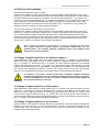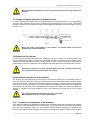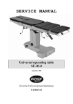
1
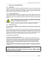
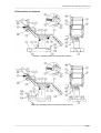
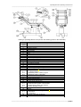
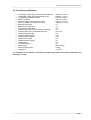
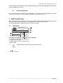
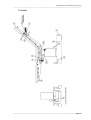
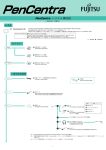
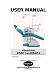
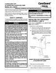
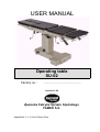
USER MANUAL
Operating table
SU-02
Factory no.:
.............................................
Version 12.00
Żywiecka Fabryka Sprzętu Szpitalnego
FAMED S.A.
Appendixes: 2, 3, A List of Spare Parts.
Operating Manual for Operating Table SU-02.0
_____________________________________________________________________________________________________
As provided in the Directive on Medical Equipment 93/42/EEC of 14 June 1993
this is first risk class product.
The producer declares that the product meets basic requirements of the
directive contained in Appendix 1.
The compliance procedure was carried out in accordance with appendix VII of
the directive.
Manufacturer:
Żywiec Hospital Equipment Company FAMED S.A.
Fabryczna 1
34-300 Żywiec
Phone numbers:
Infoline (+48 33) 866 63 75 (24-hours a day)
Head office (+48 33) 866 62 00
Marketing Department (+48 33) 866 63 00 ...02
Export Department (+48 33) 866 62 50 ... 52
Service (+48 33) 866 63 25
Fax (+48 33) 861 48 37
Medical device was registered at Registration Office of Healing Products, Medical Products
and Bio fight Products under no: PL/ DR 00 05 28
_________________________________________________________________________________
page 2
Operating Manual for Operating Table SU-02.0
_____________________________________________________________________________________________________
Dear Clients,
Congratulations on choosing the right product, we wish you would find a
lot of satisfaction while operating it.
Please read this manual very carefully as it includes all the vital
information and notes from the producer concerning proper installation
and maintenance of the product as well as its service.
Żywiecka Fabryka Sprzętu Szpitalnego
FAMED S.A.
General notes
•
•
•
The use, maintenance as well as servicing of this product performed in other
ways than those, which have been stated in this manual is forbidden and may
result in damages, which will encumber the user and which will not be a matter of
producer’s responsibility.
When the operation and parameters of the product do not match the description in
item ‘Operation’ in this manual, the use of the product is not allowed and any
defects have to be reported to the producer or the supplier.
Every repair of the product must be done by a factory or an authorized service
and recorded on the list of repairs, which is supplied with the guarantee certificate.
Disregarding this requirement will cause the guarantee for the product to be
invalid.
Notes concerned with safety
The sign shown below says: ‘Caution – pay special attention to the Operating Manual’.
A label showing this sign is placed on any parts or mechanisms, which may
prove to be harmful to the patient or the personnel if their operation does not
comply with the descriptions found in this Operating Manual.
•
Throughout surgical procedures table wheels should be blocked.
•
When using the table close to medical equipment working on high frequencies and
defibrillators one should closely follow operating instruction for that equipment.
Improper operation may become a source of dangerous accidents. There is a
danger of serious burning of the patient through the contact with metal parts of
the table or its equipment.
•
Throughout surgical procedures the table must be connected to the installation of
potential equalization in the operations room.
_________________________________________________________________________________
page 3
Operating Manual for Operating Table SU-02.0
_____________________________________________________________________________________________________
•
When performing longitudinal (Trendelenburg or reverse Trendelenburg) and
lateral tilting, patient should be secured against uncontrolled sliding down from
the operating table. Use shoulder supports, supporting rollers, side supports,
belts and grips as securing elements.
Notes concerning: start-up, operation and use
•
•
•
•
•
When anti-trendelenburg function is performed, footrests may collide with the
basis
The floor under the table should be free from any obstacles
When rolling the table avoid collisions
Do not roll the table over electric cables
If it is necessary to replace oil (dangerous waste), one should follow existing
environmental protection regulations
Notes concerning cleaning and disinfecting
•
•
•
•
The product must not be disinfected in disinfecting chambers!
No disinfecting agents containing alcohol are allowed for cleaning of polyurethane
elements (mattresses).
No bleaching agents (containing active chlorine or oxygen), caustic or corrosive
chemicals are allowed!
No agents destroying the structure of plastic (organic solvents) can be applied to
the plastic elements!
Disregarding the above requirements concerning cleaning and disinfecting shall
result in losing the guarantee for the product!
_________________________________________________________________________________
page 4
Operating Manual for Operating Table SU-02.0
_____________________________________________________________________________________________________
CONTENTS
1. PROPER USE AND APPLICATION ..............................................................................................................6
1.1. APPLICATION......................................................................................................................................................6
1.2. GENERAL REQUIREMENTS.....................................................................................................................................6
1.3. DUTIES OF THE USER ..........................................................................................................................................6
1.4 DESCRIPTION OF THE PRODUCT...............................................................................................................................6
1.5 DESCRIPTION OF ELEMENTS....................................................................................................................................7
1.6 TECHNICAL SPECIFICATIONS...................................................................................................................................9
1.7 USE PARAMETERS..............................................................................................................................................10
1.8 SAFETY............................................................................................................................................................11
1.9 CRITICAL PARAMETERS.......................................................................................................................................11
2 TRANSPORT AND FIRST USE......................................................................................................................12
2.1 TRANSPORT.......................................................................................................................................................12
2.2 UNPACKING AND FIRST USE..................................................................................................................................12
3 OPERATION AND USE...................................................................................................................................13
3.1 RAISING AND LEVELLING OF TABLE TOP.................................................................................................................13
3.2 LONGITUDINAL TILT OF THE TABLE-TOP.................................................................................................................13
3.3 TABLE TOP SIDE INCLINATION...............................................................................................................................14
3.4 CHANGE OF ANGULAR POSITION OF THE BACKREST SEGMENT.....................................................................................14
3.5 CHANGE OF ANGULAR POSITION OF KIDNEY BENCH .................................................................................................14
3.6 CHANGE OF ANGULAR POSITION OF THE FOOTRESTS.................................................................................................14
3.7 CHANGE OF ANGULAR POSITION OF DIVIDED FOOTRESTS ...........................................................................................15
3.8 ROTATION OF THE FOOTREST................................................................................................................................15
3.9 INSTALLATION AND REMOVAL OF THE FOOTREST......................................................................................................15
3.10 INSTALLATION AND OPERATION OF THE HEADREST.................................................................................................15
3.11 INSTALLATION AND DISMOUNTING OF MATTRESSES.................................................................................................16
3.12 TABLE MOBILITY..............................................................................................................................................16
3.13 ANTISTATIC PROPERTIES....................................................................................................................................16
3.14 POTENTIAL EQUALISING CLAMP ..........................................................................................................................16
3.15 COLLISIONS.....................................................................................................................................................17
4 INSTALLATION AND OPERATION OF ACCESSORIES.........................................................................18
5 CRITERIA ON WHOSE BASIS IT IS ASSESSED WHETHER PRODUCT OPERATION IS
CORRECT OR NOT............................................................................................................................................19
6 TABLE MAINTENANCE.................................................................................................................................19
6.1 STORAGE .........................................................................................................................................................19
6.2. CLEANING AND DISINFECTING ...........................................................................................................................20
6.3. DAMAGES AND DEFECTS.....................................................................................................................................20
6.4. REPAIRS AND INSPECTIONS..................................................................................................................................20
CONTROL OF TECHNICAL CONDITION...........................................................................................................................21
6.5. CONTROL OF TECHNICAL CONDITION.....................................................................................................................21
6.6. LOCATION OF DEFECTS AND THEIR REMOVAL.........................................................................................................21
6.7 PRODUCT LIQUIDATION.......................................................................................................................................22
7. TABLE IDENTIFICATION............................................................................................................................22
7.1. NAMEPLATE.....................................................................................................................................................22
7.2 LABELS...........................................................................................................................................................23
_________________________________________________________________________________
page 5
Operating Manual for Operating Table SU-02.0
_____________________________________________________________________________________________________
1.
Proper use and application
1.1.
Application
Operating table SU-02 is designed for supporting the patient during carrying out treatments and
operations. The table with proper accompanying equipment can be used for procedures of general
surgery, vascular surgery, cardiosurgery, neurosurgery, urology, gynecology, proctology, ENT,
endoscopy, laparoscopy, ophthalmology, trauma surgery, oncology surgery, dental surgery, plastic
surgery and others. Segments of the table-top are radiotransparent.
1.2.
General requirements
The product is intended to be used indoors. Required climatic conditions: temperature from +10 to
+40ºC, acceptable change of surrounding temperature during 8 hours should not exceed 20°C,
relative humidity of the air should range from 30 to 80%, atmospheric pressure from 700 to 1060 hPa.
The product should be used, maintained and serviced according to the instructions contained in this
manual.
Using, maintaining and servicing the product in other way than indicated in this
manual is not permitted and may lead to damages for which the user is to blame
and for which the producer is not responsible.
Caution! Installation of other accessories than those offered by the producer for the
product is allowed only on the basis of a written acceptance of the producer.
1.3.
Duties of the user
User: any individual or corporate body who uses the product as its owner, lessee, pledgee or who
has a different right to the product as well as an entity who uses the product on its own or on whose
behalf it is used.
The user must ensure that the product shall be used exclusively in conformity with its destination and
that it is used in appropriate conditions and in consistence with this manual. The user is also obliged to
take all necessary precautions in order to prevent all life and health hazards concerning the user,
patients and any third party. Only authorised persons who underwent special training and are
acquainted with this manual may operate the product. The user must also ensure that all persons who
operate the product have read, understood and apply instructions contained in this manual.
1.4 Description of the product
The table consist of table base and table top.
The table has a mobile base (standard or Supermobile – with large wheel), equipped with central
blockade, which is released with a foot lever. The top of the operation table is permanently attached to
the base. The table-top consists of segments, and their number and configuration is deliver according
to a customer order. The table top is X-ray permeable. The table top is provided with polyurethane
mattresses. On both sides of the table top there are side strips which allow to install accessories.
Adjustments of the position of individual segments, as well as column movements are performed by
mechanical systems.
Thanks to the wide range of offered accessories the table can be used for different types of operations
according to client wish. List of accessories can be found in Paragraph 4 - Installation and operation of
accessories.
The producer reserves the right to introduce in the product structural modifications resulting
from technical progress which are not covered in this user manual.
The producer reserve that all parameters and accessories can be modified or change
especially construction, technology and materials, not lowering accepted parameter
technically-user and safeties of products.
_________________________________________________________________________________
page 6
Operating Manual for Operating Table SU-02.0
_____________________________________________________________________________________________________
1.5 Description of elements
drawing 1 Operating table SU-02 (standard version)
drawing 2 Operating table SU-02 (Supermobile version)
_________________________________________________________________________________
page 7
Operating Manual for Operating Table SU-02.0
_____________________________________________________________________________________________________
drawing 2 Operating table SU-02 (version with steering panel on the head side)
item
on drawing
1-3
1
2
3
4
5
6
7
8
9
10
11
12
13
14
15
16
17
18
18.1
18.2
18.3
19
20
21
22
23
24
24.1
24.2
24.3
25
26
27
27.1
27.2
28
29
Description
Headrest
Backrest segment
Kidney bench
Seat segment
Footrest segment
Base
Column
Side strips
Potential equalising clamp
Hydraulic pump pedal (adjustment of table-top height)
Headrest angle change lever
Bolster blockade knob
Longitudinal tilt handle
Handle
Handle turn block
Backrest segment angle change lever
Blockade of lever of back support angle adjustment
Kidney bench crank
storage position
- adjustment position of kidney support
- adjustment position of lateral tilt
Crank sleeve of kidney support
Screw of kidney support mechanism
Footrest restoring knob
Footrest blockade lever
Footrest angle change lever
Pedal of central wheel blockade / feet ejection
- wheel unblocked position / feet elevated
- wheel blocked position / feet lowered
- direction blockade position
Feet
Wheels
Crank for side inclination angular change
– rest position
– work position
Blockade of lateral tilt angle knob
Shaft of lateral tilt device
_________________________________________________________________________________
page 8
Operating Manual for Operating Table SU-02.0
_____________________________________________________________________________________________________
1.6 Technical specifications
•
•
•
•
•
•
•
•
•
•
•
•
•
•
•
•
•
•
•
•
•
Total length of table top (4 and 5 sectional table top)
Total length of table top (6 sectional table top)
Total table-top width (with slats)
Width of mattress
Minimum height of the top from the floor
Maximum height of the top from the floor
Backrest raise angle
Backrest lowering angle
Kidney bench raise angle
Footrest raise angle (4 and 5 sectional table top)
Footrest raise angle ( 6 sectional table top)
Footrest lowering angle
Footrests widening angle
Angle of side inclination
Headrest raise angle
Headrest lowering angle
trendelenburg
anti-trendelenburg
Table weight
Nominal working load
Usage time
2025mm ± 15 mm
2160mm ± 15 mm
550 mm ± 5 mm
500 mm ± 5 mm
750 mm ± 15 mm
1000 mm ± 15 mm
70°
40°
110°
15°
45° (+45°)
90°
180°
± 25°
50°
20°
30°
25°
about 195 kg
150 kg
10 years
For the special client request it’s possibly to produce the product with change parameters, not
lowering it’s safety.
_________________________________________________________________________________
page 9
Operating Manual for Operating Table SU-02.0
_____________________________________________________________________________________________________
1.7 Use parameters
The figure below indicates the most important functional parameters of the table.
drawing 4
_________________________________________________________________________________
page 10
Operating Manual for Operating Table SU-02.0
_____________________________________________________________________________________________________
1.8 Safety
The structure of the table assures its safe operation and use if the rules provided in this manual are
followed.
Caution!
The sign shown below says: “Caution – pay special attention to the Operating Manual”.
A label showing this sign is placed on any parts or mechanisms, which may prove to be
harmful to the patient or the personnel if their operation does not comply with the descriptions
found in this Operating Manual.
When operating the table one should pay attention to elements and mechanisms with this
label.
•
Throughout surgical procedures table wheels should be blocked.
•
When using the table close to medical equipment working on high frequencies and
defibrillators one should closely follow operating instruction for that equipment. Improper
operation may become a source of dangerous accidents. There is a danger of serious
burning of the patient through the contact with metal parts of the table or its equipment.
•
Throughout surgical procedures the table must be connected to the installation of potential
equalization in the operations room.
•
When locking a set position of the footrest, pay attention that the toothed bars
correctly meshed.
•
When performing longitudinal (Trendelenburg or reverse Trendelenburg) and lateral tilting,
patient should be secured against uncontrolled sliding down from the operating table. Use
shoulder supports, supporting rollers, side supports, belts and grips as securing elements.
are
1.9 Critical parameters
Maximum work load
- 150 kg
Maximum authorized segment load
-head rest
-back rest segment
-seat segment
- foot rest (simple)
- foots rests (both load at the same time)
10 kg
55 kg
55 kg
15 kg
30 kg
fig.5
_________________________________________________________________________________
page 11
Operating Manual for Operating Table SU-02.0
_____________________________________________________________________________________________________
2 Transport and first use
2.1 Transport
There is a possibility to transport the product by any covered transport means. While transporting, it is
necessary to immobilize the truck and protect it against moisture. In case of lack of original packaging,
the product should be properly secured in order to prevent its damage, preferably by experienced
transport company.
The transport conditions are as follows:
-
temperature:
from –20OC to 60OC,
relative humidity: from 20% to 80%.
While product transporting, storage and unpacking, the temperature gradient should be less than 10 OC
per hour. It is strongly recommended to unpack the product after reaching room temperature.
Laminar storage is permissible in accordance with the packaging marking. In the absence of the
marking, storied storage is prohibited.
In case of the specific transport conditions (particularly: low temperature transport), it is necessary to
negotiate the way of transport and product packaging with the product manufacturer in order to ensure
safe transport.
2.2 Unpacking and first use
If the product is installed by an authorised service of FAMED S.A., the user is
released from the obligation to perform the activities described in this item.
Caution!
The table is shipped by the producer in an assembled form in a wooden, open-work chest or in a
cardboard box with the following dimensions L:1340 x W:700 x H:890 mm and weight 200 kg. To avoid
damaging of the product, it should be unpacked and installed in the building.
To prepare the table for operation after its transport or delivery one should:
- read carefully product operating manual
- take off the fastening tapes
- remove the package
- remove the materials protecting the table during its transportation.
Package may be marked with following signs:
- multiuse package
Caution!
- package for recycling
low-density polyethylene packaging
LDPE
Package waste is recyclable and should be segregated before removed to a
disposal site. Returnable packaging should be returned to the producer of the
medical product.
-
take out equipment
place the footrest horizontally (item 3.5 Change of angular position of the footrests)
remove blocking elements of the table,
_________________________________________________________________________________
page 12
Operating Manual for Operating Table SU-02.0
_____________________________________________________________________________________________________
-
release the central blockade of wheels (item 3.10 Table mobility)
with an assistance of a few people, carefully and slowly remove the table from the pallet, then
block the wheels
add the headrest (item 3.11 Installation and operation of the headrest)
place the product in its destination which meets the requirements described in this manual ( item
1.2 General requirements),
on the basis of information given in item 3 Operation check whether the table works as described
in item 5 Criteria on whose basis it is assessed whether product operation is correct or not.
-
Caution!
If the product is not fully functional, i.e. the output parameters differ from the
description contained in this manual, the bed must not be used. This situation
should be reported to the producer or supplier. The use of an improperly
functioning product may result in damages, which will encumber the user and
which will not be a matter of producer’s responsibility
3 Operation and use
3.1 Raising and levelling of table top
Height of table top is changed within the scope defined in technical data by pressing of the lever
(drawing 1-3, item 10) of the hydraulic pump. Table top is lowered when the lever is raised. The foot
pump installed in the table does not additional operation or maintenance.
3.2 Longitudinal tilt of the table-top
to adjust longitudinal tilt of the table-top (trendelenburg and anti-trendelenburg), you should stand
behind the backrest, put both hands on the handles (drawing 1-3 item 13 and 14), turn the right handle
clockwise till you feel resistance (which releases the blockade of gas springs) and place table top in
the required position (within the range of angles given in technical data). When you release the right
handle, the table will be locked in the position. Additionally after aggressive discharge of the right
handle an automatic return of its rotation blockade should follow. That is belonged to make sure for
this fact through another test of handle turning (to the right) without blockade releasing, rotation of the
handle should be impossible for execution.
Neurosurgical table top
Standard table top
Fig. 6
In neurosurgical table top the handle which is placed on the right side of the back rest segment should
be put forward and turn to the headrest side.
It belongs to dismiss the handle after receiving of demanded side.
Caution!
When performing longitudinal (Trendelenburg or reverse Trendelenburg) and lateral
tilting, patient should be secured against uncontrolled sliding down from the
operating table. Use shoulder supports, supporting rollers, side supports, belts
and grips as securing elements.
Make sure, that the rotation blockade of the right handle of longitudinal tilt
prevents its rotation!
_________________________________________________________________________________
page 13
Operating Manual for Operating Table SU-02.0
_____________________________________________________________________________________________________
3.3 Table top side inclination
Standard and Supermobile version of table
Lateral tilt of the table-top (within range specified in technical data) is performed with the use of the
crank (Fig. 1-2, position 27), located on the side of the table under the seat segment. In order to adjust
an angle of lateral tilt it is necessary to unfold the crank to the work position (Fig. 1-2, position 27.2)
and block it by pushing the blockade (Fig. 1-2, position 28) toward the column, and then by turning the
crank clockwise or counterclockwise adjust the angle of the table-top to the desired position. After
adjustment of the table-top put the crank in the rest position (Fig. 1-2, position 27.1) by pushing the
blockade toward the surgeon, and then folding it downward.
Version of the table with control panel on the head side
Lateral tilt of the table-top (within range specified in technical data) is performed with the use of the
crank (Fig. 3, position 18), placed in a sleeve (Fig. 3, position 19) located on the left side of the tabletop. In order to adjust the angle of lateral tilt place the crank on the shaft of lateral tilt device (Fig. 3,
position 29), which is located on the right side of back support. Then by turning the crank clockwise or
counterclockwise adjust the table-top to the desired position. Unused crank should be stored in the
sleeve (Fig. 3, position 19) located on the left side of the table-top
Caution!
When performing longitudinal (Trendelenburg or reverse Trendelenburg) and lateral
tilting, patient should be secured against uncontrolled sliding down from the
operating table. Use shoulder supports, supporting rollers, side supports, belts
and grips as securing elements.
3.4 Change of angular position of the backrest segment
Angle adjustment of the position of the back support segment (Fig. 1-3, position 2) is performed by
muscle force with a gas spring back-up. In order to adjust the segment position push the blockade
(Fig. 1-3, position 17), lift the lever (Fig. 1-3, position 16), then adjust the segment to the desired
position and release the lever (Fig. 1-3, position 16). Lever release blocks the mechanism of back
support segment and further move is impossible. It is important to remember to hold the segment with
both hands when adjusting the position. Thanks to the central position of the lever the backrest
segment can be operated from the right, from the left and from behind the backrest segment.
Caution!
If a patient is very heavy, over 90 kg, the angle of backrest segment should be
changed with particular care; one should be prepared that it would be necessary
to use considerable force to move it up and to cushion lowering at the moment of
lever release (drawing 1-3 item 16).
3.5 Change of angular position of kidney bench
Angle adjustment of the position of kidney support (Fig. 1-3, position 3) is performed with use of the
crank (Fig. 1-3, position 18), placed in the sleeve (Fig. 3, position 19) located on the left side of the
table-top. In order to adjust the position of the kidney support place the crank (Fig. 1-3, position 18.2)
on the screw of support mechanism (Fig. 1-3, position 20). Then by turning the crank clockwise or
counterclockwise adjust the support to the desired position. Unused crank should be kept in the sleeve
(Fig. 1-3, position 19) located on the left side of the table-top.
3.6 Change of angular position of the footrests
Angular position of the footrest is changed within the range defined in technical data by simultaneous
levering of the lever (drawing 1-3 item 23) and raising or lowering of the footrest segment to the
required level. When the pressure is removed from the lever, the mechanism is locked and the
position of the footrest determined.
_________________________________________________________________________________
page 14
Operating Manual for Operating Table SU-02.0
_____________________________________________________________________________________________________
When the anti-trendelenburg function is performed, the footrests may collide with
the base!
Caution!
3.7 Change of angular position of divided footrests
In order to change the angular position of divided footrest one should unscrew knob 1 or 2 (depending
on which of the footrest parts you want to adjust) till the toothed bars are out of mesh. The footrest
should be positioned in the required position and the adjusting toothed bar should be locked by turning
of knob 1 or 2.
Fig. 7
When one locks a set position of the footrest, one should make sure that the
toothed bar is correctly meshed.
Caution!
3.8 Rotation of the footrest
In order to put the footrests apart, the knob (drawing 1-3 item 21) shall be turned anticlockwise, that
causes toothed bar separation by a few mm and in that way the foot segment may be rotated around
vertical axis within the range provided in technical data. In order to lock the footrest the knob shall be
turned again but this time clockwise, then toothed bar will mesh and footrest movement will be locked.
Toothed bars must be correctly meshed! When the knob is being turned down,
one should check if the toothed bars are meshed.
Caution!
3.9 Installation and removal of the footrest
The footrest may be placed and removed from the seat segment thanks to the mechanism which is
moved by the lever (drawing 1-3 item 22). In order to remove the footrest segment one should hold the
segment by its bottom, pull the lever towards the segment (drawing 1-3 item 22) and take the segment
out of the hole in the seat segment. The footrest segment is installed by placement of the mandrel of
the segment in the opening in the seat segment and simultaneous pulling back of the lever. When the
segment is installed one should release the lever which thanks to a spring will get into its initial
position.
The segment should be held before the lever is released!
Make sure that the lever is in the right position!
Caution!
3.10
Installation and operation of the headrest
The headrest is fastened on installation wedges which are situated at the end of the backrest segment
using a knob. When the headrest is put on the stripe, one should determine its position by screwing
down the screw (drawing 1-3 item 12). The headrest is dismounted by unscrewing of the screw and
removal of the headrest from the stripe. The angle of the headrest is changed similarly to the backrest
_________________________________________________________________________________
page 15
Operating Manual for Operating Table SU-02.0
_____________________________________________________________________________________________________
segment, that is, by the handle which moves the mechanism of the gas spring. When the lever is
pressed, the required angle of the headrest may be chosen. Its release locks the headrest in the
chosen position.
Make sure that the headrest is locked!
Caution!
3.11
Installation and dismounting of mattresses
All mattresses can be removed without any tools. They are fixed on fixing pegs.
3.12
Table mobility
The table may move in all directions thanks to wheels fastened on its base. The table is provided with
movement blockade which is used during operations and procedures performed on the table.
Standard version and version with control panel on the head side
The table in this version is equipped with two feet, lowering of the feet cause the wheels to elevate and
loose contact with the floor, so that the table can not be rolled. Screwing or unscrewing of the feet
allows adjusting their projection. In order to lower the feet push the pedal toward the floor until you feel
resistance (Fig. 1,3, position 24.2). In order to elevate the feet lift the pedal to the upright position (Fig.
1,3, position 24.1).
Supermobile version of the table
The table in this version is equipped with central blockade of every wheel.
Pedal of central blockade has three positions:
-upper –direction blockade (Fig. 2, position 24.3),
- middle- all wheels unblocked (Fig. 2, position 24.1),
- lower – all wheels blocked (Fig. 2, position 24.2).
In “direction blockade” position one of the wheels is set for straight rolling. This position is used to roll
the table through long, straight distances, it facilitates turning the table. All-wheels blockade make the
table immobilized
Caution!
3.13
Throughout surgical procedures table wheels should be blocked.
The floor under the table must be free from any obstacles!
When rolling the table avoid collisions!
Do not roll the table over electric cables!
Antistatic properties
Table construction allows grounding of static charge through the following routes:
– By antistatic wheels to conducting floor,
– By potential equalisation clamp.
Operating table SU-02 should be used on antistatic floor. In case there is no such floor, a static charge
is grounded through the cord for potentials equalization. The potential equalising conductor is a
standard table accessory.
Antistatic properties of the table shall be maintained if mattresses produced by FAMED S.A. are used.
3.14
Potential equalising clamp
SU-02 operating table have inside system of potential equalization leading to the clamp (fig. 1-3, item
9) marked by symbol
.
_________________________________________________________________________________
page 16
Operating Manual for Operating Table SU-02.0
_____________________________________________________________________________________________________
Throughout surgical procedures the table must be connected to the installation of
potential equalization in the operations room.
Caution!
The cable is provided in standard table accessories.
3.15
Collisions
In some extreme positions of the table, in particular, when accessories installed on side stripes are
used, mechanical collisions may take place. Because of that, one should protect the table and
accessories from damages.
_________________________________________________________________________________
page 17
Operating Manual for Operating Table SU-02.0
_____________________________________________________________________________________________________
4 Installation and operation of accessories
The following extra accessories may be provided with the operating table SU-02:
accessory
Symbol
WS-01.5
1 Screen frame
2 Screen frame with width regulation
WS-01.6
3 Hand grip
WS-02.5
4 Thigh grip
WS-03.5
5 Shank grip
WS-04.5
6 Knee support
WS-05.5
7 Left and right arm support
WS-06.5
8 Hand angular support
WS-07.5
9 Big supporting bolster
WS-08.5
10 X-ray tray
WS-11.5
11 Trolley for accessories
WS-13.5
12 Grip for anaesthesiologic pipes
WS-14.5
13 Table for tools
WS-15.5
14 Single position stripe
WS-16.5
15 Multiposition clamp mechanism
WS-17.6
16 Multiposition clamp mechanism with shift
WS-17.7
blockade
17 Tray
for X-ray plate
WS-19.6
18 Specialist headrest
WS-21.5
19 Laryngology-ophthalmic headrest with track
WS-21.7
adjustment
20 Head rest for cervical kerb
WS-21.8
21 Hand support
WS-22.5
22 Body strap
WS-23.0
23 gynaecologic attachment
WS-28.5
24 urological attachment
WS-29.5
25 Proctologic attachment
WS-30.5
26 Complete handrails
WS-32.5
27 Side x-ray handle
WS-33.0
28 Wrist grip
WS-34.5
29 attachment do arthroscopy
WS-39.5
30 attachment for meniscus operation
WS-40.5
31 Belly belts
WS-41.0
32 Footrest belts
WS-42.0
33 Hand belt
WS-43.0
34 Thigh belt
WS-44.0
35 specialist head bolster - narrow
WS-45.5
36 specialist head bolster - wide
WS-46.5
37 attachment for hand surgery
WS-47.5
38 A support for hand surgery
WS-48.5
39 Womb support
WS-49.5
40 Side support
WS-50.5
41 Side rest with lever
WS-50.6
42 Chest support
WS-52.5
43 side stripe lengthening unit
WS-53.0
44 Shoulder side rest
WS-59.5
45 Lithotomic stirrups
WS-64.5
46 Mattress for backbone
WS-65.0
_________________________________________________________________________________
page 18
Operating Manual for Operating Table SU-02.0
_____________________________________________________________________________________________________
47
Semi-bolster
48
48
49
50
51
52
53
54
55
56
57
58
59
Bolster for neck
Bolster for neck
Head bolster
Upper arm operating support
Roller lift
Sieve for urological bowl
Not-divided leg-rest
Gynaecological-urological section
Drip hanger
Orthopaedic attachment
Orthopaedic attachment
Gynaecological attachment
Neurosurgery attachment
WS-66.0
WS-68.0
WS-68.0
WS-69.0
WS-87.5
WS-88.5
WS-89.5
SG-42.0
SG-44.0
WK-01.5
SO-09
SO-08.3
STIRRUPS
DORO
When ordering table accessories, please give table’s name and symbol.
The producer reserve the right to modyfy accesoriec according to clienr requirements and
produce new accesories complaing with norm of safety.
5 Criteria on whose basis it is assessed whether product operation
is correct or not
Caution!
Correctness of table operation shall be checked every day before the beginning of
its operation.
The method of checking whether operation of the table is correct:
1. Check stability of the table when its feet are down by trying to move the table manually: pushing of
the table in any direction should not cause tilting or moving.
2. Check mechanisms of adjustment of location of the segments controlled by gas springs by a
change of position and the lock (see item 3 Operation). The mechanism should work without
jamming, after locking the segment cannot change its position (check by manual pressing of the
segment).
3. Check if there are no mechanical plays by manually moving the top of the table.
4. Check the work of the hydraulic system by raising of table column using the foot pump.
If the table underwent the above described tests with positive results and there were no disturbing
sounds (squeaks and grinds), the table can be used safely.
Otherwise see item 6.6 ‘Location of defects and their removal’.
Caution!
If the product is not fully functional, i.e. the output parameters differ from the
description contained in this manual, the bed must not be used. This situation
should be reported to the producer or supplier (dealer). The use of an improperly
functioning product may result in damages, which will encumber the user and
which will not be a matter of producer’s responsibility.
6 Table maintenance
6.1 Storage
If the product is not to be used for a longer period of time, it should be stored in the below mentioned
climatic conditions:
• temperature: 25º ±10ºC,
_________________________________________________________________________________
page 19
Operating Manual for Operating Table SU-02.0
_____________________________________________________________________________________________________
•
relative humidity: 50% ± 25%.
6.2. Cleaning and disinfecting
For cleaning and disinfecting use cleaning solutions free from bleaching agents (active oxygen or
chlorine), recommended by Famed S.A. in Annex 2 to this manual (allowed to turnover and use on the
territory of the country, where they are used)
After disinfecting wash the product with distilled water to remove stains.
After disinfecting dry thoroughly.
Dry with hot air (max. temp. 60°C) or by wiping with a soft sterile cloth.
Cleaning and disinfecting should be carried out in accordance with Appendix 4.
The product must not be disinfected in disinfecting chambers.
Bleaching (containing active chlorine or oxygen), caustic and corrosive agents
must not be used.
Caution! No agents destroying the structure of plastic (organic solvents) may be applied to
the plastic elements.
Before cleaning or disinfecting disconnect from mains!
During cleaning and disinfecting of the control be particularly careful. If the
control gets drenched, dry it as soon as possible and dry its edges with a cloth!
Disregarding the above requirements concerning cleaning and disinfecting shall result in
losing the guarantee for the product.
6.3.
Damages and defects
Damages and defects found in the product or product accessories should be reported immediately to a
person in charge of such issues. The bed which can not be safely operated (e.g. damaged electric or
mechanical elements ) must not be used till it is repaired.
6.4.
Repairs and inspections
Repairs are done by the producer or an authorised service. The user can not carry out any repairs on
his own unless he has undergone special training or has been authorised to do that. When the
producer has given his written permission for repair of the product by client’s technical staff, the
producer shall provide the client with necessary charts, lists of spare parts, descriptions and
information on repairs.
The producer allows only to use original spare parts. In order to provide safe and reliable operation of
the product one should use only spare parts provided by the producer. Worn out parts shall be
removed as provided in environmental protection regulations.
The product contains products which may be dangerous to the environment:
Caution!
- oil (pneumatic spring),
The rules of proceeding with used products which may be dangerous to the
environment are defined in regulations related to proceeding with waste.
Repairs and maintenance must be performed only by qualified personnel. If a product is operated
outside Poland, one should inform about a necessity of a repair a producer or the dealer from whom
the product was purchased.
Every repair of the product must be recorded on the list of repairs enclosed with the guarantee
certificate.
_________________________________________________________________________________
page 20
Operating Manual for Operating Table SU-02.0
_____________________________________________________________________________________________________
.
6.5 Control of technical condition
In order to ensure safe and proper technical condition of the product during the whole life of
the product, the product should undergo periodical technical inspections to be carried out by
the producer, an authorised service or authorised and trained technical staff of the customer
(at the expense of the user).
Only a positive result of product inspection can be the basis for its further operation.
The required service and its frequency are shown in the table below.
-
Subject of inspection
Checking functionality and general technical condition
(according to service instructions)
frequency
Every 12 months
Every repair of the product should be recorded on the list of repairs enclosed to
the guarantee card on pain of guarantee loss!
Caution!
6.5.
Control of technical condition
In order to provide safe and correct operation during product life, the user should perform the
following activities every six months:
Table basis
− Check screw joints and protections on pivot bolts
− Check whether the lock and table moving system work
− Check the hydraulic pump
− Check whether gas springs work correctly
Table top
− check whether the trendelenburg mechanism works correctly
− check whether the blockade of footrest fixing clamp works properly
− check whether gas springs work correctly
Accessories
− check functionality
− check whether blockades work correctly
Potential equalising
− check the condition of insulation (cracks)
cable
− check how good the connection is
A checkout should involve a visual inspection and the noticed malfunctions should be handled as
provided in item 6.6 Location of defects and their removal.
6.6.
Location of defects and their removal
A list of repairs which may be carried out by the client on his own.
damage
The table
cannot be
moved
The
trendelenburg
mechanism
does not work
The table is not
stable
Plays in screw
joints
Possible cause
removal
locked wheels
Unlock blockade pedal
The mechanism of
trendelenburg wire
wrongly adjusted
Regulate wire mechanism in accordance with the
item: Table repairs and adjustment
Wrong adjustment
of table feet
Plays appeared
during product
operation
Unscrew or screw down feet with a wrench
Screw down with generally available wrenches
_________________________________________________________________________________
page 21
Operating Manual for Operating Table SU-02.0
_____________________________________________________________________________________________________
If the fault cannot be eliminated, put the product aside and call the repair department, local service
center or FAMED S.A’s service.
6.7
Product liquidation
If the customer resign from further product exploitation, he is obliged to product liquidation according
to rules of environment protection, detailed information is situated in annex no. 3.
7. Table identification
When sending/ asking any questions concerning the table and when ordering spare parts, please give
the serial number of the table placed on the nameplate and the guarantee certificate.
The second nameplate is located under column casing (covered).
7.1.
Nameplate
FAMED ŻYWIEC S.A.
34-300 Żywiec, ul. Fabryczna 1
POLAND
Symbol:
3
4
SU-02
1
2
5
SN 0103/00008
TBL-050007XXXXXXX
6
Description of individual components of the nameplate
1 – Producer’s name, trademark (address),
2 – Symbol of the product,
3 – Serial Number (country of manufacture),
4 Product Index
5 -
6–
Attention!! Before the first use read operating manual,
CE Sign,
_________________________________________________________________________________
page 22
Operating Manual for Operating Table SU-02.0
_____________________________________________________________________________________________________
7.2 Labels
_________________________________________________________________________________
page 23
Operating Manual for Operating Table SU-02.0
_____________________________________________________________________________________________________
1
2
1. Potential equalising clamp.
See point 7.1
Nameplate
3
Transport position of the table
4
For cleaning and disinfection you should not use agents containing
active oxygen and chlorine
5
Maximum authorized workload 150 kg
6
Attention – read user manual
Longitudinal tilt (Trendelenburg, anti-Trendelenburg)
7
8
Kidney elevator adjustment (only in table-top with kidney support)
9
Head rest adjustment
10
Back rest adjustment
Transverse tilt
11
12
Leg rest adjustment
_________________________________________________________________________________
page 24
Operating Manual for Operating Table SU-02.0
_____________________________________________________________________________________________________
13
Table top height adjustment
14
Table’s brake
15
Central wheel lock
Notice!
The producer reserves the right to introduce in the product
modifications resulting from technical progress which are not covered in
this operating manual.
_________________________________________________________________________________
page 25
Operating Manual for Operating Table SU-02.0
_____________________________________________________________________________________________________
Item:
Edition:
SU-02
August 2007
Spare Parts List
SJW-4-01-02
Basic spare parts
No Name
1
2
3
4
5
6
7
8
9
10
11
12
13
14
15
16
17
18
19
20
21
22
23
24
25
26
27
28
29
30
31
32
33
34
35
37
pcs/set
4
Wheel
1
Wheel
1
Trendelenburg mechanism
2
Small foot set
1
Driving unit - set
8
Roller
Ball bearing - standard ( for a roller) 16
4
Bearing
1
Protection set
1
Interlocking toe
1
Stable protection set
1
Movable protection set
1
Top protection shield set
1
Potential balance cable
1
Pin of potential balance
4
Sliding sleeve
4
Guiding sleeve
1
Trendelenburg pin
3
Grounding cable
2
Spring
2
Spring
2
Footstool grip
1
Worm set
1
Driver
2
Driving unit of head rest
2
Driving unit of back rest
2
Driving unit of footstool
1
Bearing
1
Bearing
2
Starlock
1
Screw
1
set
Wheels
2
Break pin
2
Break lever
2
Shaft
1
Slider set
Code number
R60013-100-02000
R60013-125-02000
C047307000000000
C047301060000000
C047302000000000
C047305000007000
S06310000060010
S06310001100001
C047301010000000
C047301030000000
C047308000000000
C047309000000000
C047310000000000
S1115000004258
S11155000004256
S30250100000200
C073600000014000
C047300000003000
C047300001100000
C047301000008000
C047311000012000
C047311030000000
C047317000002000
C047300000013000
C047314070000000
C047311040000000
C047312030000000
S06310001110000
S06310000700000
R50010-08-02-000
C080300001100000
R60012-125-10000
C043306000400000
C043306000500000
C106601000007000
C106601050000000
CategoryRemarks
1
1
1
2
1
1
2
2
3
2
3
3
3
2
2
2
2
2
2
1
1
2
2
2
1
1
1
2
2
1
2
1
3
2
2
3
SU-02.0
SU-02.0
SU-02.0
SU-02.0
SU-02.0
SU-02.5
SU-02.5
SU-02.5
SU-02.5
SU-02.5
_________________________________________________________________________________
page 26
Operating Manual for Operating Table SU-02.0
_____________________________________________________________________________________________________
35
36
37
38
39
40
41
42
43
44
45
46
47
48
49
50
51
52
53
54
55
56
57
58
Base protection
Foot lever of interlocking
Back rest matress
Matress set I
Matress set II
Seat matress
Footstool matress
Head rest matress
Head rest rail
Handwheel
Side rail
Back rest rail I
Crank set
Protection
Arm
Screw
Hand II
Protection set
Shaft set.
Bering 3202
Flexible cllutch
Worm
Cardan joint
Gear
1
1
1
1
1
1
1
1
2
2
2
2
1
1
1
1
1
1
1
1
1
1
1
1
C106601030000000
C106601020000000
C080203000000000
C080300000042000
C080300000043000
C090103000000000
C080805000000000
C080105000000000
C047314000008000
R30057-100500251
C047311000019000
C047311000020000
C067204000000000
C067200000005000
C080300000700000
C080300000011000
C047311000011000
C081301020000000
C134207000000000
S063100003010000
S06340000001000
C080628000002000
S092000000101200
S063450000020000
3
2
3
3
3
3
3
3
2
2
2
2
2
3
2
2
2
3
3
2
2
2
2
2
Qt.
Code number
Remarks
SU-02.5
SU-02.5
SU-02.1
SU-02.1
SU-02.1
SU-02.1
SU-02.1
SU-02.1
SU-02.1
Repair kit
No Name
1
2
Legend
Markers in column „Kategory”
1 - The elements endanger fast wear out
2 - The elements not endanger fast wear out
3 - The elements wear out depended of condition of ekxploitation
_________________________________________________________________________________
page 27
Operating Manual for Operating Table SU-02.0
_____________________________________________________________________________________________________
Part completeness list
Symbol: SU-02
Edition: 06.04.2007
Package should contain:
Operating table SU-02 set (without
headrest)
1 pce
and:
Headrest
1 pce
Potential equalization cord
1 pce index:
Additional equipment
SG-10.0
S11155000015625
According to order
Without the figure
Date and packer’s seal
_________________________________________________________________________________
page 28