1
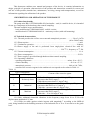
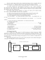
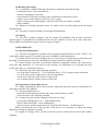
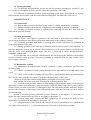
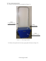
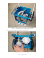
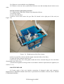
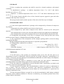
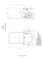
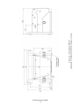
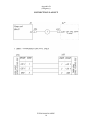
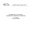
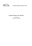
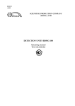
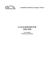
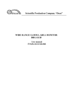
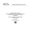
Scientific Production Company “Doza” PUMP UNIT BN-01 User Manual FVKM.064424.RE Cont ent 1 Description and operation of the product ……………………….. 1.1 Product functionality ……………………………………….. 1.2 Technical characteristics …………………………………… 1.3 Design and operation …………....………………………..… 1.4 Marking and sealing …………………...………………...…. 1.5 Packing ………………………………………….….…….… 2 Intended use ………………………………………….……….… 2.1 Operational limitations ………………………………...…… 2.2 Preparation of the product for use ..………………………… 2.3 Testing operability …….….….………………………..….… 3 Maintenance …………………………………………………..… 3.1 General notes ……………………………………………..… 3.2 Safety precautions ………………………………………..… 3.3 Maintenance routine ……………………………………...… 3.4 Vane replacement procedure ……………..........................… 3.5 Filter element replacement procedure .…………………...… 4 Routine repairs ……………………………………………..…… 5 Storage …………………………………………………………... 6 Transportation ……………………………………………...…… 7 Disposal ………………………………………………………..... Appendix A Outline drawing ……………………………………... Appendix B Connection layout …………………………………… FVKM.064424.002RE 2 3 3 3 4 5 5 5 5 5 5 6 6 6 6 6 9 9 10 10 10 11 13 This document combines user manual and passport of the device; it contains information on design, principle of operation, characteristics of the product and instructions essential for correct and safe use of this product (intended use, maintenance, servicing, storage and transportation), as well as information regarding the utilization of the product. 1 DESCRIPTION AND OPERATION OF THE PRODUCT 1.1 Product functionality The pump units BN-01 FVKM.064424.002 (hereinafter – unit) is a mobile device; it is intended for use as a component of the hardware that controls sampling. The unit available in two modifications: - basic modification FVKM.064424.002 - mobile version; - modification 01 FVKM.064424.002-01 - stationary version (with wall mounting). 1.2 Technical characteristics 1.2.1 The unit provides the air flow rate at normal atmospheric pressure ..……... 2.4 to 3.0 m3/h (40 to 50 dm3/min). 1.2.2 Warm-up time ….………………………...….……………………….…………….. 1 min. 1.2.3 Continuous operation ….………………………...…..…………………………... 24 hours. 1.2.4 Power supply of the unit is performed from single-phase electrical line with AC 2.5 voltage ………………………………………………………………….. 220 22 33 V, frequency 50 2.5 Hz. 1.2.5 Current consumption ……………………….…..…………..….…………..….……. 1.1 A. 1.2.6 Power consumption ………………..………..…………………………………….. 50 VA. 1.2.7 Power supply is provided through hardware that controls sampling. 1.2.8 Operating conditions: - operating temperature …………………………….…………….……… minus 10 to +50 °C; - relative humidity …………..………………..…………..……………..…… 98 % at +35 C; - atmospheric pressure …………………………………….…………….… 84.0 to 106.7 kPa; - content of the corrosive agents in the ambient air corresponds to the values in Table 1.1. Table 1.1 Type of atmosphere Designation Description I Relatively clean II Industrial III Maritime Content of the corrosive agents Sulfur dioxide gas no more than 20 mg/(m2·day) (not more than 0.025 mg/m3); Chlorides not more than 0.3 mg/(m2·day) Sulfur dioxide gas no more than 20 to 250 mg/(m2·day) (not more than 0.025 to 0.31 mg/m3); Chlorides - not more than 0.3 mg/(m2·day) Sulfur dioxide gas not more than 20 mg/(m2·day) (not more than 0.025 mg/m3); Chlorides – 30 to 300 mg/(m2·day) 1.2.9 Units withstand sinusoidal vibrations in the frequency range from 10 to 55 Hz with displacement amplitude 0.35 mm. 1.2.10 Units are stable against seismic impacts with magnitude 7 according to the MSK-64 scale, being installed on the building structures of the industrial site at 70 to 30 m relative to the grade level. FVKM.064424.002RE 3 After the seismic impact with the above mentioned parameters units are operable within the limits stated in sections 1.2.1 during the whole life cycle under specified operation conditions. 1.2.11 Degree of protection provided by casings against ingress of solid items and water - IP23. 1.2.12 Units withstand the electromagnetic interference of the 3 grade according to IEC 1000-4-8-93, IEC 1000-4-9-93, IEC 61000-4-2-95, IEC 61000-4-3:2006, IEC 61000-4-4:2004, IEC 61000-4-5-95, IEC 61000-4-6-96, IEC 61000-4-11:2004, IEC 61000-4-12-95, IEC 61000-4-13:2002, IEC 61000-4-14-99, IEC 61000-4-28-99. 1.2.13 Units comply with the standards for emission set forth by IEC 61000-3-2:2005, IEC 61000-3-3:2008 and CISPR 22:2006 for class A equipment. 1.2.14 By its protection against electric shock units comply with the IEC 61010-1:2001. 1.2.15 Units are fire-safe products with fire probability of no more than 10-6 year-1. 1.2.16 Units withstand the exposure to decontaminating solutions: - boric acid (H3BO3) – 16 g, sodium thiosulfate (Na2S2O3·5H2O) – 10 g, distilled water – up to 1 liter; - trisodium phosphate or sodium hexametaphosphate (any detergent) – 10 - 20 g/l water solution; - 5 % citric acid solution in rectified alcohol – for connectors and contacts. 1.2.17 Weight, not more than: - basic modification ..………......…..…………………...…….…..…………..……..… 22.1 kg; - modification 01 ………………......……...…..….………………….…...……..……..… 24 kg. 1.2.18 Overall dimensions - basic modification .…...……………..…...….…..…...………....…..…..… 472×343×975 mm; - modification 01 ...………………......……...….…..…..………...……..…. 532×400×354 mm. 1.2.19 Mean time before failure …………………….………………. not less than 20000 hours. 1.2.20 Mean life time ………………………………….….…………..…. not less than 10 years. 1.3 Design and operation 1.3.1 A sliding vane rotary pump SV 1003D developed by Busch Productions GMBH manufacture is used in the unit. The pump unit pumps air through the measuring instrument. A gas filter is provided before the pump; it serves as a receiver smoothing pressure pulsations in the sampling tube and performs accident-related cleaning of the pumped air in case of failure of standard filters of measuring devices. After passing through the filter the air enters into the pump and is then exhausted through the outlet pipe to the atmosphere or to the ventilation system. Air back to ventilation system Measuring device Filter Ventilation FVKM.064424.002RE 4 Pump 1.4 Marking and sealing 1.4.1 A nameplate with the following information is attached to the unit housing: - trademark or name of the manufacturer; - reference designation of the unit; - works number of the unit according to the manufacturer numeration system; - voltage, current and frequency of the AC power supply; - degree of ingress protection against solid items and water provided by casings$ - made in Russia. 1.4.2 Method of marking and place where it is made on the unit shall comply with the design documentation. 1.4.3 The unit is sealed according to the design documentation. 1.5 Packing 1.5.1 The unit’s package complies with the design documentation and provides protection against ingress of atmospheric precipitations and aerosols, splashes of water, dust, sand, solar ultraviolet radiation and limits the ingress of water vapour and gases. 2 INTENDED USE 2.1 Operational limitations 2.1.1 The unit is designed for operation with equipment manufactured by the SPC “Doza”. Use of the unit for other purposes is possible only after consultation with manufacturer. 2.1.2 When the unit is used in sampling lines, it is necessary to exclude ingress of moisture into the pump. For this purpose in the line entrainment separators and driers shall be provided. 2.1.3 Power supply to the unit is provided by hardware compatible with the unit. If the unit is used with other hardware, it is necessary to take measures for installation of an external electrical switch and a fuse or a switching-off device. 2.1.4 The following is not allowed during operation: - use of the unit at medium (6 – 35 kV) and high (above 35 kV) voltage electric substation; - use of the unit as parts of high power electric installations; - connection of the unit to the circuit of signal earth; - use of mobile phones within 10 meters of the unit. 2.2 Preparation of the product for use 2.2.1 When switching the unit for the first time, unpack the unit and check its completeness in accordance with this User Manual. 2.2.2 For unit modification 01: - mount the wall mounting assembly that comes with the unit on a wall; - secure the unit to the mounting assembly. 2.2.3 Connect the unit with the sampling control device using: - power cable FVKM.685631.211 – both modifications: - hose FVKM.302645.006 – basic modification; - silicone tube for medical applications TU 9436 04-18037666-94 – modification 01. When connecting the unit to the gas line of the device, it is necessary to follow the wiring diagram according to Appendix A and B. 2.2.4 Apply AC voltage 220 V (50 Hz) to the unit’s power socket from the device that controls sampling. FVKM.064424.002RE 5 2.3 Testing operability 2.3.1 To check the unit operability, prepare the unit for operation according to sections 2.1 and 2.2. Use devices compatible with the unit for testing the operability of the unit. 2.3.2 The unit is considered operable if after switching on the motor starts and the air is being sucked into the air inlet tube «AIR IN» and exhausted through the air outlet tube «AIR OUT». 3 MAINTENANCE 3.1 General notes 3.1.1 Follow safety measures described in the section 3.2 during maintenance operations. 3.1.2 During external examination the completeness and marking of the unit are checked. 3.1.3 Cleaning of external surfaces is performed for removing dirt and dust. Soft cloth and brush can be used for cleaning. 3.2 Safety precautions 3.2.1 All works, with regard to operation of the unit shall be performed in accordance with current safety instructions and radiation protection instructions of the company (facility). 3.2.2 Technical personnel with skills of working with electric equipment are permitted to perform maintenance of the unit. 3.2.3 During operation of the unit special attention shall be paid to power cord condition – in this place dangerous voltage can be present. All disconnections of the cables shall be carried out only with the power cord unplugged from mains. The unit is connected to mains through hardware, compatible with the unit. In case when the unit is used with other hardware, it is necessary to take measures on providing external electrical switch and fuse. Protective grounding is connected with the third contact of the power supply connector. 3.3 Maintenance routine 3.3.1 Maintenance includes periodic check of conditions of cables, connections, gas filters and the unit’s pump. 3.3.2 Checks of condition of cables and connections of the unit shall be performed at least once a year. 3.3.3 Check of the condition of pump and a gas filter is performed by means of monitoring the unit’s air flow rate using the flow meter. The airflow shall be at least 40 dm3/min. Checks of the gas filter and the pump shall be performed at least every month. If the airflow rate of the pump unit decreases, the following shall be done: 3.3.3.1 Check of the gas filter without its dismantling is performed by means of checking the inlet/outlet pressure drop (difference) at the test nipples, while the outlet of the filter is closed and the pressure in the gas main of the filter is 1 atmosphere (bar). The inlet/outlet pressure difference shall be not more than 10 mbar, or increasing of the inlet/outlet pressure difference since the last check shall be less than twofold. In case of increasing of the inlet/outlet pressure difference at test nipples, it is necessary to replace the filter element on the gas filter in accordance with section 3.5. 3.3.3.2 Check pump vanes wearing and their replacement (if necessary) for units of basic modification is performed in accordance with section 3.4. 3.3.3.3 Replacement of filter element and vanes of the units of modification 01 is performed in accordance with sections 3.4 – 3.5, after disconnection of the unit from mounting assembly. FVKM.064424.002RE 6 3.4 Vane replacement procedure 3.4.1 Unscrew four bolts and remove the handle (see Figure 3.1). Handle FVKM.303658.004 Panel FVKM.745222.009 Panel FVKM.735332.002 Figur e 3.1 – Removing the handle 3.4.2 Remove front panel and, if necessary, upper panel of the unit (see Figure 3.2). FVKM.064424.002RE 7 Figur e 3.2 – Removing the front and upper panel of the unit 3.4.3 Unscrew screws and remove the pump lid (see Figure 3.3). Figur e 3.3 – Removing the pump lid FVKM.064424.002RE 8 3.4.4 Unscrew screws and take away diaphragm. 3.4.5 Remove worn-out vanes; replace them with new ones and assembly the unit in the reverse order. 3.5 Filter element replacement procedure 3.5.1 Replacement of the filter element is performed as follows: 1) cut the gas supply; 2) remove the unit panel; 3) unscrew screws and remove the gas filter lid located in the right part of the unit (see Figure 3.4); Filter Figur e 3.4 – Replacement of the filter element 4) take away the filter element and thoroughly clean the hollow of the filter; 5) replace the filter element with new one; 6) insert the gas filter lid so that guides inside the lid are oriented along one line with filter element then screw the screws; 7) check the air tightness of the gas filter in accordance with the requirements air tightness (see section 3.3.3.1). 4 ROUTINE REPAIR 4.1 Current repair of the unit includes restoration of damaged cables and connectors. Replacement of individual modules and blocks is performed in accordance with the Service Manual FVKM.064424.002RO. FVKM.064424.002RE 9 5 STORAGE 5.1 Prior to putting into operation unit shall be stored in a heated warehouse with natural ventilation: - in manufacturer’s package – at ambient temperatures from +5 to +40 C and relative humidity up to 80 % at +25C; - unpacked – at ambient temperatures from +10 to +35 C and relative humidity up to 80 % at +25 C. 5.2 The storage location should be free of dust, chemical vapours, aggressive gases and other substances that may cause corrosion. The storage location shall exclude exposure of the unit to the direct rays of sunlight. 6 TRANSPORTATION 6.1 Units in the original manufacturer’s package can be transported by all means of transport at any distance: - transportation by railway shall be carried out in clean boxcars; - when transported by open motor transport boxes shall be covered by the water-proof material; - when transported by air the boxes with units shall be placed in air-tight heated compartment; - when transported by water and sea transport the boxes with units shall be placed in the hold. 6.2 Arrangement and fastening of the boxes on transport means shall provide their steady position en route, absence of displacement and striking each other. 6.3 The requirements of the inscriptions on the transport packing shall be observed during loading and unloading. During loading and unloading units shall not be exposed to precipitations. 6.4 Transportation conditions are as follows: - temperature ………………………………………….………..….. from minus 25 to +50 °C; - humidity …………………………………….…….…………....…..… up to 98 % at +35 °C; - sinusoidal vibrations ………..………………….. within frequency range from 10 to 55 Hz with displacement amplitude 0.35 mm. 7 DISPOSAL 7.1 On full expiry of the product (its component parts) service life and also prior to its dispatching for repair or calibration it shall be inspected for possible radioactive contamination of its surfaces. Criteria for decision making on decontamination and further use shall comply with obligatory requirements of national standards. 7.2 Decontamination shall be attempted in cases when the unit surfaces contamination (including surfaces accessible during repair) can be reduced below allowable limits. In case the radioactive contamination exceeds allowable limits, requirements set forth for the radioactive wastes become applicable to the unit. 7.3 Unit accepted for operation after decontamination is subject for repair or replacement in case of failure. Unit not suitable for operation, with radioactive contamination levels below permissible limits, should be dismantled to prevent further use and transferred to a special site for disposal of industrial wastes. 7.4 Unit with expired lifetime, accepted for use after decontamination, shall undergo technical inspection. If the technical condition of a detector is satisfactory, an extended operation term of the product shall be determined. FVKM.064424.002RE 10 FVKM.064424.002RE 11 OUTLINE DRAWING Appendix A (Obligatory) FVKM.064424.002RE 12 Figure А.1 – The pump units BN-01 basic modification FVKM.064424.002 (mobile version) FVKM.064424.002RE 13 Figure А.2 – The pump units BN-01 modification 01 FVKM.064424.002-01 (stationary version) Appendix B (obligatory) CONNECTION LAYOUT FVKM.064424.002RE 14 FVKM.064424.002RE 15