1
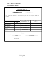
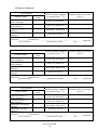
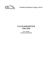
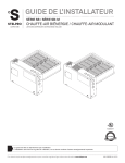
436150 ОКП SCIENTIFIC PRODUCTION COMPANY «DOZA», LTD DETECTION UNITS BDMG-100 Operating manual ТЕ2.328.022OM Cont ent 1 Description and operation of the product ………………………………......... 1.1 Unit designation ………………………………………….……..…… 1.2 Technical characteristics …………………………………………..… 1.3 Configuration of a product …………………………………..………. 1.4 Design and operation …………....………………………...………… 1.5 Marking and sealing …………………...………...………………..… 1.6 Packaging ……………………………………………………..……... 2 Use to Destination …………………………………..………………….……. 2.1 Operation limitations ……………………..……….………………… 2.2 Preparation of a product for use ..…………………………..…...…… 2.3 Use of a product …….…………………………..……………...……. 3 Technical Maintenance ………………………………...………………...….. 3.1 General instructions………………………………..…………...……. 3.2 Safety Requirements …………………………………………...….… 3.3 Maintenance routine…………………..……………………….…..… 4 Calibration method …………………….………………………..…………... 4.1 General requirements …………………………………..……..…….. 4.2 Operations and means of calibration ……………………...…….…... 4.3 Safety requirements ……………………………………..…………... 4.4 Calibration conditions and preparation ………….……………..….… 4.5 Carrying out of calibration ……………………………………..…… 4.6 Results presentation of the calibration …………………..………….. 5 Data about calibration ……………………………………….…………...….. 6 Current repair …………………………………..………………….……….... 7 Storage ………………………………………………………..……………... 8 Transportation ……………………………………………..………………… 9 Recycling…………………………………………………..……………..…... 10 Composition of the set …………………………………………………….... 11 Warranty ……………………………...…………………………….………. 12 Acceptance certificate …………………………………..………………….. 3 3 3 4 4 5 5 5 5 5 5 6 6 6 6 6 6 7 7 7 7 8 9 14 14 14 14 15 16 17 Appendix А Designation of contacts of sockets ………………………………. Appendix B Overall and mounting dimensions ………………..……………… 18 20 ТЕ2.328.022ОМ 2 This operating manual contains information on the construction, operation, product specifications and instructions necessary for proper and safe use (intended use, maintenance, current repair, storage and transportation), as well as information on the disposal of the product. 1 Description and operation of the product 1.1 Unit designation Detection units BDMG-100 ТЕ2.328.022 (hereinafter referred to as unit) are manufactured in compliance with the requirements TU 4361-066-31867313-2006 and are designed for continuous * 10 hereinafter referred to as power conversion of gamma-radiation ambient dose equivalent PADE) into electric pulse frequency. The unit is intended to control radiation environment at industrial facilities: nuclear power plants, radwaste processing and utilizing plants, adjacent areas, being part of systems, complexes and systems of radiation control. The unit is available in configurations that differ only in the type of connector and the parameters of output signal: BDMG-100, BDMG-100-01 BDMG-100-02, BDMG-100-03, BDMG-100-07. The unit can work together with the counting-rate meter dual-channel UIM2-2D, data processing and transmission units BOP-1, BOP-1m and interface unit BS-11. 1.2 Technical characteristics 1.2.1 Gamma-radiation energy range ...….……………....……………… from 0,05 to 3,0 MeV. 1.2.2 Range of PADE conversion: - sensitive subrange ……….…..………...…………….…...….. from 0,1 µSv·h-1 to 2 mSv·h-1. - crude subrange ..………........……………………….…..….... from 0,5 mSv·h-1 to 10 Sv·h-1. 1.2.3 Conversion function takes the form * 10 K N , (1.1) 1 MN * 10 - PADE of gamma-radiation; where 1 K - conversion factor, response reciprocal value η; N - pulse count rate, count·s-1 ; М - «dead time», s. * 10 and К: [µSv·h-1] и [µSv·h-1/count·s-1] – for sensitive subrange, Quantity dimension [mSv·h-1] and [mSv·h-1/count·s-1] - for crude subrange. 1.2.4 Limits of admissible essential relative accuracy of gamma-radiation PADE conversion ……………………………………..…………… ±(15 +3/Н) %, where Н – a dimensionless quantity equal to the measured value of PADE in µSv·h-1. 1.2.5 Gamma-radiation sensitivity: - sensitive subrange ……..……….….………….………....… (4,4 ±0,8) count/s for 1 µSv·h-1; - crude subrange .…...………….…………..……………….. (5,0 ±3,0) count/s for 1 mSv·h-1. 1.2.6 Response dependence from radiation energy relative to active energy 0,661 MeV .....……………………………………..….........................…... not to exceed ±30 %. 1.2.7 Unit operation mode setup time .......….................….……………. does not exceed 1 min. 1.2.8 Run time without limitation of on/off ……………….……………..................... unlimited. 1.2.9 Indication instability for over 24 hours of continuous work relating to mean value of indication for that period doesn't exceed .............................................……...…...……………… ±10 %. ТЕ2.328.022ОМ 3 1.2.10 DC supply voltage ………….……………..…...….....................................…..…. +12 V. 1.2.11 The unit is resistant to change in the voltage supply in the range ………………………………………….......……………………………… from +7,0 to +12,5 V. 1.2.12 Input current …………………………………......…............………..… less than 25 mA. 1.2.13 The values of the environment climatic factors in the operation of the unit: - temperature range ………….…………..………………………… from minus 40 to +50 °С; - limit value of relative humidity ………….…………………………….....… 98 % at +35 С; - atmospheric pressure range ……………………...………………..... from 84,0 to 106,7 kPa; - content of corrosive agents in the air corresponds to the type of atmosphere .…. I, II, III, IV. 1.2.14 Limit of admissible complementary error of conversion of environmental temperature deviation from normal conditions to extreme working values .....………………………..…….. ±10 %. 1.2.15 Unit is resistant to the effect of sinusoidal vibration in the frequency range from 10 to 55 Hz with shift amplitude of 0,35 mm. 1.2.16 The unit belongs to seismic category II of DS-031-01 and meets the requirements of RD 25 818-87 on installation place group A, by their functional performance 1 for seismic load of up to 7 points of the scale MSK-64 for the mark of 30 m relating to zero mark. 1.2.17 The degree of protection, provided by unit shells, against penetration of solid objects and water IP65 by GOST 14254-96. 1.2.18 As to the influence on security the unit refers to the elements of normal operation class security 3H in accordance with OPB-88/97 (ОПБ-88/97). 1.2.19 The unit is resistant to electromagnetic interference, in accordance with GOST 50746-2000 for execution group III, operation quality parameter A. The impact of electromagnetic interference does not lead to false alarms and restart of measuring channel. 1.2.20 The unit is resistant to short-term, within 5 minutes, overloads of controlled radiation by GOST 29074-91 with gamma radiation EDR 100 Sv·h-1and maintains the basic performance and relative conversion error in the normal range. 1.2.21 As to the degree of protection against electric shock the unit belongs to class III by GOST 12.2.007.0-75. 1.2.22 As to fire protection properties the unit is comliant with GOST 12.1.004-91 with fire risk less than 10-6 year-1. 1.2.23 The unit is resistant to the effect of decontamination solutions: 1) boric acid (Н3ВО3) - 16 g, sodium thiosulfate (Na2S2O3·5H2O) - 10 g, distilled water up to 1 liter; 2) trisodium phosphate or sodium hexametaphosphate (any synthetic detergent) – 10 - 20 g/l in water; 3) 5 % solution of citric acid in the rectified ethyl alcohol - for connectors. 1.2.24 Unit weight, not more ……………………...………...………………............…… 0.5 kg. 1.2.25 Dimensions, max ……………………...…......................…...……………. Ø40225 mm. 1.2.26 Maximum connection cable length …………...………......................…………….. 20 m. 1.2.27 The unit does not contain precious metals. 1.3 Configuration of a product 1.3.1 The block represents a functionally and structurally complete device. 1.4 Design and operation 1.4.1 Operating principle of the unit is based on the conversion of ionizing radiation energy into electrical impulses. ТЕ2.328.022ОМ 4 1.4.2 In capacity of detectors they use two counters SBM20 for sensitive subrange and one count Gamma-1 (SI-34G) for crude surange. 1.4.3 To control the unit efficiency in the absence of irradiation there is an LED, which supplies pulses to photomultiplier on command through the connector. Connector pins designation is specified in Annex A. 1.4.4 The unit requires an external power supply with stabilized voltage of +12 V and generates pulses with a frequency proportional to the flux density of gamma particles. 1.4.5 Overall and mounting dimensions are indicated in Appendix B. 1.5 Marking and sealing 1.5.1 A table with the following notation is fixed on the unit housing: - trademark or logo of the manufacturer (supplier); - identification code of the unit; - serial number of the unit in the numeration system of the manufacturer; - year of manufacture; - pattern approval mark; - degree of protection provided by the shells against penetration of solid objects and water. 1.5.2 The place and method of marking is compliant with the design documentation. 1.5.3 The unit has the holes for sealing wire. The manufacturer does not perform sealing. To control unauthorized entries into the unit special confidential methods are used. 1.6 Packaging 1.6.1 Packaging of the unit is performed according to the requirements of category PC-3 by GOST 23170-78 for group III, protective variant B3-0, package variant VU-5 in accordance with GOST 9.014-78. 1.6.2 Packaging takes place in closed ventilated premises with ambient temperature from +15 to + 40 °C and relative humidity up to 80 % at +20 °C and the content of corrosive agents not exceeding atmospheric type 1 GOST 15150-69. 2 USE TO DESTINATION 2.1 Operation limitations 2.1.1 The unit can be operated with the plants, having appropriate parameters of input pulses and providing necessary power voltage. 2.2 Preparation of a product for use 2.2.1 Connect the unit according to wiring diagram in Appendix A. 2.2.2 Power the unit. 2.3 Use of a product 2.3.1 During the operation the unit requires no actions of the personnel. 2.3.2 The result of gamma-radiation PADE measurement is calculated with the help of the following formula * 10 K N , (2.1) 1 MN where К – conversion factor, Sv·h-1/count·s-1; N – measured count rate, count/s; M – «dead time», s. Note - The values of conversion factors and «dead time» are defined in the primary checkout and are specified in the certificate of primary checkout and Section 5. ТЕ2.328.022ОМ 5 3 TECHNICAL MAINTENANCE 3.1 General instructions 3.1.1 Maintenance is carried out to ensure proper and continuous operation of the unit. 3.1.2 Maintenance includes routine maintenance and periodic maintenance. 3.2 Safety requirements 3.2.1 Before you start please read carefully this operating manual. 3.2.2 When operating the unit and conducting calibration please follow the requirements comply SanPiN 2.6.1.2523-09 «Radiation Safety Standards (NRB-99/2009)» and SP 2.6.1.799-99 «Basic Sanitary Rules for Radiation Safety (OSPORB-99)». 3.2.3 All cable connections and dismantling should be performed only when the power is off. When using the block as part of information and measurement set, systems and plants, «hot» connection and disconnection of cables is allowed, i.e. without turning off the unit. 3.3 Maintenance routine 3.3.1 Maintenance includes routine maintenance and periodic maintenance. 3.3.2 Routine maintenance 3.3.2.1 Routine maintenance is performed during regular operation and consists in the inspection of the unit for early detection and elimination of factors that may affect its performance and safety. 3.3.2.2 We recommend the following types and terms of the routine maintenance: - visual inspection………………………………………………….....…….. 1 time per month; - surface cleaning (decontamination) .……………………………………… 1 time per month. 3.3.2.3 When performing visual inspection determine the condition of cables, connectors and security of mounting. 3.3.2.4 Decontamination of the unit is held in accordance with current rules of work, but at least 1 time per month: - external surface of the unit should be decontaminated with the solution 1) and 2) according to 1.2.23, after treatment with a cloth dampened in decontamination solution, it is necessary to wipe the surface with a cloth dampened in distilled water and dry up with filter paper; - cable connectors findings should be decontaminated with the solution 3) according to 1.2.23, there is no need in additional treatment with distilled water and drying with filter paper. Dry cleaning is performed with any frequency. When carrying out decontamination and dry cleaning make sure that the unit is disconnected from the power line. 3.3.3 Periodic maintenance Periodic maintenance consists in periodic calibration. 4 CALIBRATION METHOD 4.1 General requirements Unit calibration is undertaken by the Authority of the State metrological service or other authorized bodies, organizations entitled to perform calibration. Requirements for arrangement, procedures and presentation of the results are determined PR 50.2.006-94 «State system for ensuring uniform measurement. The procedure of calibration test». Calibration is required for all newly produced, coming out of repair and in-service units. Primary calibration should be performed in the issuance of newly produced units and after repair. ТЕ2.328.022ОМ 6 Periodic calibration is made during the operation of the unit. Calibration interval makes one year. 4.2 Operations and means of calibration When conducting calibration please carry out the operations and facilities, specified in the Table 4.1. Table 4.1 – The list of calibration operations and facilities Name of operation 1. Visual inspection 2. Testing 3. Determination of essential relative error of gamma-radiation PADE conversion 4. Presentation of results Article 4.5.1 4.5.2 4.5.3 4.6 Calibration facilities and its normativetechnical characteristics Insistence of operations during Primary calibration Visually Yes Yes 137 Yes Calibration plant with sources of Cs, providing reproduction of PADE within the range from 10 µSv·h-1 to 10 Sv·h-1 with anaccuracy of ±7 %. Measuring instruments of count mean speed UIM2-2D or UIM-02E. Power supply for voltage of +(12 ±0,5) V and current of at least 100 mA. Yes Periodic calibration Yes Yes Yes Yes Note - It is assumed to use separate, newly developed or in-service facilities of calibration and equipment with similar characteristics. 4.3 Safety requirements When performing calibration make sure to observe safety requirements set out in 3.2 and documentation for used calibration facilities and equipment. 4.4 Calibration conditions and preparation 4.4.1 Calibration should be carried out under following conditions: - Ambient temperature ……………………………………………….………….. + (20 ±5) °C; - Relative humidity ………………………………………………..………… from 30 to 80 %; - Atmospheric pressure ………………………………………...…..… from 84,0 to 106,7 kPa. 4.4.2 To perform the calibration place the unit in the conditions according to 4.4.1. 4.5 Carrying out of calibration 4.5.1 Visual inspection When performing visual inspection please estimate: - Compliance of the unit completeness; - Absence of defects affecting the unit operation; - Presence of operation documentation. ТЕ2.328.022ОМ 7 4.5.2 Testing When performing testing: - Power on the unit in accordance with appendix A; - Provide the supply and control voltage; - Insert the scaler and check out the presence of pulses in the sensitive channel. CAUTION! IF THE CONTACT OF THE CONNECTOR IS NOT CONNECTED TO THE HOUSING, SENSITIVE CHANNEL TRIPS OUT. 4.5.3 Determination of essential relative error of gamma-radiation PADE conversion Essential relative error of conversion is determined by sequential irradiation of the unit with given PADE values and comparing readings with the calculated values. Sensitive subrange is tested at PADE from 10 to 100 µSv·h-1 and from 400 to 1000 µSv·h-1. In case of high gamma-radiation PADE values the unit should be disconnected. Crude subrange is tested at PADE from 1 to 100 mSv·h-1 and from 4 to 10 Sv·h-1. 4.5.3.1 The counting rate N is determined as average value of five measurements within 100 s. * 10 , Sv·h-1, is calculated from the formula 4.5.3.2 Measurement result of * 10 K N 1 MN (4.1) where К - conversion factor, Sv·h-1/count·s-1; N – average count rate, count/s, measured according to 4.5.3.1; M - «dead time», s. Note - The values of conversion factors and «dead time» are defined in the primary calibration and are specified in the certificate of primary calibration and Section 5. 4.5.3.3 Conversion error, in percents, is calculated from the formula D *0 10 * 10 100 *0 10 (4.2) * 10 - calculated PADE value, performed by the unit; where 0 * 10 - measured PADE value, calculated from the formula (4.1). 4.5.3.4 The unit is recognized suitable for operation, if the conversion error doesn't exceed the value, indicated in 1.2.3. If essential conversion error exceeds the value, indicated in 1.2.3, then by selecting the conversion factor K in the range from 10 to 100 µSv·h-1 for sensitive subrange and from 1 to 100 mSv·h-1 for crude subrange and value of «dead time» М in the range from 400 to 1000 µSv·h-1 for sensitive subrange and from 4 to 10 Sv·h-1 for crude subrange, you get the value D, not exceeding those one indicated in 1.2.3. If the necessary error requires the factor K to be different from the characteristic value more than twice in any direction, or the «dead time» M to be different ten or more times from the characteristic value - then the unit is not allowed to be operated. 4.6 Results presentation of the calibration 4.6.1 Positive results of unit calibration are processed in accordance with the PR 50.2.006-94. The actual value of the essential relative measurement error and the values of adjusting factors are filed in Section 5 «Information on calibration». 4.6.2 In case of negative calibration results a special notice of unit unfitness or the appropriate record is made up in the technical documentation and the use of the unit is not allowed. ТЕ2.328.022ОМ 8 5 DATA ABOUT CALIBRATION 5.1 Data on primary calibration Detection unit BDMG-100 . Product name ТЕ2.328.022 ___________________ identification serial number went through the calibration at the manufacturing site and was recognized suitable for operation. Unit parameter Name of parameter Parameter value Conversion factor of relative subrange Conversion factor of crude subrange «Dead time» of sensitive subrange, s «Dead time» of crude subrange, s PADE of gamma-radiation by pattern source 137Cs Essential relative conversion error, % from 10 to 100 µSv·h-1 from 1 to 100 mSv·h-1 from 400 to 1000 µSv·h-1 from 4 to 10 Sv·h-1 Operator Stamp here ____________________ signature ____________________________ Print full name ____________________ Year, month, day ТЕ2.328.022ОМ 9 5.2 Data on calibration Unit parameter Parameter name Parameter value Conversion factor of relative subrange Conversion factor of crude subrange «Dead time» of sensitive subrange, s «Dead time» of crude subrange, s PADE of gamma-radiation by pattern source 137Cs from 10 to 100 µSv·h-1 from 1 to 100 mSv·h-1 from 400 to 1000 µSv·h-1 from 4 to 10 Sv·h-1 Calibration __________ is performed by ____________/_______________ Type of calibration signature/print full name Unit parameter Parameter name Parameter value Conversion factor of relative subrange Conversion factor of crude subrange «Dead time» of sensitive subrange, s «Dead time» of crude subrange, s PADE of gamma-radiation by pattern source 137Cs ____________ date stamp here Essential relative conversion error, % from 10 to 100 µSv·h-1 from 1 to 100 mSv·h-1 from 400 to 1000 µSv·h-1 from 4 to 10 Sv·h-1 Calibration __________ is performed by ____________/_______________ Type of calibration signature/print full name Unit parameter Parameter name Essential relative conversion error, % Parameter value Conversion factor of relative subrange Conversion factor of crude subrange «Dead time» of sensitive subrange, s «Dead time» of crude subrange, s PADE of gamma-radiation by pattern source 137Cs ____________ date stamp here Essential relative conversion error, % from 10 to 100 µSv·h-1 from 1 to 100 mSv·h-1 from 400 to 1000 µSv·h-1 from 4 to 10 Sv·h-1 Calibration __________ is performed by ____________/_______________ Type of calibration signature/print full name ТЕ2.328.022ОМ 10 ____________ date stamp here Unit parameter Parameter name Parameter value Conversion factor of relative subrange Conversion factor of crude subrange «Dead time» of sensitive subrange, s «Dead time» of crude subrange, s PADE of gamma-radiation by pattern source 137Cs from 10 to 100 µSv·h-1 from 1 to 100 mSv·h-1 from 400 to 1000 µSv·h-1 from 4 to 10 Sv·h-1 Calibration __________ is performed by ____________/_______________ Type of calibration signature/print full name Unit parameter Parameter name Parameter value Conversion factor of relative subrange Conversion factor of crude subrange «Dead time» of sensitive subrange, s «Dead time» of crude subrange, s PADE of gamma-radiation by pattern source 137Cs ____________ date stamp here Essential relative conversion error, % from 10 to 100 µSv·h-1 from 1 to 100 mSv·h-1 from 400 to 1000 µSv·h-1 from 4 to 10 Sv·h-1 Calibration __________ is performed by ____________/_______________ Type of calibration signature/print full name Unit parameter Parameter name Essential relative conversion error, % Parameter value Conversion factor of relative subrange Conversion factor of crude subrange «Dead time» of sensitive subrange, s «Dead time» of crude subrange, s PADE of gamma-radiation by pattern source 137Cs ____________ date stamp here Essential relative conversion error, % from 10 to 100 µSv·h-1 from 1 to 100 mSv·h-1 from 400 to 1000 µSv·h-1 from 4 to 10 Sv·h-1 Calibration __________ is performed by ____________/_______________ Type of calibration signature/print full name ТЕ2.328.022ОМ 11 ____________ date stamp here Unit parameter Parameter name Parameter value Conversion factor of relative subrange Conversion factor of crude subrange «Dead time» of sensitive subrange, s «Dead time» of crude subrange, s PADE of gamma-radiation by pattern source 137Cs from 10 to 100 µSv·h-1 from 1 to 100 mSv·h-1 from 400 to 1000 µSv·h-1 from 4 to 10 Sv·h-1 Calibration __________ is performed by ____________/_______________ Type of calibration signature/print full name Unit parameter Parameter name Parameter value Conversion factor of relative subrange Conversion factor of crude subrange «Dead time» of sensitive subrange, s «Dead time» of crude subrange, s PADE of gamma-radiation by pattern source 137Cs ____________ date stamp here Essential relative conversion error, % from 10 to 100 µSv·h-1 from 1 to 100 mSv·h-1 from 400 to 1000 µSv·h-1 from 4 to 10 Sv·h-1 Calibration __________ is performed by ____________/_______________ Type of calibration signature/print full name Unit parameter Parameter name Essential relative conversion error, % Parameter value Conversion factor of relative subrange Conversion factor of crude subrange «Dead time» of sensitive subrange, s «Dead time» of crude subrange, s PADE of gamma-radiation by pattern source 137Cs ____________ date stamp here Essential relative conversion error, % from 10 to 100 µSv·h-1 from 1 to 100 mSv·h-1 from 400 to 1000 µSv·h-1 from 4 to 10 Sv·h-1 Calibration __________ is performed by ____________/_______________ Type of calibration signature/print full name ТЕ2.328.022ОМ 12 ____________ date stamp here Unit parameter Parameter name Parameter value Conversion factor of relative subrange Conversion factor of crude subrange «Dead time» of sensitive subrange, s «Dead time» of crude subrange, s PADE of gamma-radiation by pattern source 137Cs from 10 to 100 µSv·h-1 from 1 to 100 mSv·h-1 from 400 to 1000 µSv·h-1 from 4 to 10 Sv·h-1 Calibration __________ is performed by ____________/_______________ Type of calibration signature/print full name Unit parameter Parameter name Parameter value Conversion factor of relative subrange Conversion factor of crude subrange «Dead time» of sensitive subrange, s «Dead time» of crude subrange, s PADE of gamma-radiation by pattern source 137Cs ____________ date stamp here Essential relative conversion error, % from 10 to 100 µSv·h-1 from 1 to 100 mSv·h-1 from 400 to 1000 µSv·h-1 from 4 to 10 Sv·h-1 Calibration __________ is performed by ____________/_______________ Type of calibration signature/print full name Unit parameter Parameter name Essential relative conversion error, % Parameter value Conversion factor of relative subrange Conversion factor of crude subrange «Dead time» of sensitive subrange, s «Dead time» of crude subrange, s PADE of gamma-radiation by pattern source 137Cs ____________ date stamp here Essential relative conversion error, % from 10 to 100 µSv·h-1 from 1 to 100 mSv·h-1 from 400 to 1000 µSv·h-1 from 4 to 10 Sv·h-1 Calibration __________ is performed by ____________/_______________ Type of calibration signature/print full name ТЕ2.328.022ОМ 13 ____________ date stamp here 6 CURRENT REPAIR 6.1 Current maintenance lies in replacement of damaged cables and connectors. 6.2 In case of failure the unit is to be replaced by the manufacturer. 7 STORAGE 7.1 Before commissioning the unit should be stored in heated and ventilated warehouse: - in manufacturer packaging under terms of storage 1 (L) according to GOST 15150-69 at ambient temperature from +5 to +40 ºC and relative humidity up to 80 % at +25 ºC; - unpacked in an atmosphere of type I according to GOST 15150-69 at ambient temperature from +10 to +35 ºC and relative humidity to 80% at +25 ºC. 7.2 The storage site should be free of dust, vapors of acids and alkalis, corrosive gases and other substances which cause corrosion. Place of storage should exclude direct sunlight. 8 TRANSPORTATION 8.1 The unit in the packaging of the manufacturer can be transported by all transport vehicles for any distance: - transportation by rail should be made in covered clean wagons; - transportation by open truck, the boxes with units should be covered with waterproof material; - transportation by air, boxes with units should be placed in a sealed heated compartment; - transportation by water, the boxes with units should be placed in the hold. 8.2 Placement and mounting of boxes on vehicles should ensure a stable position, with no displacement and interference. 8.3 When loading and unloading make sure to follow the requirements of the inscriptions on the transport container. During loading and unloading unit should not be exposed to precipitation. 8.4 Transportation conditions: - temperature ………………………….……………….........…… from minus 50 to +50 °С; - humidity ……………………………………………………....…..… up to 98 % at +35 °С; - sinusoidal vibration ………………..…............................…. in the range from 10 to 500 Hz with shift amplitude of 0.35 mm below the transition frequency, 5.0 g above the transition frequency. 9 RECYCLING 9.1 Upon the expiration of the unit (its components) shelf life, before sending it for repairs or for calibration please inspect the unit for radioactive contamination of surfaces. Criteria for deciding on the cleanup and future use are set out in section 3 OSPORB-99. 9.2 Decontamination should be performed by solutions in accordance with 1.2.21, in case the level of radioactive contamination of the unit surfaces (including accessible for repair) can be reduced to permissible values in accordance with section 8 and section 3 NRB-99/2009 OSPORB-99. 9.3In accordance with section 3 SPORO-2002 it is allowed to use the power of absorbed dose at the surface (0.1 m) in capacity of a criterion for further use of the unit, contaminated by unknown gamma-emitting radionuclides. ТЕ2.328.022ОМ 14 9.4 In case the power of dose exceeds 0,001 mGy/h (1µSv/h) over the background after decontamination or in case of surface contamination level admissible values excess, the unit obtains the requirements similar to radioactive waste (RW). RW is subject to classification and treatment (disposition) in accordance with section 3 of SPORO-2002. 9.5 The unit approved for use after decontamination, must be repaired or replaced in case of failure. Inapplicable unit with the level of surface radioactive contamination within admissible values, must be removed to preclude its future use, and sent at specially selected disposal sites. Unit with an expired shelf life approved for use after decontamination should undergo an inspection of technical condition. If satisfactory technical condition is stated, the unit is subject to calibration and timing of use. 10 COMPOSITION OF THE SET Identification ТЕ2.328.022 FVKM.301524.006 ТЕ2.328.022OM FVKM.412915.023 Name Detector unit BDMG-100, -01, -02, -03,-07 Signal cable Mount fitting Operation manual Mount kit: - Connector ONC-DS-1-7/12-R12-1-V Package Quantity Serial number * 20 m ** *** 1 *** 1 * - Specific modification is indicated in the order (specification or contract for delivery). ** - Delivery of cable up to 500 m is available with interface device ID-1 under order. *** - The presence and number indicated in the map order (specifications or contract for delivery). ТЕ2.328.022ОМ 15 Note 11 WARRANTY Unit service life up to the light . Light, full repair 60 000 hours . the parameter which characterizes the time to failure during the working time 0,5 10 years years, including the storage life _______________ in original package . in conservation in warehouses premises . in warehouses premises, on open areas etc 11.1 The manufacturer guarantees the compliance to the requirements and technical documentation upon observance of operation, transportation and storage requirements. 11.2 The warranty period of operation ……………………..………………………... 18 months as of the date of commissioning, but not more than 24 months as of the date of delivery, in accordance with the mark in this operation manual. Warranty storage life …………………………………………………………………. 6 months as of the date of delivery. During this period, the manufacturer guarantees the compliance of main parameters and technical characteristics listed in the manual, the possibility of use in accordance with the technical assignment. 11.3 In case of failure within warranty term, the manufacturer shall eliminate identified deficiencies without charge. Warranty period of operation is extended for the time during which the unit is being repaired and could not be used due to defects. There is no warranty on the unit in case of sealing or mechanical damage. 11.4 In the event of failure in the unit during the warranty period the consumer should send notification with failure description and faulty unit to be repaired. 11.5 Upon the expiration of the warranty period repair is carried out under a separate contract between the consumer and the manufacturer. ТЕ2.328.022ОМ 16 12 ACCEPTANCE CERTIFICATE Detection unit BDMG-100 . Product name ТЕ2.328.022 ________________________ Identification serial number is manufactured and accepted in accordance with the mandatory requirements of national standards, specifications and is recognized suitable for operation. The chief of department of the technical control Stamp here _____________________ _____________________________ Signature print full name __________________________ year, month, day ТЕ2.328.022ОМ 17 Appendix А (compulsive) DESIGNATION OF CONTACTS OF SOCKETS А.1 Plug pin designation RS-10 of the unit BDMG-100 is specified in the table А.1. Table А.1 Contact 1 2 4 5 6 7 8 9 10 Comment Signal name Un Control Power supply voltage +12 V Set by an external device: - Low level - leave to supply counters of sensitive and crude subranges with high voltage; - High level (+ 5 to + 12 V) or open - leave to supply counters of crude subrange with high voltage Sensitive subrange Negative square wave impulses with amplitude of 5 V, output duration (1,5 ± 0,5) µs Crude subrange Negative square wave impulses with amplitude of 5 V, duration output (1,5 ± 0,5) µs Unit code +5 V Unit code General Unit code General ┴ Shield – connected with contact 10 ┴ General - connected with contact 9 ТЕ2.328.022ОМ 18 А.2 Plug pin designation RS-10 of the unit BDMG-100-01, BDMG-100-02, BDMG-100-03 is specified in the table А.2. Table А.2 Contact 1 2 4 5 9 10 Signal name Un Control Comment Power supply voltage +12 V Set by an external device: - Low level - leave to supply counters of sensitive and crude subranges with high voltage; - High level (+ 5 to + 12 V) or open - leave to supply counters of crude subrange with high voltage - for the execution of 01output pulses have positive polarity Sensitive subrange and amplitude of 5 V, duration (1,5 ± 0,5) µs; output - for the execution of 02 output pulses have negative polarity and amplitude of 12 V, duration (1,5 ± 0,5) µs; - for the execution of 03 output pulses have positive polarity and amplitude of 12 V, duration (1,5 ± 0,5) µs; Crude subrange - for the execution of 01output pulses have positive output polarity and amplitude of 5 V, duration (1,5 ± 0,5) µs; - for the execution of 02 output pulses have negative polarity and amplitude of 12 V, duration (1,5 ± 0,5) µs; - for the execution of 03 output pulses have positive polarity and amplitude of 12 V, duration (1,5 ± 0,5) µs; ┴ ┴ Shield - connected with contact 10 General - connected with contact 9 А.3 Plug pin designation ONC-BS-1-7/12-V1-1-V of the unit BDMG-100-07 is specified in the table А.3. Table А.3 Contact 1 2 4 5 6 7 Comment Signal name Un Control Power supply voltage +12 V Set by an external device: - Low level - leave to supply counters of sensitive and crude subranges with high voltage; - High level (+ 5 to + 12 V) or open - leave to supply counters of crude subrange with high voltage Sensitive subrange Positive square wave impulses with amplitude of 5 V, output duration (1,5 ± 0,5) µs Crude subrange Positive square wave impulses with amplitude of 5 V, duration output (1,5 ± 0,5) µs ┴ Shield - connected with contact 7 ┴ General - connected with contact 6 ТЕ2.328.022ОМ 19 Appendix B (informational) OVERALL AND MOUNTING DIMENSION Center of sensitive area of sensitive channel (at the depth of 10 mm from the unit surface) Connector Center of sensitive area of crude channel (at the depth of 12 mm from the unit surface) Direction of radiation at calibration 2 holes ТЕ2.328.022ОМ 20 Detection unit BDMG-100________ ТЕ.328.022 Serial number __________________ Manufacture date ________________ Date of sale ____________________ Representative of research and development enterprise «Doza»______________ Stamp here Address of the manufacturer: 124460, Moscow, p/b 50, SPC «Doza» tel. +7 (495) 7778485, fax +7 (495) 7425084 http://www.doza.ru Date of commissioning __________________ Person responsible ______________________ Stamp here ТЕ2.328.022ОМ 21