1
Scientific Production Company “Doza”
WIDE RANGE GAMMA AREA MONITOR
DBG-S11D
User manual
FVKM.412113.042RE
Cont ent
1 Description and operation of the product …………………………………….
1.1 Product functionality …………………………………….……...……
1.2 Technical characteristics ……………………………………………..
1.3 Configuration ………………………………………………….……..
1.4 Design and operation …………………………………………….…..
1.5 Marking and sealing …………………...…………………………..…
1.6 Packing …………………………………………………………….…
2 Intended use ……………………………………………………………….…
2.1 Operational limitations ………………………………………………
2.2 Preparation of the product for use ……………………………….…..
2.3 Use of the product ……………………………………………………
2.4 Adjustment ………………………………………………………..…
3 Maintenance ……………………………………………………………….…
3.1 General notes …………………………………………………….…..
3.2 Safety precautions ……………………………………………………
3.3 Maintenance routine …………………………………………………
4 Calibration routine …………………….…………………………………..….
4.1 General requirements .…………………………………………….….
4.2 Preliminary arrangements ……………………………………………
4.3 Safety precautions …………………..………………………………..
4.4 Conditions ……………………………………………………………
4.5 Procedure …………………………..………………………………...
5 Routine repairs ………………………………………………………….……
6 Storage ……………………………………………………………………..…
7 Transportation ………………………………..………………………………
8 Disposal ………………………………...……………………….……………
3
3
3
5
5
6
6
6
6
7
7
7
8
8
8
8
8
8
8
9
9
9
11
11
12
12
Appendix A Outline drawing ……………………………..........................……
Appendix B Output connector pin assignment ……………………………...…
Appendix C Wiring diagram ………………………………………………...…
Appendix D Location of the effective center of measurement channel ……..…
Appendix E "DWPTest" software manual …………………………...………...
Appendix F Description of data exchange registers of DiBUS protocol ………
13
16
17
20
23
28
FVKM.412113.042RE
2
This User Manual contains information on design, principle of operation, characteristics of the
product and instructions essential for correct and safe use of this product (intended use, maintenance,
servicing, storage and transportation), as well as information regarding the utilization of the product.
1 DESCRIPTION AND OPERATION OF THE PRODUCT
1.1 Product functionality
Wide range gamma area monitor DBG-S11D are designed for continuous measurement of
ambient dose equivalent rate of gamma radiation (hereinafter – ADER).
Dosimeters are used for radiation monitoring at industrial facilities, nuclear plants, and
enterprises for radioactive waste conditioning and management and nearby areas.
Dosimeters can be used as standalone units or as part of a systems, complexes and installations
for radiation monitoring.
Dosimeters are available in three modifications, which differ by measurement range and
dimensions.
1.2 Technical characteristics
1.2.1 Energy range of measured gamma radiation …………………….……… 0.05 to 3.0 MeV.
1.2.2 Measurement range of the ADER of gamma radiation:
- basic modification ……………………………………..…..……… 0.1 μSv·h-1 to 10 mSv·h-1;
- modification 01 ……………………………………………………… 0.1 μSv·h-1 to 10 Sv·h-1 ;
- modification 02 ………………………………………………..…… 0.1 μSv·h-1 to 100 Sv·h-1.
1.2.3 Limits of the permissible basic relative measurement error of ADER of gamma radiation:
- in the range 0.1 μSv·h-1 to 1 μSv·h-1 …………………...……………………… ± (15+1/H) %;
- where H is a dimensionless quantity numerically equal to the measured value of the ADER
of gamma radiation expressed in μSv·h-1
- in the range 1 μSv·h-1 to 10 Sv·h-1 …………….….…………………………………… ±15 %;
- in the range 10 μSv·h-1 to 100 Sv·h-1 ……………….…….…………………………… ±20 %.
1.2.4 Energy dependence of sensitivity of dosimeters relative to 137Cs (662 keV) …...… ±25 %.
1.2.5 Dosimeter warm-up time …………………………………………………………… 1 min.
1.2.6 Continuous operation without limitation of number of turning on/off …..……… 24 hours.
1.2.7 Instability during 24 hours of continuous operation relative to the mean value
of readings for this period …………………………………….………………………………… ±10 %.
1.2.8 Dosimeters are capable to transfer current value of measured quantity, estimation of its
statistical uncertainty and self-diagnostics data to the external information network in accordance with
the DiBUS protocol using the interfaces RS-485, USB.
Description of data exchange registers of the DiBUS protocol is given in Appendix E.
1.2.9 Power supply voltage ………………………………………..………….………… 12 63 V.
1.2.10 Current consumption at voltage 12 V ..………..……………….………..……….. 50 mA.
1.2.11 Operating conditions:
- operating temperature …………………………………………………… minus 60 to +80 °C;
- relative humidity …………..………………..…………………………..…… 98 % at +35 C;
- atmospheric pressure ………………………………………...………….… 84.0 to 106.7 kPa;
- content of the corrosive agents in the ambient air corresponds to the values in Table 1.1.
FVKM.412113.042RE
3
Table 1.1
Type of atmosphere
Designation
Designation
I
Relatively clean
II
Industrial
III
Maritime
Content of the corrosive agents
Sulfur dioxide gas not more than 20 mg/(m2·day)
(not more than 0.025 mg/m3);
Chlorides not more than 0.3 mg/(m2·day)
Sulfur dioxide gas not more than 20 to 250 mg/(m2 ·day)
(not more than 0.025 to 0.31 mg/m3);
Chlorides not more than 0.3 mg/(m2·day)
Sulfur dioxide gas not more than 20 mg/(m2·day)
(not more than 0.025 mg/m3);
Chlorides – 30 to 300 mg/(m2·day).
1.2.12 Limits of complementary error of the ADER of gamma radiation:
- due to deviation of temperature from normal value to the limiting values of operation
conditions ……………………………………………………..………………….……………… ±10 %;
- due to increasing of relative humidity up to 98 % at +35 C ……….………………… ±10 %.
1.2.13 Dosimeters withstand short (with duration up to 5 minute) overload of gamma radiation
with the following ADER:
- basic modification ………………………………………………….……………… 0.1 Sv·h-1 ;
- modification 01 …………………………………………………………………… 100 Sv·h-1 ;
- modification 02 …………………………………………………………………… 200 Sv·h-1.
1.2.14 Radiation durability of dosimeters:
- at ADER of gamma radiation less than 10 mSv·h-1 ……….…...………… not less than 30 Sv;
- at ADER of gamma radiation higher than 10 mSv·h-1 …………..….… not less than 1·104 Sv.
1.2.15 Dosimeters withstand sinusoidal vibrations in the frequency range from 1 to 120 Hz:
with displacement amplitude of 1 mm within the range 1 to 13 Hz or with 1 g acceleration within
the range 13 to 120 Hz.
Limits of complementary error of the ADER of gamma radiation under influence
of vibration ……………..…………………………………….………..………………………… ±10 %.
1.2.16 Dosimeters are stable against seismic impacts with magnitude 9 according to the
MSK-64 scale, being installed on the building structures of the industrial site at 70 to 30 m relative to
the grade level.
1.2.17 Dosimeters withstands the impact of falling aircraft (IFA) and the air blast (AB) with
parameters corresponding to the broadband random vibration.
1.2.18 Degree of protection provided by dosimeter’s casings against ingress of solid items
and water ………………………………………………….….…………………………………… IP68.
1.2.19 Dosimeters are stable against electromagnetic interference of grade 3 according
to IEC 1000-4-8-93, IEC 1000-4-9-93, IEC 61000-4-2-2008, IEC 61000-4-3:2006, IEC 61000-4-4:2004,
IEC 61000-4-5-95, IEC 61000-4-6-96, IEC 61000-4-12-95 meet the requirements of interference
emission stated in IEC 22-2006 for Class A equipment.
1.2.20 Dosimeters' protection against electric shock complies with IEC 61010-1:2001.
1.2.21 Dosimeters are fire-safe devices with the probability of causing fire less than 10-6 year-1.
1.2.22 Dosimeters withstand the exposure to decontaminating solutions:
1) paint coatings: № 1 caustic soda (NaOH) – 50 g/L, potassium permanganate (KMnO4) –
5 g/L;
2) units and blocks of stainless steel and glass: № 2 oxalic acid (H2C2O4) – 10 ÷ 30 g/L,
nitric acid (НNО3) – 1 g/L;
3) connectors and contacts: № 3 5 % citric acid solution in ethanol С2Н5ОН (density 96 %).
FVKM.412113.042RE
4
1.2.23 Weight of the dosimeter:
- basic modification ……………………..……………………………...……………… 0.65 kg;
- modification 01 …………………………………..…………………...……………… 0.70 kg;
- modification 02 …………………………………………..…………………...……… 0.70 kg;
- mount ……………………………...…………………………………………………. 2,24 kg.
1.2.24 Overall dimensions of the dosimeter, not more than:
- basic modification …………………………………………………..………… Ø68×141 mm;
- modification 01 …………………………………………………………..…… Ø68×179 mm;
- modification 02 ……………………………………………………………..… Ø68×179 mm;
- mount …………………...……………….…..……………………..……. 200×122×117 mm.
1.2.25 Length of communication cable up to:
- RS-485 interface ……………………………………………….……..……………… 1200 m;
- USB interface ..……………………………………..……………..………...…………… 5 m.
1.2.26 Mean time to failure ……………...……….………….…..…. not less than 30 000 hours.
1.2.27 Mean life time ………………………………………...…………… not less than 5 years.
1.3 Configuration
1.3.1 Dosimeter is a complete unit, both functionally and structurally, placed inside an
aluminum alloy case.
1.4 Design and operation
1.4.1 Dosimeter is comprised of two monoblocks, control board and interface board.
Outline drawing are presented in the Appendix A.
1.4.1.1 The monoblock includes Geiger counter, high voltage board and signal conditioner. The
monoblock is place inside plastic case and is filled with protective compound. The basic modification
of the dosimeter uses two monoblocks with counters Beta-4; the modification 01 uses one monoblock
with counter Beta-4 and another one – with counter Gamma-1-1; the modification 02 uses one
monoblock with counter Beta-4 and another one – with counter Gamma-2-1.
In the dosimeters of basic modification and modifications 01 and 02, monoblocks with counters
Beta-4, Gamma-1-1 and Gamma-2-1 as described above comprise the first and the second
measurement channels, accordingly. In basic modification there is no switching between channels; in
modification 01 switching between channels is performed automatically at ADER equal to 10 mSv·h-1;
in modification 02 automatic switching occurs at ADER equal to 30 mSv·h-1.
1.4.1.2 The control board receives signals from monoblocks, controls power supply of
monoblocks, calculates the value of ADER of gamma radiation and performs testing of monoblocks.
To control board controls two parameters to test the monoblocks' operability. The parameters
are presented as potentials: one of them is responsible for the potential of counters, the other - for
counters' current consumption. If these parameters fall outside the preset range, the control board
considers correspondent monoblock as faulty and switches it off.
1.4.1.3 The interface board is intended for data exchange using RS-485 and USB interfaces.
1.4.2 Dosimeter performs processing of data received from monoblocks, testing of their state
and control.
Processing of measurement information is carried out by converting arithmetic average of the
* 10 by the formula
number of pulses to ADER of gamma radiation
* 10 N T K f K
Н
T N Kt
FVKM.412113.042RE
5
(1.1)
where N is the total number of pulses received during the current measurement cycle;
T is the duration of the current measurement cycle;
K f is the intrinsic background of monoblock's detector, cps;
K t is the dead time, s;
K is the conversion factor.
Factors K f , K t and K are set for each measurement channel.
1.4.3 Data exchange with dosimeter is carried out using the DiBUS protocol. The physical
medium for data transfer can be represented by RS-485 or USB lines. Selection of RS-485 or USB line
is performed automatically after switching the dosimeter on. In case RS-485 is used for data exchange,
the module is successively scans those lines until it detects a broadcast or personal inquiring from the
device with address 01.01.01 ("master"). The dosimeter further uses this line during the entire working
period. Changing the line during the working period is not possible. After a restart due to power failure
or other reasons, the dosimeter performs a new search of communication line until the currently active
line is found. Simultaneous use of two or three communication lines is not possible.
1.4.4 Dosimeter performs mathematical processing of both individual monoblock data and joint
data, thus forming the measurement result. Dosimeter analyzes statistical parameters of the received
sequence of pulses; when a deviation of the last measurement (or moving group of measurements)
from the previous statistics is detected, the restart of measurement channel is performs. This method is
optimal for the current monitoring tasks.
The resulting value is calculated as the weighted average of two samples with a single
expectation in case the channels's identifiers are identical. In this case, the statistical error of the
calculated value is less than errors for separate measurement channels.
1.5 Marking and sealing
1.5.1 The following information is presented at the dosimeter’s case:
- trademark and name of the manufacturer;
- reference designation of the dosimeter;
- works number of a dosimeter according to the manufacturer's system of numeration;
- degree of ingress protection IP;
- made in Russia.
1.5.2 Location and method of marking and font size correspond to the design documentation.
1.5.3 Dosimeters are sealed in accordance with the design documentation.
1.6 Packing
1.6.1 Dosimeters package complies with the design documentation and provides protection
against ingress of atmospheric precipitations and aerosols, splashes of water, dust, sand, solar ultraviolet radiation and limits the ingress of water vapor and gases.
2 INTENDED USE
2.1 Operational limitations
2.1.1 Dosimeters can be used with devices that have the appropriate communication
interfaces and provide DC power supply to dosimeters.
2.1.2 The following is not allowed:
- use of dosimeters in electrical substations of medium (6 – 35 kV) and high (above 35 kV)
voltage;
- use of the dosimeter as parts of high power electrical installations;
- placing mobile phone at a distance of less than 10 m from the dosimeter.
FVKM.412113.042RE
6
2.2 Preparation of the product for use
2.2.1 Connect dosimeter to PC using the communication cable as shown in Figure 2.1 or 2.2,
depending on the interface used.
Output connector pin assignment is presented in Appendix B, the wiring diagram is presented in
Appendix C.
RS-485
PC *
Dosimeter
DC power supply 12 V
* - If necessary, use the interface converter RS-485/RS-232.
Figure 2.1 – Wiring diagram (RS-485)
Dosimeter
USB
PC
Figure 2.2 - Wiring diagram (USB)
2.2.2 Run the "DWPTest" software on PC with the instrument description file
"dbg-s11d common.rst" according to "DWPTest" software user manual (see Appendix E) and make
sure that the software has read parameters of the dosimeter.
The software allows communicating with a dosimeter in two modes:
- the first mode (operational) – sending requests to connected dosimeter and receiving replies
in automatic mode; in this mode, the operator cannot enter data from PC;
- the second mode (setting, calibration, adjusting): this mode allows authorized user to enter in
the dosimeter certain data, setup coefficients and constant parameters.
To work in this mode, the user is supplied with the instrument description file
"dbg-s11d calibrator.rst", providing the access to enter necessary information, which also serves as the
access key for the authorized user.
2.3 Use of the product
2.3.1 Dosimeter performs detection of gamma radiation and calculation of ADER in automatic
mode. During operation the dosimeter does not require any servicing.
2.3.2 Measurements and self-test data (status variables of the dosimeter) are transferred to
external data exchange channel on request and displayed in the information field of the "DWPTest"
software.
2.4 Adjustment
2.4.1 When the dosimeter needs adjusting, prepare it for use in accordance with 2.2.
2.4.2 Adjust the conversion factor and dead time as described in Appendix E.
FVKM.412113.042RE
7
3 MAINTENANCE
3.1 General notes
3.1.1 Maintenance is performed with the purpose of ensuring reliable, long-term operation of
dosimeters.
3.1.2 No special requirements are established for the personnel qualification and workplaces
arrangement.
3.2 Safety precautions
3.2.1 Before beginning to work with dosimeters familiarize yourself with this User Manual.
3.2.2 Follow occupational and radiation safety requirements of current safety instructions in the
company (enterprise) during all operations with the dosimeters.
3.2.3 It is recommended to perform all connections and disconnections of communication cable
when power is off. When a dosimeter is used as part of measuring systems or installations, "hot"
connections and disconnections of communication cable are allowed, i.e. without shutting down the
system.
3.3 Maintenance routine
3.3.1 Maintenance is divided into routine and periodic.
3.3.2 Routine maintenance
3.3.2.1 Routine maintenance is carried out during regular operation; it includes inspections of
the dosimeters for timely detection and elimination of factors which can compromise their operability
and safety.
3.3.2.2 The following main types and periodicity of routine maintenance are recommended:
- visual inspection ………………………………………………..……….……… every month;
- cleaning of external surfaces (decontamination) …………………………….…… every year.
3.3.2.3 During visual inspection cables, connectors and fixings are checked.
3.3.2.4 Decontamination of dosimeters is performed in accordance with work schedule at the
company (facility), but at least once a year in the following order:
- external surfaces of dosimeters are decontaminated using solutions 1) and 2) of 1.2.22; after
cleaning surfaces using cloth moisten with decontaminating solution it is necessary to wipe surfaces
using cloth moisten with distilled water and then dry using filter paper;
- сable connectors are to be decontaminated using solution 3) of 1.2.22, the norm of solution
consumption is 10 ml per dosimeter, no additional treatment with distilled water and drying with filter
paper is required.
Dry cleaning can be performed with any periodicity.
Disconnect from power supply before starting decontamination.
3.3.3 Periodic maintenance
Periodic maintenance consists of calibration of dosimeters.
4 CALIBRATION ROUTINE
4.1 General requirements
4.1.1 Calibration of dosimeters is carried out in accordance with the requirements of
IEC 61453:2007.
4.2 Preliminary arrangements
4.2.1 Operations performed during calibration, and necessary equipment, are listed
in the Table 4.1.
FVKM.412113.042RE
8
Table 4.1 – List of calibration operations
Operation
Section
External examination
Testing
4.5.1
4.5.2
Determination of basic relative measurement error of ADER of gamma
radiation
4.5.3
4.2.2 Calibration equipment used for calibration is shown in the Table 4.2.
Table 4.2 – Calibration equipment
Section
4.5.2, 4.5.3
4.5.2, 4.5.3
4.5.2, 4.5.3
4.5.2, 4.5.3
4.5.2, 4.5.3
4.5.2, 4.5.3
4.5.2, 4.5.3
4.5.2, 4.5.3
4.5.2, 4.5.3
Calibration equipment, its technical characteristics, regulatory document
National primary standard of absorbed dose and absorbed dose rate of photon and
electron radiation GET 38-95. Absorbed dose rate range 10-3 to 102 Gy/h, SD not
more than 2·10-3, residual bias not more than 4·10-3 (P = 0.99) (conversion of the
absorbed dose unit Gy·h-1 into ADER unit Sv·h-1 is performed by calculation)
Calibration benches SPG-04-02.
Measurement range 2·10-5 to 16 Sv·h-1
Calibration installation (gamma radiation) UPGD-2M-D.
Range of ADER 5·10-7 to 5·10-2 Sv·h-1, error ±5 %
PC with a set of technical means necessary to use appropriate interface, with
installed "DWPTest" software
Programmable DC Power Supply, type PSM-3004. Output voltage 0-15 V; 030 V. Output current 0-7 A; 0-4 A
Stopwatch with measurement range 1 to 3600 seconds
Thermometer with measurement range 0 to 30 °C and scale interval 0.1 °C
Psychrometer with measurement range 20 to 90 %, error ±6 %
Barometer with measurement range 60 to 120 kPa and scale interval 1 kPa
N o t e - It is allowed to use other tools and equipment with similar characteristics ensuring determination of
metrological characteristics of detectors with required precision.
4.3 Safety precautions
It is necessary to follow safety requirements described in section 3.2 and in documentation
accompanying calibration tools and equipment.
4.4 Conditions
4.4.1 Calibration should be carried out under the following conditions:
- air temperature …………………………………………….…………..………. +(20 ±5) °C;
- relative air humidity ……….………………………….....……..…..…...… from 30 to 80 %;
- atmospheric pressure ……………………………………….………….… 86.0 to 106.7 kPa;
- natural background of gamma radiation ……………………..… not more than 0.15 μSv·h-1.
4.5 Procedure
4.5.1 External examination
The items to be checked during external examination:
- proper completeness;
- absence of defects which could affect dosimeter operation.
FVKM.412113.042RE
9
4.5.2 Testing
4.5.2.1 To test the dosimeter:
- connect the dosimeter to PC as shown in Figure 2.1 or Figure 2.2;
- check operability of dosimeter.
4.5.2.2 To test the operability of dosimeter, run "DWPTest" software on PC and make sure that
status parameters and ADER value are read from the dosimeter as shown in the Figure 4.1.
Figure 4.1
The dosimeter's operability is confirmed by the presence of measured values "Dose rate" in the
window "Register" of the "DWPTest" software.
4.5.3 Determination of basic relative measurement error of ADER of gamma radiation
4.5.3.1 The basic relative measurement error shall be determined at ADER of gamma radiation
in the range:
- first point – 10 to 100 μSv·h-1 ;
- second point – 1 to 10 mSv·h-1;
- third point – 10 to 100 mSv·h-1 ;
- fourth point – 4 to 10 Sv·h-1 ;
- fifth point – 80 to 100 Sv·h-1
The first and second calibration points are used for calibration of the basic modification of
dosimeters and the first measurement channel of modifications 01 and 02; the third and the fourth
points are used for calibration of the second measurement channel of the modification 01; the fourth
and the fifth points are used for calibration of the second measurement channel of the modification 02.
Before calibrating dosimeters of modifications 01 and 02, switch to the first measurement channel
manually.
The primary calibration of dosimeter modification 01 at ADER of gamma radiation in the range
of 4 to 10 Sv·h-1 and of dosimeter modification 02 at ADER in the range of 80 to 100 Sv·h-1 shall be
performed using national primary standard of absorbed dose and absorbed dose rate of photon and
electron radiation GET 38-95.
Calibration of dosimeter modification 02 for operation at level of ADER of gamma radiation in
the range 80 to 100 Sv·h-1 is not necessary.
FVKM.412113.042RE
10
4.5.3.2 To perform calibration, place the dosimeter in the collimated beam so that its
longitudinal axis is perpendicular to the beam axis with the center of corresponding measurement
channel placed at the axis of the collimated beam. The location of the effective center of measurement
channel is presented in Appendix D. The distance between the effective center of measurement
channel and calibration unit collimator is chosen to provide the desired value of ADER of gamma
radiation.
4.5.3.3 Determine the measured value of ADER of gamma radiation in each point as the mean
of five measurements with an interval of 100 s.
4.5.3.4 Calculate the measurement error of ADER of gamma radiation , in percent, by the
formula
2
* H
*
H
δ 1,1 0 * 100 (δ0 )2
H
0
(4.1)
*0 is the expected ADER value produced by calibration installation;
where H
* is the ADER value measured by dosimeter;
H
0 is the error of ADER value produced by calibration installation, %, determined during its
calibration.
The results of calibration are considered positive if the basic relative measurement error of
ADER of gamma radiation does not exceed the limit stated in 1.2.3.
4.5.3.5 If the measurement error is outside the acceptance range, correct the conversion factor
and dead time according to Appendix E and repeat steps 4.5.3.1 - 4.5.3.4.
4.5.3.5.1 For dosimeters of basic modification adjust conversion factor and dead time for both
measurements channels simultaneously. When performing adjustment using "DWPTest" software set
special byte to 40; this will turn both channels on and measured values in each channel will be
displayed in corresponding lines of the "DWPTest" window.
After adjustment of conversion factor and dead time, repeat steps 4.5.3.1 - 4.5.3.4.
After the adjustment is complete set special byte to 168.
4.5.3.5.2 For modifications 01 and 02 of dosimeter adjust conversion factor and dead time for
measurements channels in sequence. When performing adjustment using "DWPTest" software do not
change special byte, which is equal to 40; this will turn both channels on and measured values in each
channel will be displayed in corresponding lines of the "DWPTest" window.
For modifications 01 and 02 of dosimeter adjust the first measurement channel than the second
one, follow steps in 4.5.3.1. When adjusting one measurement channel, do not pay attention to the
readings in another channel.
After adjustment of conversion factor and dead time, repeat steps 4.5.3.1 - 4.5.3.4.
After the adjustment is complete it is not necessary to change the special byte 168.
Not e – When calibration of dosimeter modification 02 is performed during the operation period, the dead time for
the channel No. 2 does not need adjustment; its value is taken from primary calibration results.
5 ROUTINE REPAIRS
5.1 Routine repairs are limited by restoration of damaged cable.
5.2 During warranty period failed dosimeter can be repaired at the factory or replaced.
6 STORAGE
6.1 Prior to putting into operation dosimeters shall be stored in a heated warehouse with
ventilation:
FVKM.412113.042RE
11
- in manufacturer’s package – at ambient temperatures from +5 to +40 C and relative
humidity up to 80 % at +25C;
- unpacked – at ambient temperatures from +10 to +35 C and relative humidity up to 80 % at
+25 C;
6.2 The storage location should be free of dust, chemical vapors, aggressive gases and other
substances that may cause corrosion.
The storage location shall exclude exposure of dosimeters to the direct rays of sunlight.
7 TRANSPORTATION
7.1 Dosimeters in the original manufacturer’s package can be transported by all means of
transport at any distance:
- transportation by railway shall be carried out in clean boxcars;
- when transported in open trucks, boxes with equipment shall be covered with waterproof
material;
- when transported by air, boxes with equipment shall be placed in air-tight heated
compartment;
- when transported by water and sea transport the boxes with equipment shall be placed
in the hold.
7.2 Arrangement and fastening of the boxes on transport means shall provide their steady
position en route; exclude displacements and striking each other.
7.3 The requirements of the inscriptions on the transport packing shall be observed during
loading and unloading.
7.4 Transportation conditions:
- temperature ………………………………………………….…….. from minus 50 to +50 °C;
- humidity …………………………………….……………...…....…..… up to 98 % at +35 °C;
- sinusoidal vibrations ………………………….. within frequency range from 10 to 55 Hz
with displacement amplitude 0.35 mm
8 DISPOSAL
8.1 On full expiry of service life of the dosimeter (its component parts) as well as prior to
dispatching for repair or calibration it shall be inspected for possible radioactive contamination of its
surfaces. Criteria for decision making on decontamination and further use shall comply with obligatory
requirements of national standards.
8.2 Decontamination shall be attempted in cases when the dosimeter surfaces contamination
(including surfaces accessible during repair) can be reduced below allowable limits.
In case the radioactive contamination exceeds allowable limits, requirements set forth for the
radioactive wastes become applicable to the dosimeters.
8.3 Dosimeters accepted for operation after decontamination, are subjects for repair or
replacement in case of failure. Dosimeters not suitable for operation, with radioactive contamination
levels below permissible limits, should be dismantled to prevent further use and transferred to a special
site for disposal of industrial wastes.
8.4 Dosimeters with expired lifetime, accepted for use after decontamination, shall undergo
technical inspection. If the technical condition of a dosimeter is satisfactory, an extended operation
term of the product shall be determined.
FVKM.412113.042RE
12
Appendix A
(Reference)
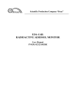
OUTLINE DRAWING
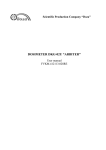
Monoblock Beta-4
Figure A.1 - Overall and fitting dimensions (basic modification)
FVKM.412113.042RE
13
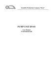
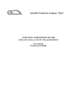
Monoblock Gamma-1-1
Figure A.2 - Overall and fitting dimensions (basic modification 01)
FVKM.412113.042RE
14
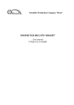
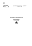
Monoblock Beta-4
Monoblock Gamma-2-1
Monoblock Beta-4
Figure A.3 - Overall and fitting dimensions (basic modification 02)
FVKM.412113.042RE
15
Appendix B
(Obligatory)
OUTPUT CONNECTOR PIN ASSIGNMENT
X1
←
RS-485
USB
Circuit
Data+
Data+12V
Reserved
Reserved
GND
Data+
DataVBUS
GND
Pin
1
2
3
4
5
6
7
8
9
10
FVKM.412113.042RE
16
FVKM.412113.042RE
17
Figure C.1 – Wiring diagram for basic modification
WIRING DIAGRAM
Appendix C
(Reference)
FVKM.412113.042RE
18
Figure C.2 – Wiring diagram for modification 01
FVKM.412113.042RE
19
Figure C.3 – Wiring diagram for basic modification 02
Appendix D
(Obligatory)
LOCATION OF THE EFFECTIVE CENTER OF MEASUREMENT CHANNEL
Effective center
of the first measurement
channel
Figure D.1 – Location of the effective center of the first measurement channel
(dosimeters of basic modification)
FVKM.412113.042RE
20
Effective center
of the first measurement
channel
Effective center of the
second measurement
channel
Figure D.2 – Location of the effective center of the first measurement channel
(modification 01 of dosimeter)
FVKM.412113.042RE
21
Effective center of the first
measurement channel
Effective center of the
second measurement
channel
Figure D.3 – Location of the effective center of the first measurement channel
(modification 02 of dosimeter)
FVKM.412113.042RE
22
Appendix E
(Obligatory)
"DWPTest" SOFTWARE MANUAL
Cont ent
E.1 Purpose of the software …………………………….…..…………
E.2 Requirements for running the software ………………….…..……
E.2.1 System requirements ………………………………………..
E.2.2 Connecting dosimeters to PC ……………………………….
E.3 Input and output data …………………..……….…………………
E.4 Running the software ………………………………………..…….
E.4.1 Software structure, installation and start ……………………
E.4.2 Using the software ……………………….….…………...…
E.5 Protection of the software …………………………………………
23
23
23
23
24
24
24
24
27
This User Manual describes the purpose and features of the software "DWPTest"
(FVKM.004001) for using with dosimeters, as well as how to use the software.
E.1 PURPOSE OF THE SOFTWARE
The software is intended for using with dosimeters that use asynchronous serial communication
channel and corporate data exchange protocol for instrumental networks DiBUS of SPC "Doza".
The software allows doing the following:
- send requests to connected dosimeters and receive responses in automatic mode;
- enter user defined settings and save them during the process of calibration or adjustment of
dosimeters.
The software is used for servicing only; it is not involved in the measurement process and does
not affect metrological characteristics of dosimeters.
Russian or English can be chosen as the interface language of the software.
E.2 REQUIREMENTS FOR RUNNING THE SOFTWARE
E.2.1 System requirements
Minimum requirements for hardware and software:
- operating system Windows ME/2000/XP;
- processor Pentium with clock frequency 120 MHz;
- RAM 64 Mb;
- free space on hard drive at least 60 Mb;
- monitor 15", 800×600 pixels;
- mouse;
- serial port.
E.2.2 Connecting dosimeters to PC
For communication with dosimeters RS-485 or USB interface can be used; USB or RS-485
is chosen automatically after power on.
E.3 INPUT AND OUTPUT DATA
The input data for the software is measurement and other information sent by dosimeter in
reply to the software request.
FVKM.412113.042RE
23
The output data of the software are values of measurement, adjustment and other parameters
sent by authorized user to dosimeter.
The software does not store the measured values of ADER of gamma radiation. Settings for
working with dosimeter are stored in the file "dwpt.ini".
E.4 RUNNING THE SOFTWARE
E.4.1 Software structure, installation and start
The software contains the following files:
- DWPtest.exe – executable file;
- dbg-s11d common.rst – instrument description file for dosimeter for use in operating mode;
- dbg-s11d calibrator.rst – instrument description file for use in setting, calibration and
adjustment modes (file similar to dbg-s11d common.rst, for authorized users only);
- package of instrument description files for reading / writing data of fixed set of parameters of
memory registers of dosimeters (it used in conjunction with dbg-s11d calibrator.rst).
When the software is launched for the first time, it creates a file "dwpt.ini" with its settings in
the system folder of Microsoft Windows.
To install the software, simply copy all files provided by the manufacturer in the folder selected
for installation.
The software does not require installation. To run the software, launch DWPtest.exe.
To exit the software, enter "Terminal" menu and click "EXIT". To save the configuration, click
"Save" button in the pop-up window.
E.4.2 Using the software
E.4.2.1 Setting the software
Before you begin, connect the dosimeter to PC as described in section 2.2. Figure E.1 shows
the main window of the software.
Figure E.1 – Main window of the software after launch
FVKM.412113.042RE
24
To perform operations with the dosimeter, select "Registers" tab in the main window as shown
in the Figure E.2.
Figure E.2 – "Registers" tab
"Registers" tab allows the operator to send requests to the connected dosimeter and receive its
answers in automatic mode. This mode is adapted for users who have no special knowledge and skills
for working with the data exchange interfaces.
Before starting to work with the dosimeter, configure the asynchronous communication port by
performing the following in the bottom part of the main window
1) select the asynchronous port number from the drop-down list; the default port is COM1;
2) select the data rate from the drop-down list; the default value is 9600 bps;
3) select the number of stop bits;
4) select the parity mode; by default there is no parity bit;
5) set the parameter "Receive: inter-byte range, ms" - the time interval between received bytes
of the same packet; by default the interval is 1 ms;
6) set the parameter "Send: inter-byte range, ms" - the time interval between received bytes of
the same packet; by default the interval is 0 ms.
The software automatically saves set parameters of the communication port to a file.
E.4.2.2 Working with dosimeter
Working with dosimeter is performed in the window "Registers". The software allows the
operator to work with dosimeter in two modes:
- the first mode (operational) – sending requests to connected dosimeter and receiving replies
in automatic mode; in this mode, the operator cannot enter data from PC;
- the second mode (setting, calibration, adjusting): this mode allows authorized user to enter
in the dosimeter certain data, setup coefficients and constant parameters. To work in this mode, the
user is supplied with the instrument description file "dbg-s11d calibrator.rst", providing the access to
enter necessary information, which also serves as the access key for the authorized user.
FVKM.412113.042RE
25
To download common settings, select connected dosimeter. To do that, click the "SELECT
DOSIMETER" button and in the dialog box, select file "dbg-s11d common.rst", and click "OPEN".
For loading parameters of the dosimeter, the authorized user must copy the key file provided by
manufacturer "dbg-s11d calibrator.rst" in the software folder and then click "OPEN". The window
"Doza WireNetProtocol – Debugger 1.1.87.0021" will open as shown in Figure E.3 and there will be a
fixed set of parameters "Register"; the current values of parameters requested from the connected
dosimeter will be displayed.
To enter a new value for the parameter, double-click in the "New Value" column against the
selected parameter and enter a new value, then click "TRANSMIT" button. The new value will then be
sent to dosimeter and saved.
If after clicking "TRANSMIT" button the received packets in the original and decoded form
(lower left and right parts of the terminal area): software name and version of the firmware are
displayed unchanged, this means that the information was not transferred to the dosimeter.
Figure E.3 – Content of register
In Figure E.4 an example is presented when unauthorized user attempts to write the changed
parameter in the dosimeter memory, in this case in the right side of the terminal area "New value" the
changed version of the software is displayed.
After completion of the authorized user's work the "dbg-s11d calibrator.rst" file is deleted until
the next calibration or adjustment.
When it is necessary to address only one specific dosimeter instead the broadcast polling of
several dosimeter, click the "CHANGE ADRESS" button and enter unique DiBus-address of this
dosimeter in the window; in this case, the software will poll the specific dosimeter in the
communication line.
FVKM.412113.042RE
26
Figure E.4 – Writing the changed parameter in the dosimeter memory
E.5 PROTECTION OF THE SOFTWARE
The software does not perform any computing with received and saved data and is not involved
in the measurement process.
The process of sending and receiving data is accompanied by an integrity check of data packet,
both on the software side and by dosimeters.
Any authorized or unauthorized modification of the software affecting its functionally
important parts makes it impossible to receive or transmit data.
The integrity of the dosimeter's software and preset parameters is confirmed by absence of
change in the preset parameters checked by the operator in the measurement process, as well as
presence of the authorized user access key file.
FVKM.412113.042RE
27
Appendix F
(Obligatory)
DESCRIPTION OF DATA EXCHANGE REGISTERS OF DiBUS PROTOCOL
Table F.1 – Data for writing to / reading from the dosimeter
Index
00h
Description
R/W
Type
Name (code)
Current values:
- ADER of gamma radiation, Sv/h
- uncertainty ADER, %
- control / status byte
- control of limiting values current / voltage
- selected resource of channel 1
- selected resource of channel 2
Byte to control operation mode XB
Conversion factors of channel 1:
- K – conversion factor
- Kt – dead time
- Kf – intrinsic background
- ID – channel ID
Conversion factors of channel 2:
- K – conversion factor
- Kt – dead time
- Kf – intrinsic background
- ID – channel ID
User-defined (7Dh)
- LSingle (0Dh)
- LSingle (0Dh)
- Byte (01h)
- Byte (01h)
- Byte (01h)
- Byte (01h)
R/W Byte (01h)
R/W User-defined (7Dh)
- LSingle (0Dh)
- LSingle (0Dh)
- LSingle (0Dh)
- Byte (01h)
R/W User-defined (7Dh)
- LSingle (0Dh)
- LSingle (0Dh)
- LSingle (0Dh)
- Byte (01h)
08h
Address of dosimeter
R/W DiBUS_address(21h)
09h
Restarting measurement in channels
W
Byte (01h)
0Ah
Software version
R
Word (03h)
01h
02h
03h
FVKM.412113.042RE
28
R